CN211127589U - Single-stage high-frequency isolated bidirectional direct-current converter and grid-connected energy storage system - Google Patents
Single-stage high-frequency isolated bidirectional direct-current converter and grid-connected energy storage systemDownload PDFInfo
- Publication number
- CN211127589U CN211127589UCN201922190840.XUCN201922190840UCN211127589UCN 211127589 UCN211127589 UCN 211127589UCN 201922190840 UCN201922190840 UCN 201922190840UCN 211127589 UCN211127589 UCN 211127589U
- Authority
- CN
- China
- Prior art keywords
- module
- energy storage
- boost
- input
- resonance
- Prior art date
- Legal status (The legal status is an assumption and is not a legal conclusion. Google has not performed a legal analysis and makes no representation as to the accuracy of the status listed.)
- Withdrawn - After Issue
Links
- 238000004146energy storageMethods0.000titleclaimsabstractdescription66
- 230000002457bidirectional effectEffects0.000titleclaimsabstractdescription61
- 238000006243chemical reactionMethods0.000claimsdescription35
- 238000010521absorption reactionMethods0.000claimsdescription33
- 239000003990capacitorSubstances0.000claimsdescription23
- 230000009466transformationEffects0.000abstractdescription25
- 238000010586diagramMethods0.000description28
- 238000002955isolationMethods0.000description25
- 230000001360synchronised effectEffects0.000description6
- 238000012937correctionMethods0.000description5
- 238000012546transferMethods0.000description4
- 238000001514detection methodMethods0.000description3
- 238000007599dischargingMethods0.000description3
- 238000000034methodMethods0.000description3
- 230000008901benefitEffects0.000description2
- 230000000295complement effectEffects0.000description2
- 238000011217control strategyMethods0.000description2
- 230000005669field effectEffects0.000description2
- 230000006872improvementEffects0.000description2
- 238000012986modificationMethods0.000description2
- 230000004048modificationEffects0.000description2
- 238000011160researchMethods0.000description2
- 230000007547defectEffects0.000description1
- 230000007613environmental effectEffects0.000description1
- 239000000463materialSubstances0.000description1
- 229910044991metal oxideInorganic materials0.000description1
- 150000004706metal oxidesChemical class0.000description1
- 230000010363phase shiftEffects0.000description1
- 238000005070samplingMethods0.000description1
- 229920006395saturated elastomerPolymers0.000description1
- 239000004065semiconductorSubstances0.000description1
- 238000006467substitution reactionMethods0.000description1
Images


Landscapes
- Dc-Dc Converters (AREA)
Abstract
Translated fromChinese
Description
Translated fromChinese技术领域technical field
本实用新型涉及电源模块领域,更具体地说,涉及一种单级式高频隔离型双向直流变换器和包括所述单级式高频隔离型双向直流变换器的并网储能系统。The utility model relates to the field of power modules, in particular to a single-stage high-frequency isolation bidirectional DC converter and a grid-connected energy storage system including the single-stage high-frequency isolation bidirectional DC converter.
背景技术Background technique
随着能源危机的日益加剧和人们环保意识的提高,绿色高效利用能源成为各国研究应用的重点,而高频隔离型宽范围直流变换器的研究更是重中之重。目前,在工程应用中,单级式高频隔离型双向直流变换器通常输入电压范围过窄,无法满足宽输入电压范围。而宽输入电压范围的双向高频隔离型直流变换器大多采用两级式拓扑结构。例如BUCKBOOST+LLC电路级联,通过BUCKBOOST电路提高输入电压范围,通过LLC电路的变压器实现高频隔离。又或者BUCKBOOST+移相全桥电路级联,同样通过BUCKBOOST电路提高输入电压范围,通过移相全桥电路的变压器实现高频隔离。但是不管是BUCKBOOST+LLC电路级联还是BUCKBOOST+移相全桥电路级联相对于单级式拓扑结构而言都增加了开关器件的成本,降低了能量的转换效率。With the increasing energy crisis and the improvement of people's awareness of environmental protection, green and efficient use of energy has become the focus of research and application in various countries, and the research on high-frequency isolated wide-range DC converters is even more important. At present, in engineering applications, the input voltage range of the single-stage high-frequency isolated bidirectional DC converter is usually too narrow to meet the wide input voltage range. However, most of the bidirectional high-frequency isolated DC converters with wide input voltage range adopt a two-stage topology. For example, the BUCKBOOST+LLC circuit is cascaded, the input voltage range is increased through the BUCKBOOST circuit, and the high-frequency isolation is achieved through the transformer of the LLC circuit. Or BUCKBOOST + phase-shifting full-bridge circuits are cascaded, and the input voltage range is also increased through the BUCKBOOST circuit, and high-frequency isolation is achieved through the transformer of the phase-shifting full-bridge circuit. However, both the cascading of BUCKBOOST+LLC circuits or the cascading of BUCKBOOST+ phase-shifting full-bridge circuits increase the cost of switching devices and reduce the energy conversion efficiency compared to the single-stage topology.
实用新型内容Utility model content
本实用新型要解决的技术问题在于,针对现有技术的上述缺陷,提供一种单级式高频隔离型双向直流变换器和包括所述单级式高频隔离型双向直流变换器的并网储能系统,用于以低成本、高效率方式的单级拓扑结构满足宽输入电压范围。The technical problem to be solved by the present invention is to provide a single-stage high-frequency isolation bidirectional DC converter and a grid connection including the single-stage high-frequency isolation bidirectional DC converter in view of the above-mentioned defects of the prior art Energy storage system for a wide input voltage range in a single-stage topology in a low-cost, high-efficiency manner.
本实用新型解决其技术问题所采用的技术方案是:构造一种单级式高频隔离型双向直流变换器,包括:依次电连接的升压储能模块、输入开关网络、变压器模块、谐振模块、输出开关网络,以及与所述升压储能模块和所述谐振模块控制连接的投切控制模块,所述升压储能模块连接输入电源的正极和负极;所述投切控制模块用于在正向变换时控制所述升压储能模块投入、所述谐振模块投出,在反向变换时控制所述升压储能模块投出、所述谐振模块投入。The technical scheme adopted by the utility model to solve the technical problem is: constructing a single-stage high-frequency isolation bidirectional DC converter, comprising: a boost energy storage module, an input switch network, a transformer module, and a resonance module that are electrically connected in sequence , an output switch network, and a switching control module controlled and connected to the boost energy storage module and the resonance module, the boost energy storage module is connected to the positive and negative electrodes of the input power supply; the switching control module is used for The boost energy storage module is controlled to be put in and the resonance module is put in during forward transformation, and the boost energy storage module is controlled to be put in and the resonance module is put in during reverse transformation.
在本实用新型所述的单级式高频隔离型双向直流变换器中,所述谐振模块包括第一谐振单元和第二谐振单元,所述第一谐振单元连接在所述变压器模块的副边第一端和所述输出开关网络的第一输入端之间,所述第二谐振单元经所述谐振投切控制单元连接在所述变压器模块的副边第一端和副边第二端之间。In the single-stage high-frequency isolation bidirectional DC converter of the present invention, the resonance module includes a first resonance unit and a second resonance unit, and the first resonance unit is connected to the secondary side of the transformer module Between the first end and the first input end of the output switch network, the second resonance unit is connected between the first end of the secondary side and the second end of the secondary side of the transformer module through the resonance switching control unit. between.
在本实用新型所述的单级式高频隔离型双向直流变换器中,所述投切控制模块包括用于在正向变换时控制所述升压储能模块投入、在反向变换时控制所述升压储能模块投出的升压投切控制单元,用于在正向变换时控制所述第一谐振单元和所述第二谐振单元投出、在反向变换时控制所述第一谐振单元和所述第二谐振单元投入的谐振投切控制单元。In the single-stage high-frequency isolated bidirectional DC converter of the present invention, the switching control module includes a control module for controlling the boosting energy storage module to be switched on during forward transformation, and for controlling the switching during reverse transformation. The boost switching control unit cast by the boost energy storage module is used to control the throw of the first resonance unit and the second resonance unit during forward transformation, and control the first resonance unit during reverse transformation. A resonance unit and a resonance switching control unit put into the second resonance unit.
在本实用新型所述的单级式高频隔离型双向直流变换器中,所述第一谐振单元包括第一电感和第一电容,所述第二谐振单元包括第二电感,所述第一电感的第一端连接所述变压器模块的副边第一端、第二端经所述第一电容连接所述输出开关网络的第一输入端;所述第二电感的第一端经所述谐振投切控制单元连接所述变压器模块的副边第一端,所述第二电感的第二端连接所述变压器模块的副边第二端。In the single-stage high-frequency isolated bidirectional DC converter of the present invention, the first resonance unit includes a first inductance and a first capacitor, the second resonance unit includes a second inductance, and the first The first end of the inductor is connected to the first end of the secondary side of the transformer module, and the second end is connected to the first input end of the output switch network through the first capacitor; the first end of the second inductor is connected to the first input end of the output switch network through the first capacitor; The resonance switching control unit is connected to the first end of the secondary side of the transformer module, and the second end of the second inductor is connected to the second end of the secondary side of the transformer module.
在本实用新型所述的单级式高频隔离型双向直流变换器中,所述谐振投切控制单元包括与所述第一电感并联的第一谐振开关和与所述第二电感串联的第二谐振开关。In the single-stage high-frequency isolated bidirectional DC converter of the present invention, the resonant switching control unit includes a first resonant switch connected in parallel with the first inductor and a second resonant switch connected in series with the second inductor. Two resonant switches.
在本实用新型所述的单级式高频隔离型双向直流变换器中,所述升压储能模块包括连接在所述输入电源正极和所述输入开关网络的第一输入端的升压储能电感。In the single-stage high-frequency isolated bidirectional DC converter of the present invention, the boost energy storage module includes a boost energy storage connected to the positive pole of the input power supply and the first input end of the input switch network inductance.
在本实用新型所述的单级式高频隔离型双向直流变换器中,所述升压投切控制单元包括并联在所述升压储能电感两端的升压投切开关。In the single-stage high-frequency isolated bidirectional DC converter of the present invention, the boost switching control unit includes a boost switching switch connected in parallel to both ends of the boost energy storage inductor.
在本实用新型所述的单级式高频隔离型双向直流变换器中,所述升压储能模块进一步包括连接在所述输出电源正极和负极之间的输入滤波电容和连接在所述输入开关网络的第一输入端和第二输入端之间的吸收单元。In the single-stage high-frequency isolated bidirectional DC converter of the present invention, the boost energy storage module further comprises an input filter capacitor connected between the positive pole and the negative pole of the output power supply, and an input filter capacitor connected to the input an absorption unit between the first input terminal and the second input terminal of the switching network.
在本实用新型所述的单级式高频隔离型双向直流变换器中,所述输入开关网络和所述输出开关网络包括全桥开关管网络或半桥开关管网络;所述吸收单元包括吸收二极管、吸收电容和吸收电阻,所述吸收二极管的阳极连接所述输入开关网络的第一输入端、阴极经所述吸收电容连接所述输入开关网络的第二输入端,所述吸收电阻并联在所述吸收二极管或所述吸收电容两端。In the single-stage high-frequency isolated bidirectional DC converter of the present invention, the input switch network and the output switch network include a full-bridge switch network or a half-bridge switch network; the absorption unit includes an absorption diode, absorption capacitor and absorption resistor, the anode of the absorption diode is connected to the first input terminal of the input switch network, and the cathode is connected to the second input terminal of the input switch network through the absorption capacitor, and the absorption resistance is connected in parallel with both ends of the absorption diode or the absorption capacitor.
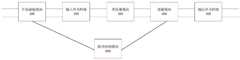
本实用新型解决其技术问题采用的另一技术方案是,构造一种并网储能系统,包括电池模块、光伏组件、DC/DC模块、DC滤波模块、DC/AC模块、AC滤波模块、继电器、负载、电网模块以及所述的单级式高频隔离型双向直流变换器,所述光伏组件经所述DC/DC模块连接到所述DC滤波模块,所述电池模块经所述单级式高频隔离型双向直流变换器连接到所述DC滤波模块,所述DC滤波模块进一步依次经DC/AC模块、AC滤波模块、继电器连接负载或电网模块。Another technical solution adopted by the utility model to solve the technical problem is to construct a grid-connected energy storage system, which includes a battery module, a photovoltaic component, a DC/DC module, a DC filter module, a DC/AC module, an AC filter module, and a relay. , load, power grid module and the single-stage high-frequency isolation bidirectional DC converter, the photovoltaic module is connected to the DC filter module through the DC/DC module, and the battery module is connected to the single-stage type The high-frequency isolated bidirectional DC converter is connected to the DC filter module, and the DC filter module is further connected to a load or a power grid module through a DC/AC module, an AC filter module, and a relay in sequence.
本实用新型的单级式高频隔离型双向直流变换器和并网储能系统,通过采用投切控制模块,在正向变换时投入升压储能模块、投出谐振模块,实现宽输入范围电压向相对稳定的输出电压变换,而在反向变换时,投出升压储能模块、投入谐振模块,从而将相对稳定的输入电压变换为宽输出范围的输出电压,因此可以低成本、高效率方式的单级拓扑结构满足宽输入电压范围。其与纯谐振型LLC变换器相比可以提高输入电压范围,而不需增加额外电路。与传统的移相全桥变换器相比同样可以提高输入电压范围;并可利用LLC拓扑优势,提高直流功率反向变换的效率。The single-stage high-frequency isolated bidirectional DC converter and grid-connected energy storage system of the utility model realizes a wide input range by adopting a switching control module, inputting a boost energy storage module and a resonance module during forward conversion. The voltage is converted to a relatively stable output voltage, and in the reverse conversion, the boost energy storage module and the resonant module are put in, so as to convert the relatively stable input voltage into an output voltage with a wide output range, so it can be low-cost and high-efficiency. The single-stage topology in efficiency mode satisfies a wide input voltage range. Compared with pure resonant LLC converters, it can increase the input voltage range without adding additional circuitry. Compared with the traditional phase-shift full-bridge converter, the input voltage range can also be improved; and the LLC topology advantage can be used to improve the efficiency of DC power reverse conversion.
附图说明Description of drawings
下面将结合附图及实施例对本实用新型作进一步说明,附图中:The utility model will be further described below in conjunction with the accompanying drawings and embodiments, in the accompanying drawings:
图1是本实用新型的单级式高频隔离型双向直流变换器的第一优选实施例的原理框图;Fig. 1 is the principle block diagram of the first preferred embodiment of the single-stage high-frequency isolation bidirectional DC converter of the present invention;
图2是本实用新型的单级式高频隔离型双向直流变换器的第二优选实施例的原理框图;Fig. 2 is the principle block diagram of the second preferred embodiment of the single-stage high-frequency isolation bidirectional DC converter of the present invention;
图3是本实用新型的单级式高频隔离型双向直流变换器的第三优选实施例的电路图;3 is a circuit diagram of a third preferred embodiment of the single-stage high-frequency isolation bidirectional DC converter of the present invention;
图4A-4C示出了图3所示的单级式高频隔离型双向直流变换器的正向变换时充电能量、正负能量传递示意图;4A-4C show schematic diagrams of charging energy and positive and negative energy transfer during forward conversion of the single-stage high-frequency isolated bidirectional DC converter shown in FIG. 3;
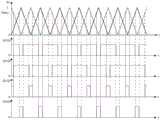
图5是图3所示的单级式高频隔离型双向直流变换器的直流正向变换的开关管驱动发波示意图;FIG. 5 is a schematic diagram of the switching tube driving wave of the DC forward conversion of the single-stage high-frequency isolation bidirectional DC converter shown in FIG. 3;
图6是图3所示的单级式高频隔离型双向直流变换器的直流正向变换的控制框图;FIG. 6 is a control block diagram of the DC forward conversion of the single-stage high-frequency isolated bidirectional DC converter shown in FIG. 3;
图7A-7B示出了图3所示的单级式高频隔离型双向直流变换器的反向变换时正负能量传递示意图;7A-7B show schematic diagrams of positive and negative energy transfer during reverse conversion of the single-stage high-frequency isolated bidirectional DC converter shown in FIG. 3;
图8是图3所示的单级式高频隔离型双向直流变换器的直流反变换的开关管驱动发波示意图;FIG. 8 is a schematic diagram of the switching tube driving wave generation of the DC inverse conversion of the single-stage high-frequency isolated bidirectional DC converter shown in FIG. 3;
图9是图3所示的单级式高频隔离型双向直流变换器的直流反向变换的控制框图;FIG. 9 is a control block diagram of the DC reverse conversion of the single-stage high-frequency isolated bidirectional DC converter shown in FIG. 3;
图10A-10B示出了本实用新型的单级式高频隔离型双向直流变换器应用电路原理图;10A-10B show the application circuit schematic diagram of the single-stage high-frequency isolated bidirectional DC converter of the present invention;
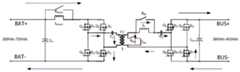
图11是本实用新型的单级式高频隔离型双向直流变换器的第四优选实施例的电路图;11 is a circuit diagram of the fourth preferred embodiment of the single-stage high-frequency isolation bidirectional DC converter of the present invention;
图12是本实用新型的并网储能系统的第一优选实施例的原理框图;12 is a schematic block diagram of the first preferred embodiment of the grid-connected energy storage system of the present invention;
图13A-13C示出了DA/AC模块的单相可选实现方式;Figures 13A-13C illustrate a single-phase alternative implementation of a DA/AC module;
图14A-14C示出了DA/AC模块的三相可选实现方式。14A-14C illustrate a three-phase alternative implementation of a DA/AC module.
具体实施方式Detailed ways
为了使本实用新型的目的、技术方案及优点更加清楚明白,以下结合附图及实施例,对本实用新型进行进一步详细说明。应当理解,此处所描述的具体实施例仅仅用以解释本实用新型,并不用于限定本实用新型。In order to make the purpose, technical solutions and advantages of the present utility model more clearly understood, the present utility model will be further described in detail below with reference to the accompanying drawings and embodiments. It should be understood that the specific embodiments described herein are only used to explain the present invention, and are not intended to limit the present invention.
本实用新型涉及一种单级式高频隔离型双向直流变换器,包括:依次电连接的升压储能模块、输入开关网络、变压器模块、谐振模块、输出开关网络,以及与所述升压储能模块和所述谐振模块控制连接的投切控制模块,所述升压储能模块连接输入电源的正极和负极;所述投切控制模块用于在正向变换时控制所述升压储能模块投入、所述谐振模块投出,在反向变换时控制所述升压储能模块投出、所述谐振模块投入。本实用新型通过采用投切控制模块,在正向变换时投入升压储能模块、投出谐振模块,实现宽输入范围电压向相对稳定的输出电压变换,而在反向变换时,投出升压储能模块、投入谐振模块,从而将相对稳定的输入电压变换为宽输出范围的输出电压,因此可以低成本、高效率方式的单级拓扑结构满足宽输入电压范围。The utility model relates to a single-stage high-frequency isolated bidirectional DC converter, comprising: a boosting energy storage module, an input switch network, a transformer module, a resonance module, and an output switch network electrically connected in sequence; The energy storage module and the resonant module are controlled and connected to the switching control module, the boost energy storage module is connected to the positive pole and the negative pole of the input power supply; the switching control module is used to control the boost energy storage during forward transformation. The energy module is put in, the resonance module is put in, and the boost energy storage module is controlled to be put in and the resonance module is put in during reverse transformation. By adopting the switching control module, the utility model puts in the boosting energy storage module and throws out the resonance module during the forward transformation, so as to realize the transformation from the wide input range voltage to the relatively stable output voltage; It can convert the relatively stable input voltage into an output voltage with a wide output range, so it can meet the wide input voltage range with a low-cost, high-efficiency single-stage topology.
双向直流变换系统,对电压变换范围、功率密度、成本、体积、效率的要求是必不可少的。然而,由于传统的拓扑结构通常采用两级式结构,通过额外增加一级升降压电路来提高输入电压范围。因此,传统两级式拓扑结构因开关器件的增加,不可避免的引出成本增加、功率密度减小、转换效率降低、控制难度增高等一系列问题。现有产品大多都是通过采用多个电路的串并联,组合成较大容量和较宽范围的双向直流变换器。然而,本申请的实用新型人创造性的想到将BOOST升压模块与高频隔离型直流变换模块相结合起来,通过BOOST升压模块与高频变压器组合达到升降压的目的;双向直流反向变换采用传统的LLC谐振电路减小开关损耗,提高系统效率,这一举措突破了本领域中一向以来的惯有思维模式。The bidirectional DC conversion system is indispensable to the requirements of voltage conversion range, power density, cost, volume and efficiency. However, since the traditional topology usually adopts a two-stage structure, the input voltage range is increased by adding an additional stage of buck-boost circuit. Therefore, due to the increase of switching devices, the traditional two-stage topology inevitably leads to a series of problems such as increase in cost, decrease in power density, decrease in conversion efficiency, and increase in control difficulty. Most of the existing products are combined into bidirectional DC converters with larger capacity and wider range by using multiple circuits in series and parallel. However, the inventor of the present application creatively thought of combining a BOOST booster module with a high-frequency isolated DC conversion module, so as to achieve the purpose of boosting and boosting through the combination of the BOOST booster module and a high-frequency transformer; bidirectional DC reverse conversion The traditional LLC resonant circuit is used to reduce the switching loss and improve the system efficiency, which breaks through the conventional thinking mode in this field.
图1是本实用新型的单级式高频隔离型双向直流变换器的第一优选实施例的原理框图。如图1所示,本实用新型的单级式高频隔离型双向直流变换器,包括:依次电连接的升压储能模块100、输入开关网络200、变压器模块300、谐振模块400、输出开关网络500,以及与所述升压储能模块100和所述谐振模块400控制连接的投切控制模块600,所述升压储能模块100连接输入电源的正极和负极。所述投切控制模块600用于在正向变换时控制所述升压储能模块100投入、所述谐振模块400投出,在反向变换时控制所述升压储能模块100投出、所述谐振模块400投入。FIG. 1 is a schematic block diagram of the first preferred embodiment of the single-stage high-frequency isolated bidirectional DC converter of the present invention. As shown in FIG. 1 , the single-stage high-frequency isolated bidirectional DC converter of the present invention includes: a boost energy storage module 100, an input switch network 200, a
在本实用新型的优选实施例中,所述升压储能模块100可以采用任何已知的电容和电感构建。所述变压器模块300可以包括一个或者多个串联的变压器。所述输入开关网络200和输出开关网络500可以包括任何已知的全桥开关管网络或半桥开关管网络。所述谐振模块400可以是任何LLC谐振模块,CLLC谐振模块,LC谐振模块等等。所述投切控制模块600可以是任何硬件开关或电路,例如空气开关、功率开关管、继电器或接触器,也可以是任何软开关模块,或者器件。In a preferred embodiment of the present invention, the boost energy storage module 100 can be constructed using any known capacitance and inductance. The
本实用新型通过采用投切控制模块,在正向变换时投入升压储能模块、投出谐振模块,实现宽输入范围电压向相对稳定的输出电压变换,而在反向变换时,投出升压储能模块、投入谐振模块,从而将相对稳定的输入电压变换为宽输出范围的输出电压,因此可以低成本、高效率方式的单级拓扑结构满足宽输入电压范围。By adopting the switching control module, the utility model puts in the boosting energy storage module and throws out the resonance module during the forward transformation, so as to realize the transformation from the wide input range voltage to the relatively stable output voltage; It can convert the relatively stable input voltage into an output voltage with a wide output range, so it can meet the wide input voltage range with a low-cost, high-efficiency single-stage topology.
图2是本实用新型的单级式高频隔离型双向直流变换器的第二优选实施例的原理框图。在图2所示实施例中,本实用新型的单级式高频隔离型双向直流变换器,包括:依次电连接的升压储能模块100、输入开关网络200、变压器模块300、谐振模块400、输出开关网络500,以及与所述升压储能模块100和所述谐振模块400控制连接的投切控制模块600,所述升压储能模块100连接输入电源的正极和负极。进一步的所述谐振模块400包括第一谐振单元410和第二谐振单元420。FIG. 2 is a schematic block diagram of the second preferred embodiment of the single-stage high-frequency isolation bidirectional DC converter of the present invention. In the embodiment shown in FIG. 2 , the single-stage high-frequency isolated bidirectional DC converter of the present invention includes: a boost energy storage module 100 , an input switch network 200 , a
所述第一谐振单元410连接在所述变压器模块300的副边第一端和所述输出开关网络500的第一输入端之间,所述第二谐振单元420连接在所述变压器模块300的副边第一端和副边第二端之间。所述投切控制模块600包括用于在正向变换时控制所述升压储能模块100投入、在反向变换时控制所述升压储能模块100投出的升压投切控制单元610,用于在正向变换时控制所述第一谐振单元410和所述第二谐振单元420投出、在反向变换时控制所述第一谐振单元410和所述第二谐振单元420投入的谐振投切控制单元620。The first resonance unit 410 is connected between the first terminal of the secondary side of the
在本实用新型的优选实施例中,所述升压储能模块100可以采用任何已知的电容和电感构建。所述变压器模块300可以包括一个或者多个串联的变压器。所述输入开关网络200和输出开关网络500可以包括任何已知的全桥开关管网络或半桥开关管网络。第一谐振单元410和第二谐振单元420以是任何LC谐振模块。所述升压投切控制单元610和谐振投切控制单元620可以是任何硬件开关或电路,例如空气开关、功率开关管、继电器或接触器,也可以是任何软开关模块,或者器件。In a preferred embodiment of the present invention, the boost energy storage module 100 can be constructed using any known capacitance and inductance. The
本实用新型通过采用投切控制模块,在正向变换时投入升压储能模块、投出谐振模块,实现宽输入范围电压向相对稳定的输出电压变换,而在反向变换时,投出升压储能模块、投入谐振模块,从而将相对稳定的输入电压变换为宽输出范围的输出电压,因此可以低成本、高效率方式的单级拓扑结构满足宽输入电压范围。By adopting the switching control module, the utility model puts in the boosting energy storage module and throws out the resonance module during the forward transformation, so as to realize the transformation from the wide input range voltage to the relatively stable output voltage; It can convert the relatively stable input voltage into an output voltage with a wide output range, so it can meet the wide input voltage range with a low-cost, high-efficiency single-stage topology.
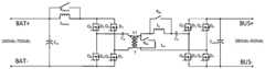
图3是本实用新型的单级式高频隔离型双向直流变换器的第三优选实施例的电路图。如图3所示,本实用新型的单级式高频隔离型双向直流变换器,包括:依次电连接的升压储能模块100、输入开关网络200、变压器模块300、谐振模块400、输出开关网络500,以及与所述升压储能模块100和所述谐振模块400控制连接的投切控制模块600,所述升压储能模块100连接输入电源的正极和负极。进一步的所述谐振模块400包括第一谐振单元410和第二谐振单元420。所述投切控制模块600包括升压投切控制单元610和谐振投切控制单元620。3 is a circuit diagram of a third preferred embodiment of the single-stage high-frequency isolation bidirectional DC converter of the present invention. As shown in FIG. 3 , the single-stage high-frequency isolated bidirectional DC converter of the present invention includes: a boost energy storage module 100 , an input switch network 200 , a
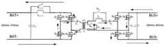
在图3所示的优选实施例中,所述升压储能模块100包括连接在输入电源正极BAT+和负极BAT-之间的输入滤波电容Cin和连接在所述输入电源正极BAT+和所述输入开关网络200的第一输入端的升压储能电感Lboost。所述输入开关网络200包括开关管Q1-Q4以及反向并联二极管D1-D4构成的全桥开关管网络。所述第一谐振单元410包括第一电感Lr和第一电容C1,所述第二谐振单元420包括第二电感Lm。所述第一电感Lr的第一端连接所述变压器模块300的副边第一端。第二端经所述第一电容C1连接所述输出开关网络500的第一输入端。所述第二电感Lm的第一端经所述谐振投切控制单元620连接所述变压器模块300的副边第一端,所述第二电感Lm的第二端连接所述变压器模块300的副边第二端。所述输出开关网络500包括开关管Q5-Q8以及反向并联二极管D5-D8构成的全桥开关管网络。进一步地所述输出开关网络500还可以包括输出滤波电容Cout。所述输出滤波电容Cout的两端连接正负母线。In the preferred embodiment shown in FIG. 3 , the boost energy storage module 100 includes an input filter capacitor C in connected between the positive electrode BAT+ and the negative electrode BAT- of the input power supply, and an input filter capacitor Cin connected between the positive electrode BAT+ of the input power supply and the negative electrode BAT- The boost energy storage inductor Lboost of the first input terminal of the input switch network 200 is input. The input switch network 200 includes a full-bridge switch network composed of switch transistors Q1 -Q4 and anti-parallel diodes D1 -D4 . The first resonance unit 410 includes a first inductor Lr and a first capacitor C1 , and the second resonance unit 420 includes a second inductor Lm . The first end of the first inductor Lr is connected to the first end of the secondary side of the
在本实施例中,所述谐振投切控制单元包括与所述第一电感Lr并联的第一谐振开关Kllc和与所述第二电感Lm串联的第二谐振开关Km。所述升压投切控制单元包括并联在所述升压储能电感Lboost两端的升压投切开关Kboost。在本优选实施例中,第一谐振开关Kllc、第二谐振开关Km和升压投切开关Kboost都采用空气开关。在本实用新型的优选实施例中所述开关管可以是金属-氧化物半导体场效应晶体管、绝缘栅双极晶体管、电力晶体管、绝缘栅场效应管、门极可关断晶闸管或晶闸管。所述升压储能模块100的输入端可以连接电池模块或负载模块、单相无源功率因数校正电路、单相有源功率因数校正电路、三相无源功率因数校正电路、三相有源功率因数校正电路。In this embodiment, the resonant switching control unit includes a first resonant switch Kllc connected in parallel with the first inductor Lr and a second resonant switch Km connected in series with the second inductor L m. The boost switching control unit includes a boost switching switch Kboost connected in parallel to both ends of the boost energy storage inductor L boost. In this preferred embodiment, the first resonant switch Kllc , the second resonant switch Km and the boost switching switch Kboost all use air switches. In a preferred embodiment of the present invention, the switch can be a metal-oxide semiconductor field effect transistor, an insulated gate bipolar transistor, a power transistor, an insulated gate field effect transistor, a gate turn-off thyristor or a thyristor. The input end of the boost energy storage module 100 can be connected to a battery module or a load module, a single-phase passive power factor correction circuit, a single-phase active power factor correction circuit, a three-phase passive power factor correction circuit, and a three-phase active power factor correction circuit. Power factor correction circuit.
在本实用新型的进一步的优选实施例中,所述升压储能模块进一步包括连接在所述输入开关网络的第一输入端和第二输入端之间的吸收单元。在图11所示的实施例中,所述吸收单元包括吸收二极管Df、吸收电容Cf和吸收电阻Rf。所述吸收二极管Df的阳极连接所述输入开关网络200的第一输入端、阴极经所述吸收电容Cf连接所述输入开关网络200的第二输入端,所述吸收电阻Rf并联在所述吸收电容Cf两端。当然,所述吸收电阻Rf还可以连接在所述吸收二极管Df两端。在本实用新型的其他优选实施例中,所述吸收单元还可以采用其他构造,或者包括其他元件。In a further preferred embodiment of the present invention, the boost energy storage module further includes an absorption unit connected between the first input end and the second input end of the input switch network. In the embodiment shown in FIG. 11 , the absorption unit includes a absorption diode Df , a absorption capacitor Cf and a absorption resistance Rf . The anode of the absorption diode Df is connected to the first input terminal of the input switch network 200 , the cathode is connected to the second input terminal of the input switch network 200 through the absorption capacitor Cf , and the absorption resistance Rf is connected in parallel with the input switch network 200 . the two ends of the absorption capacitor Cf . Of course, the absorption resistor Rf may also be connected to both ends of the absorption diode Df . In other preferred embodiments of the present invention, the absorption unit may also adopt other structures or include other elements.
图4A-4C和图7A-7B分别示出了其正向变换时充电能量、正负能量传递示意图和反向变换时正负能量传递示意图。图5和8分别示出了其直流正向和反向变换的开关管驱动发波示意图。图6和9分别示出了其直流正向变换和直流反向变换的控制框图。图10A-10B示出了应用电路示意图。下面结合图3-10B对本实用新型的原理说明如下。Figures 4A-4C and Figures 7A-7B respectively show a schematic diagram of charging energy, positive and negative energy transfer during forward transformation, and a schematic diagram of positive and negative energy transfer during reverse transformation. Figures 5 and 8 respectively show the schematic diagrams of the switching tube driving and generating waves of its DC forward and reverse conversion. Figures 6 and 9 show the control block diagrams of its DC forward conversion and DC reverse conversion, respectively. 10A-10B show schematic diagrams of application circuits. The principle of the present utility model is described below with reference to FIGS. 3-10B .
在正向变换阶段:In the forward transformation stage:
在步骤一中,断开空气开关Kboost、断开空气开关Klm、闭合空气开关Kllc,将BOOST升压与变压器模块相结合,实现输入电源侧向输出侧的升降压。In
在步骤二中,变压器模块的高压侧全桥电路开关管按以下方式控制:开关管Q1、开关管Q3驱动相同,开关管Q2、开关管Q4驱动相同,开关管Q1、开关管Q2驱动占空比相同、相位交错180度;In
在步骤三中,当变压器模块的高压侧开关管Q1、开关管Q2、开关管Q3、开关管Q4全部导通时,输入电源向电感Lboost充电;此时变压器模块的低压侧开关管Q5、开关管Q6、开关管Q7、开关管Q8均关断,具体电路示意如图4A所示。In step 3, when the high-voltage side switch tube Q1 , switch tube Q2 , switch tube Q3 , and switch tube Q4 of the transformer module are all turned on, the input power is charged to the inductor Lboost ; at this time, the low-voltage side of the transformer module The switch tube Q5 , the switch tube Q6 , the switch tube Q7 , and the switch tube Q8 are all turned off, and a specific circuit diagram is shown in FIG. 4A .
在步骤四中,当变压器模块的高压侧开关管Q1、开关管Q3导通,开关管Q2、开关管Q4关断时,输入电源与电感Lboost均放电;此时变压器模块的低压侧开关管Q5、开关管Q7导通,开关管Q6、开关管Q8关断,进行同步整流;具体电路示意如图4B所示。In step 4, when the high-voltage side switch tube Q1 and the switch tube Q3 of the transformer module are turned on, and the switch tube Q2 and the switch tube Q4 are turned off, both the input power supply and the inductor Lboost are discharged; The low-voltage side switch tube Q5 and the switch tube Q7 are turned on, and the switch tube Q6 and the switch tube Q8 are turned off to perform synchronous rectification; a schematic diagram of the specific circuit is shown in FIG. 4B .
在步骤五中,当变压器模块的高压侧开关管Q1、开关管Q3关断,开关管Q2、开关管Q4导通时,电源与电感Lboost均放电;此时变压器模块的低压侧开关管Q5、开关管Q7关断,开关管Q6、开关管Q8导通,进行同步整流;具体电路示意如图4C所示。In step 5, when the high-voltage side switch tubes Q1 and Q3 of the transformer module are turned off, and the switch tubes Q2 and Q4 are turned on, both the power supply and the inductor Lboost are discharged; at this time, the low voltage of the transformer module is The side switch tubeQ5 and the switch tubeQ7 are turned off, and the switch tubeQ6 and the switch tubeQ8 are turned on to perform synchronous rectification; a schematic diagram of the specific circuit is shown in Figure 4C.
正向变换控制目标是稳定输出侧电压(即母线电压)、限制功率、改善电流纹波,因此采用电压电流双闭环控制:由BUS电压PI环路计算电流参考值,再经过电流PI环路计算BOOST升压占空比,再加前馈量计算实际控制开关管占空比;具体发波控制方式如图5所示、控制框图如图6所示。The goal of forward conversion control is to stabilize the output side voltage (that is, the bus voltage), limit the power, and improve the current ripple. Therefore, the voltage and current double closed-loop control is adopted: the current reference value is calculated by the BUS voltage PI loop, and then calculated by the current PI loop. The boost duty cycle of BOOST, plus the feedforward amount to calculate the actual control switch tube duty cycle; the specific wave control method is shown in Figure 5, and the control block diagram is shown in Figure 6.
在反向变换阶段:In the inverse transformation stage:
在步骤一中,闭合空气开关Kboost,闭合空气开关Klm,断开空气开关Kllc,将LLC谐振模块与变压器模块相结合,实现输出侧向电源侧的升降压;开关管Q1、开关管Q2、开关管Q3、开关管Q4、开关管Q5、开关管Q6、开关管Q7、开关管Q8均以恒定占空比进行控制,通过调整开关频率(调频),实现对反向输出电压的控制。In
在步骤二中,变压器模块的低压侧全桥电路开关管按以下方式控制:开关管Q5、开关管Q7驱动相同,开关管Q6、开关管Q8驱动相同,开关管Q5、开关管Q8驱动互补,并通过调节死区时间,实现对占空比的控制。In
在步骤三中,当变压器模块的低压侧开关管Q5、开关管Q7导通,开关管Q6、开关管Q8关断时,输出侧通过变压器模块向电源侧传递能量;此时变压器模块的高压侧开关管Q1、开关管Q3导通,开关管Q2、开关管Q4关断,进行同步整流;具体电路示意如图7A所示。In step 3, when the low-voltage side switch tubes Q5 and Q7 of the transformer module are turned on, and the switch tubes Q6 and Q8 are turned off, the output side transmits energy to the power supply side through the transformer module; at this time, the transformer The high-voltage side switch tubes Q1 and Q3 of the module are turned on, and the switch tubes Q2 and Q4 are turned off to perform synchronous rectification; the schematic diagram of the specific circuit is shown in FIG. 7A .
在步骤四中,当变压器模块的低压侧开关管Q5、开关管Q7关断,开关管Q6、开关管Q8导通时,输出侧通过变压器模块向电源侧传递能量;此时变压器模块的高压侧开关管Q1、开关管Q3关断,开关管Q2、开关管Q4导通,进行同步整流;具体电路示意如图7B所示。In step 4, when the low-voltage side switch tubes Q5 and Q7 of the transformer module are turned off, and the switch tubes Q6 and Q8 are turned on, the output side transmits energy to the power supply side through the transformer module; at this time, the transformer The high-voltage side switch tube Q1 and the switch tube Q3 of the module are turned off, and the switch tube Q2 and the switch tube Q4 are turned on to perform synchronous rectification; a schematic diagram of the specific circuit is shown in FIG. 7B .
反向变换控制目标是稳定电源电压,同时限制功率,采用电压电流双闭环控制:由电源电压PI环路计算电流参考值,再经过电流PI环路计算LLC频率调整量,最后加上前馈量计算实际控制开关的频率;具体发波控制方式如图8所示、控制框图如图9所示。在恒流控制阶段,电源电压PI环饱和;在恒压控制阶段与浮充阶段,电源电压PI环将退饱和。The goal of the reverse conversion control is to stabilize the power supply voltage and limit the power at the same time. The voltage and current double closed-loop control is adopted: the current reference value is calculated by the power supply voltage PI loop, and then the LLC frequency adjustment is calculated through the current PI loop, and finally the feedforward is added. Calculate the frequency of the actual control switch; the specific wave control method is shown in Figure 8, and the control block diagram is shown in Figure 9. In the constant current control stage, the power supply voltage PI loop is saturated; in the constant voltage control stage and the floating charge stage, the power supply voltage PI loop will desaturate.
本实用新型提出的单级式高频隔离型双向直流变换器,创新的将BOOST升压电路与高频隔离LLC谐振模块相结合实现对高频变压器高压侧进行升压的功能,再通过高频变压器变比降压,其低压侧可使用低耐压开关器件,节约成本;在有效扩宽输入电压范围的前提下,未增加开关器件,可降低系统体积、简化控制;本实用新型通过单级功率变换电路,实现宽输入电压范围的双向直流变换,可提高系统转换效率。电压电流双闭环控制策略,控制简单,便于推广应用;采用紧凑的单级功率变换、效率更高,成本更低。The single-stage high-frequency isolation bidirectional DC converter proposed by the utility model innovatively combines the BOOST boosting circuit with the high-frequency isolation LLC resonant module to realize the function of boosting the high-voltage side of the high-frequency transformer, and then passes the high-frequency The transformer ratio is stepped down, and the low-voltage side can use low-voltage switching devices, which saves costs; on the premise of effectively expanding the input voltage range, no switching devices are added, which can reduce the system volume and simplify control; the utility model adopts a single-stage The power conversion circuit realizes bidirectional DC conversion with a wide input voltage range, which can improve the conversion efficiency of the system. Voltage and current double closed-loop control strategy, simple control, easy to popularize and apply; compact single-stage power conversion, higher efficiency and lower cost.
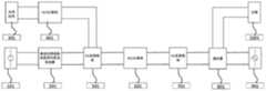
图12是本实用新型的并网储能系统的第一优选实施例的原理框图。如图12所示,该并网储能系统,包括电池模块101、光伏组件301、DC/DC模块401、DC滤波模块501、DC/AC模块601、AC滤波模块701、继电器801、负载1001、电网模块901以及单级式高频隔离型双向直流变换器201。所述光伏组件301经DC/DC模块401连接到所述DC滤波模块501,所述电池模块101经所述单级式高频隔离型双向直流变换器201连接到所述DC滤波模块501,所述DC滤波模块进一步依次经DC/AC模块601、AC滤波模块701、继电器801连接负载10011或电网模块901。FIG. 12 is a schematic block diagram of the first preferred embodiment of the grid-connected energy storage system of the present invention. As shown in FIG. 12, the grid-connected energy storage system includes a
本领域技术人员知悉,电池模块101、光伏组件301、DC/DC模块401、DC滤波模块501、DC/AC模块601、AC滤波模块701、继电器801、负载1001、电网模块901可以采用本领域中已知的任何相关模块。图13A-13C示出了DA/AC模块的单相可选实现方式。图14A-14C示出了DA/AC模块的三相可选实现方式。所述光伏组件301可以是PV光伏组件。所述单级式高频隔离型双向直流变换器201可以参照前述任何实施例构造。Those skilled in the art know that the
在本实用新型的优选实施例中,所述电池模块101回路中串联有电流传感器;所述PV光伏组件301回路中串联有电流传感器;所述电网模块901回路中串联有电流传感器;所述负载1001回路中串联有电流传感器;所述继电器网络801输入输出交流电压分别通过电压传感器进行采样;所述电池模块101、PV光伏组件301、DC滤波模块501两端的直流电压分别通过电阻串并联和线性光耦电路进行采样。In a preferred embodiment of the present invention, a current sensor is connected in series in the circuit of the
下面对本实用新型的并网储能系统的工作原理进行详细描述,具体步骤为:The working principle of the grid-connected energy storage system of the present invention is described in detail below, and the specific steps are:
步骤一、检测电池模块101、PV光伏组件301、电网模块901接入情况。Step 1: Detect the connection status of the
步骤二、若仅电池模块101,其工作于离网运行模式:电池模块101放电,向负载1001供电。Step 2: If there is only the
步骤三、若仅PV光伏组件301,其工作于离网运行模式:PV光伏组件301放电,向负载1001供电。Step 3. If only the PV
步骤四、若仅接入电网模块901,其工作于并网运行模式:电网模块901向负载1001供电。Step 4: If only the
步骤五、若仅接入PV光伏组件301与电网模块901,其工作于并网运行模式与光伏并网逆变器相同:首先,母线软启,主要是控制非隔离型DC/DC模块401将PV光伏组件301的电压变换为理想电压输出;其次,软件锁相,主要是对电网模块901的相位进行软件锁相;再次,继电器检测,主要是对继电器模块801进行检测,闭合继电器,将电网模块901以及负载1001接入系统;最后,最大功率跟踪,主要是对PV光伏组件301进行最大功率点跟踪。Step 5. If only the PV
步骤六、若仅接入PV光伏组件301与电池模块101,其工作于离网运行模式:轻载时,将PV光伏组件301能量输送给电池模块101以及负载1001,电池模块101处于充电模式;重载时,将PV光伏组件301与电池模块101能量输送给负载1001,电池模块101处于放电模式。Step 6. If only the PV
步骤七、若仅接入电池模块101与电网模块901,其工作于并网运行模式与光伏并网逆变器类似:首先,母线软启,主要是控制单级式高频隔离型双向直流变换器201将电池模块101的电压变换为理想电压输出;其次,软件锁相,主要是对电网模块901的相位进行软件锁相;再次,继电器检测,主要是对继电器模块801进行检测,闭合继电器,将电网模块901以及负载1001接入系统;最后,电池模块101功率流向控制,主要是判断电池模块101是充电模式还是放电模式。Step 7. If only the
步骤八、若接入电池模块101、PV光伏组件301与电网模块901,其工作于并网运行模式与光伏并网逆变器类似:首先,母线软启,主要是控制单级式高频隔离型双向直流变换器201将电池模块101的电压变换为理想电压输出或控制非隔离型DC/DC模块401将PV光伏组件301的电压变换为理想电压输出;其次,软件锁相,主要是对电网模块901的相位进行软件锁相;再次,继电器检测,主要是对继电器网络801进行检测,闭合继电器,将电网模块901以及负载1001接入系统;最后,最大功率跟踪,主要是对PV光伏组件301进行最大功率点跟踪,同时判断电池模块101功率流向即电池模块101是充电模式还是放电模式。Step 8. If the
进一步分析单级式高频隔离型双向直流变换器201的充电放电原理Further analysis of the charging and discharging principle of the single-stage high-frequency isolated
放电运行模式:Discharge operation mode:
在步骤一中,断开空气开关Kboost、断开空气开关Klm、闭合空气开关Kllc,将BOOST升压与变压器模块相结合,实现输入电源侧向输出侧的升降压。通过调整变压器模块的高压侧开关管和变压器模块的低压侧开关管的占空比,实现对电池模块101的放电升降压与高频隔离功能,In
具体为:变压器模块的高压侧开关管占空比软起,直至最大50%,得到初始占空比值,且保证同一桥臂的开关器件驱动占空比相同、相位交错180度,不同桥臂间相对的开关器件驱动相同。给定所需的DC滤波模块501的电压作为放电电压闭环参考值,将DC滤波模块501两端的实际直流电压作为放电电压闭环反馈值,输出放电电流闭环给定值。将电池模块101回路中串联电流传感器所采样的电流值作为放电电流闭环的反馈值,输出变压器模块的高压侧开关管占空比调整量。Specifically, the duty cycle of the high-voltage side switch tube of the transformer module is softened until the maximum 50%, and the initial duty cycle value is obtained, and the driving duty cycle of the switching device of the same bridge arm is guaranteed to be the same, the phase is staggered by 180 degrees, and the different bridge arms are driven by the same duty cycle. The opposite switching devices are driven the same. The required voltage of the
将计算所得的占空比调整量与初始占空比相加得到实际控制变压器模块的高压侧开关管的开关器件占空比。将该开关器件占空比作为参考,计算变压器模块的低压侧开关管的同步整流控制所需的占空比,并比理想计算值略小,避免能量反灌。The calculated duty cycle adjustment amount and the initial duty cycle are added to obtain the duty cycle of the switching device that actually controls the high-voltage side switch tube of the transformer module. Taking the duty cycle of the switching device as a reference, the duty cycle required for the synchronous rectification control of the low-voltage side switch tube of the transformer module is calculated, which is slightly smaller than the ideal calculated value to avoid energy backflow.
充电运行模式:Charging operation mode:
闭合空气开关Kboost,闭合空气开关Klm,断开空气开关Kllc,将LLC谐振模块与变压器模块相结合,实现输出侧向电源侧的升降压;通过调整变压器模块的高压侧开关管和变压器模块的低压侧开关管的开关频率与占空比,实现充电升降压与高频隔离功能,Close the air switch Kboost , close the air switch Klm , open the air switch Kllc , combine the LLC resonant module with the transformer module, and realize the step-up and step-up from the output side to the power supply side; by adjusting the high-voltage side switch tube and The switching frequency and duty cycle of the low-voltage side switch tube of the transformer module realize the charging buck-boost and high-frequency isolation functions.
具体为:按照初始设定的开关频率与占空比,缓慢减小变压器模块的低压侧开关管的死区时间直至设定值,且保证同一桥臂的开关器件互补,不同桥臂间相对的开关器件驱动相同。Specifically: according to the initially set switching frequency and duty ratio, slowly reduce the dead time of the low-voltage side switch tube of the transformer module to the set value, and ensure that the switching devices of the same bridge arm are complementary, and the relative The switching devices are driven the same.
给定所需的电池模块101电压作为充电电压闭环参考值,将电池模块101两端的实际直流电压作为充电电压闭环反馈值,输出充电电流闭环给定值。The required voltage of the
将电池模块101回路中串联电流传感器所采样的电流值作为反向电流闭环的反馈值,输出变压器模块的低压侧开关管的开关频率调整量。The current value sampled by the series current sensor in the loop of the
将计算所得的开关频率调整量与初始设定的开关频率相加得到实际控制变压器模块的低压侧开关管的开关频率。将计算所得的实际控制变压器模块的低压侧开关管的开关频率与占空比作为参考,计算变压器模块的高压侧开关管同步整流控制所需的开关频率与占空比,其中频率相同、占空比略小于理想计算值,避免能量反灌。The switching frequency of the low-voltage side switch tube of the actual control transformer module is obtained by adding the calculated switching frequency adjustment amount and the initially set switching frequency. Taking the calculated switching frequency and duty cycle of the low-voltage side switch tube of the actual control transformer module as a reference, calculate the switching frequency and duty cycle required for the synchronous rectification control of the high-voltage side switch tube of the transformer module, where the frequency is the same and the duty cycle is the same. The ratio is slightly smaller than the ideal calculated value to avoid energy backflow.
本实用新型提出的并网储能系统,创新的将BOOST升压与高频隔离LLC谐振模块相结合实现对高频变压器高压侧进行升压的功能,再通过高频变压器变比降压,其低压侧可使用低耐压开关器件,节约成本;在有效扩宽输入电压范围的前提下,未增加开关器件,可降低系统体积、简化控制;本实用新型通过单级功率变换电路,实现宽输入电压范围的双向直流变换,可提高系统转换效率。电压电流双闭环控制策略,控制简单,便于推广应用;采用紧凑的单级功率变换、效率更高,成本更低。The grid-connected energy storage system proposed by the utility model innovatively combines BOOST boosting with a high-frequency isolation LLC resonant module to realize the function of boosting the high-voltage side of the high-frequency transformer, and then reduces the voltage through the ratio of the high-frequency transformer. The low-voltage side can use low-voltage switching devices to save costs; on the premise of effectively widening the input voltage range, no switching devices are added, which can reduce system volume and simplify control; the utility model realizes wide input through a single-stage power conversion circuit. The bidirectional DC conversion of the voltage range can improve the system conversion efficiency. Voltage and current double closed-loop control strategy, simple control, easy to popularize and apply; compact single-stage power conversion, higher efficiency and lower cost.
虽然本实用新型是通过具体实施例进行说明的,本领域技术人员应当明白,在不脱离本实用新型范围的情况下,还可以对本实用新型进行各种变换及等同替代。另外,针对特定情形或材料,可以对本实用新型做各种修改,而不脱离本实用新型的范围。因此,本实用新型不局限于所公开的具体实施例,而应当包括落入本实用新型权利要求范围内的全部实施方式。Although the present invention is described through specific embodiments, those skilled in the art should understand that various changes and equivalent substitutions can be made to the present invention without departing from the scope of the present invention. In addition, various modifications may be made to the present invention for specific situations or materials without departing from the scope of the present invention. Therefore, the present invention is not limited to the specific embodiments disclosed, but should include all embodiments falling within the scope of the claims of the present invention.
以上所述仅为本实用新型的较佳实施例而已,并不用以限制本实用新型,凡在本实用新型的精神和原则之内所作的任何修改、等同替换和改进等,均应包含在本实用新型的保护范围之内。The above are only preferred embodiments of the present invention, and are not intended to limit the present invention. Any modifications, equivalent replacements and improvements made within the spirit and principles of the present invention shall be included in the present invention. within the scope of protection of the utility model.
Claims (10)
Priority Applications (1)
| Application Number | Priority Date | Filing Date | Title |
|---|---|---|---|
| CN201922190840.XUCN211127589U (en) | 2019-12-09 | 2019-12-09 | Single-stage high-frequency isolated bidirectional direct-current converter and grid-connected energy storage system |
Applications Claiming Priority (1)
| Application Number | Priority Date | Filing Date | Title |
|---|---|---|---|
| CN201922190840.XUCN211127589U (en) | 2019-12-09 | 2019-12-09 | Single-stage high-frequency isolated bidirectional direct-current converter and grid-connected energy storage system |
Publications (1)
| Publication Number | Publication Date |
|---|---|
| CN211127589Utrue CN211127589U (en) | 2020-07-28 |
Family
ID=71701550
Family Applications (1)
| Application Number | Title | Priority Date | Filing Date |
|---|---|---|---|
| CN201922190840.XUWithdrawn - After IssueCN211127589U (en) | 2019-12-09 | 2019-12-09 | Single-stage high-frequency isolated bidirectional direct-current converter and grid-connected energy storage system |
Country Status (1)
| Country | Link |
|---|---|
| CN (1) | CN211127589U (en) |
Cited By (3)
| Publication number | Priority date | Publication date | Assignee | Title |
|---|---|---|---|---|
| CN110957922A (en)* | 2019-12-09 | 2020-04-03 | 深圳市优优绿能电气有限公司 | Single-stage high-frequency isolated bidirectional direct-current converter and grid-connected energy storage system |
| CN112653332A (en)* | 2020-12-08 | 2021-04-13 | 阳光电源股份有限公司 | Control method and device of bidirectional DC/DC conversion system and controller |
| CN113271018A (en)* | 2021-06-28 | 2021-08-17 | 上海电气集团股份有限公司 | Bidirectional isolation type three-phase direct current converter with bypass circuit |
- 2019
- 2019-12-09CNCN201922190840.XUpatent/CN211127589U/ennot_activeWithdrawn - After Issue
Cited By (5)
| Publication number | Priority date | Publication date | Assignee | Title |
|---|---|---|---|---|
| CN110957922A (en)* | 2019-12-09 | 2020-04-03 | 深圳市优优绿能电气有限公司 | Single-stage high-frequency isolated bidirectional direct-current converter and grid-connected energy storage system |
| CN110957922B (en)* | 2019-12-09 | 2025-01-28 | 深圳市优优绿能股份有限公司 | Single-stage high-frequency isolated bidirectional DC converter and grid-connected energy storage system |
| CN112653332A (en)* | 2020-12-08 | 2021-04-13 | 阳光电源股份有限公司 | Control method and device of bidirectional DC/DC conversion system and controller |
| CN113271018A (en)* | 2021-06-28 | 2021-08-17 | 上海电气集团股份有限公司 | Bidirectional isolation type three-phase direct current converter with bypass circuit |
| CN113271018B (en)* | 2021-06-28 | 2022-03-01 | 上海电气集团股份有限公司 | A bidirectional isolated three-phase DC converter with bypass circuit |
Similar Documents
| Publication | Publication Date | Title |
|---|---|---|
| CN110957922B (en) | Single-stage high-frequency isolated bidirectional DC converter and grid-connected energy storage system | |
| CN110957923B (en) | High-frequency isolation bidirectional direct current converter based on phase-shifting full bridge and grid-connected energy storage system | |
| CN111064359A (en) | Wide-range bidirectional conversion circuit and control method | |
| CN106059306B (en) | A kind of multiple-unit diode capacitance network high-gain full-bridge isolated DC converter | |
| CN107493015B (en) | A kind of two-way DC converter and its Poewr control method of dual transformer structure | |
| CN107346940A (en) | A kind of power conversion circuit | |
| CN108183603B (en) | A kind of single-stage is without bridge Sofe Switch resonance isolated form circuit of power factor correction | |
| CN103606956B (en) | Power decoupling circuit for photovoltaic grid-connected inverter | |
| CN106655785A (en) | Bidirectional hybrid bridge DC-DC converter and half-cycle volt-second area balance control method | |
| CN211127589U (en) | Single-stage high-frequency isolated bidirectional direct-current converter and grid-connected energy storage system | |
| CN111478611A (en) | An auxiliary resonant commutated pole inverter with bidirectional reset of phase-dependent magnetizing current | |
| CN108235509A (en) | A kind of single-stage LED drive circuit of integrated decompression Cuk and LLC circuits | |
| CN110445387B (en) | A kind of topology structure and control method of component power supply | |
| CN106505869A (en) | A hybrid resonant full-bridge converter and control method for new energy DC grid-connected | |
| CN116885968A (en) | A microinverter topology based on a novel bidirectional active clamp flyback converter | |
| CN101567573A (en) | Uninterrupted power and control method thereof | |
| CN115001284A (en) | Isolated single-stage bidirectional multipurpose topological circuit and control strategy thereof | |
| CN106099975A (en) | A kind of photovoltaic miniature inverter | |
| WO2020093508A1 (en) | Bidirectional isolated dc/dc circuit and control method therefor | |
| CN204947919U (en) | A kind of parallel resonance no-voltage photovoltaic power generation apparatus | |
| CN111987909A (en) | Interleaved parallel DC/DC converter and control method thereof | |
| CN111555633A (en) | A DC transformer for new energy DC grid connection and its control method | |
| CN217445253U (en) | Full-bridge LLC converter with secondary side provided with active voltage doubler | |
| CN210985944U (en) | High-frequency isolation bidirectional direct current converter based on phase-shifted full bridge and grid-connected energy storage system | |
| CN204696955U (en) | A Photovoltaic Inverter Using Transformer Auxiliary Resonance |
Legal Events
| Date | Code | Title | Description |
|---|---|---|---|
| GR01 | Patent grant | ||
| GR01 | Patent grant | ||
| CP01 | Change in the name or title of a patent holder | Address after:518000 Room 301, building 1, hualite Industrial Park, Tongguan Road, Tianliao community, Yutang street, Guangming District, Shenzhen City, Guangdong Province Patentee after:Shenzhen youyou Green Energy Co.,Ltd. Address before:518000 Room 301, building 1, hualite Industrial Park, Tongguan Road, Tianliao community, Yutang street, Guangming District, Shenzhen City, Guangdong Province Patentee before:SHENZHEN UUGREENPOWER ELECTRIC Co.,Ltd. | |
| CP01 | Change in the name or title of a patent holder | ||
| AV01 | Patent right actively abandoned | Granted publication date:20200728 Effective date of abandoning:20250128 | |
| AV01 | Patent right actively abandoned | Granted publication date:20200728 Effective date of abandoning:20250128 | |
| AV01 | Patent right actively abandoned | ||
| AV01 | Patent right actively abandoned |