CN211096546U - Adjustable hand-held vaginal irrigator - Google Patents
Adjustable hand-held vaginal irrigatorDownload PDFInfo
- Publication number
- CN211096546U CN211096546UCN201921744817.4UCN201921744817UCN211096546UCN 211096546 UCN211096546 UCN 211096546UCN 201921744817 UCN201921744817 UCN 201921744817UCN 211096546 UCN211096546 UCN 211096546U
- Authority
- CN
- China
- Prior art keywords
- liquid storage
- storage bottle
- connector
- handle
- pressurizing
- Prior art date
- Legal status (The legal status is an assumption and is not a legal conclusion. Google has not performed a legal analysis and makes no representation as to the accuracy of the status listed.)
- Expired - Fee Related
Links
Images


Landscapes
- Infusion, Injection, And Reservoir Apparatuses (AREA)
Abstract
Description
Translated fromChinese技术领域technical field
本实用新型涉及医疗器械领域,具体是一种可调节手握式阴道冲洗器。The utility model relates to the field of medical instruments, in particular to an adjustable hand-held vaginal irrigator.
背景技术Background technique
女性阴道是与外界相通的开放型生殖系统,很容易积存杂物和杂质。临床上,细菌感染的治疗,经常采用清洗的方式。目前,有很多阴道冲洗器具,此类阴道冲洗器具一般前端较直,冲洗角度不可调节输出洗液的量也不容易控制,不便于医师掌控用药剂量,而且一般是脉冲式冲洗,患者体验较差。The female vagina is an open reproductive system that communicates with the outside world, and it is easy to accumulate sundries and impurities. Clinically, the treatment of bacterial infection often adopts the method of cleaning. At present, there are many vaginal douches. Such vaginal douches generally have a straight front end, the irrigation angle cannot be adjusted, and the amount of output lotion is not easy to control, which is inconvenient for doctors to control the dosage of drugs, and generally uses pulsed douches, resulting in poor patient experience. .
实用新型内容Utility model content
本实用新型为了解决上述的技术问题,而提供一种可调节手握式阴道冲洗器。In order to solve the above technical problems, the utility model provides an adjustable hand-held vaginal irrigator.
本实用新型是按照以下技术方案实现的:The utility model is realized according to the following technical solutions:
一种可调节手握式阴道冲洗器,包括储液瓶、导流装置、加压装置、控制装置;所述储液瓶本体为柔性塑料材质且其表面向外形成多圈凸起结构,储液瓶瓶口为管状且其外壁形成外螺纹;所述导流装置包括输液管和螺纹管,输液管内置于螺纹管,所述螺纹管的一端连接加压腔的前端;所述输液管两端分别固定有第二连接头和第三连接头,第二连接头和第三连接头均为管状结构,第二连接头的内壁形成内螺纹,第三连接头的外壁形成外螺纹;所述第二连接头连接储液瓶瓶口,第三连接头通过锁扣锁紧在螺纹管另一端的第一连接头上;所述加压装置包括手柄和加压腔,加压腔内置横放的U型支架;所述支架的两臂上均形成供推板穿过的条形缺口,支架的两侧分别设有螺纹杆和光杆,所述光杆两端固定于加压腔内部,螺纹杆一端连接步进电机的转子,另一端通过轴承座固定于加压腔内部;螺纹杆和光杆分别从推板的两端贯穿推板;所述控制装置驱动步进电机正转或反转;所述手柄上设有多个用于操作本装置的按钮。An adjustable hand-held vaginal irrigator, comprising a liquid storage bottle, a diversion device, a pressurizing device, and a control device; the liquid storage bottle body is made of flexible plastic material, and the surface of the liquid storage bottle is formed with a multi-circle convex structure outward, and the storage bottle body is made of flexible plastic. The mouth of the liquid bottle is tubular and its outer wall forms an external thread; the diversion device includes an infusion pipe and a threaded pipe, the infusion pipe is built in the threaded pipe, and one end of the threaded pipe is connected to the front end of the pressurized cavity; The ends are respectively fixed with a second connection head and a third connection head, the second connection head and the third connection head are both tubular structures, the inner wall of the second connection head forms an inner thread, and the outer wall of the third connection head forms an outer thread; the The second connection head is connected to the bottle mouth of the liquid storage bottle, and the third connection head is locked on the first connection head at the other end of the threaded pipe through a lock; The U-shaped bracket; the two arms of the bracket are formed with strip-shaped gaps for the push plate to pass through, the two sides of the bracket are respectively provided with threaded rods and polished rods, both ends of the polished rods are fixed inside the pressurized cavity, and the threaded rods are One end is connected to the rotor of the stepping motor, and the other end is fixed in the pressurized cavity through the bearing seat; the threaded rod and the polished rod respectively penetrate the push plate from both ends of the push plate; the control device drives the step motor to rotate forward or reverse; The handle is provided with a plurality of buttons for operating the device.
进一步的,所述螺纹管为金属材质,通过外力弯折螺纹管改变其形状。Further, the threaded pipe is made of metal material, and the shape of the threaded pipe is changed by bending the threaded pipe by external force.
进一步的,所述锁扣为圆柱形空心结构且空心部分形成内螺纹,顶端的空心部分嵌套第三连接头,底端的空心部分嵌套第一连接头,所述第一连接头的外壁形成外螺纹。Further, the lock is a cylindrical hollow structure and the hollow part forms an internal thread, the hollow part of the top end is nested with a third connector, the hollow part of the bottom end is nested with a first connector, and the outer wall of the first connector is formed. External thread.
进一步的,所述控制装置包括主控制器,主控制器通过电机驱动模块控制步进电机正转或反转,所述手柄上的按钮包括向主控制器输出开关量的第一按钮和第二按钮;手柄表面还设有旋钮,旋钮与内置于手柄的滑动变阻器相联动,滑动变阻器的可变端子连接主控制器内置的AD模块的输入引脚。Further, the control device includes a main controller, the main controller controls the forward or reverse rotation of the stepper motor through the motor drive module, and the buttons on the handle include a first button and a second button for outputting switching values to the main controller. There is also a knob on the handle surface, the knob is linked with the sliding rheostat built in the handle, and the variable terminal of the sliding rheostat is connected to the input pin of the built-in AD module of the main controller.
进一步的,所述手柄内置用于为控制装置和步进电机供电的电源模块,电源模块的输入端通过手柄尾部的电源线连接AC-DC电源适配器。Further, the handle has a built-in power module for supplying power to the control device and the stepping motor, and the input end of the power module is connected to the AC-DC power adapter through the power cord at the end of the handle.
进一步的,所述加压腔顶部设有盖板,打开盖板用于放入或取出储液瓶,加压腔内的储液瓶置于支架的两臂之间,推板位于储液瓶和支架的底板之间。Further, the top of the pressurizing chamber is provided with a cover plate, and the cover plate is opened to put in or take out the liquid storage bottle, the liquid storage bottle in the pressurized chamber is placed between the two arms of the bracket, and the push plate is located in the liquid storage bottle. and the bottom plate of the bracket.
进一步的,所述加压腔的后端连接手柄。Further, the rear end of the pressure chamber is connected to a handle.
进一步的,所述加压腔的前端固定有伞形的防护罩。Further, an umbrella-shaped protective cover is fixed at the front end of the pressurizing chamber.
本实用新型具有的优点和有益效果是:The advantages and beneficial effects that the utility model has are:
本实用新型将洗液灌装在专用的储液瓶内,通过加压腔对储液瓶以恒定的力加压,再通过输液管将液体输出,借助螺纹管形状可变的特性,方便医师变换冲洗角度,洗液输出均匀,流速稳定持续,冲洗效果好,而且患者体验好。The utility model fills the lotion in a special liquid storage bottle, pressurizes the liquid storage bottle with a constant force through a pressurizing cavity, and then outputs the liquid through an infusion tube. Change the flushing angle, the lotion output is uniform, the flow rate is stable and continuous, the flushing effect is good, and the patient experience is good.
附图说明Description of drawings
图1是本实用新型的结构示意图;Fig. 1 is the structural representation of the present utility model;
图2是本实用新型中储液瓶与输液管的连接方式示意图;Fig. 2 is the connection mode schematic diagram of the liquid storage bottle and the infusion tube in the present utility model;
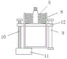
图3是本实用新型中储液瓶安装于加压腔内的示意图(未加压);Fig. 3 is the schematic diagram (not pressurized) of the liquid storage bottle installed in the pressurized chamber in the present invention;
图4是本实用新型中储液瓶安装于加压腔内的示意图(加压);4 is a schematic diagram (pressurized) of the liquid storage bottle installed in the pressurized cavity in the present invention;
图5是本实用新型中锁扣锁紧第一连接头与第三连接头的示意图;Fig. 5 is the schematic diagram of locking the first connector and the third connector in the present utility model;
图6是本实用新型中支架的结构示意图;Fig. 6 is the structural representation of the bracket in the present utility model;
图7是本实用新型中控制装置的电路原理图。FIG. 7 is a circuit schematic diagram of the control device in the present invention.
其中,1.手柄;101.第一按钮;102.旋钮;103.第二按钮;2.加压腔;3.防护罩;4.螺纹管;401.第一连接头;402.锁扣;5.储液瓶;601.第二连接头;602.第三连接头;603.输液管;7.电源线;8.支架;9.光杆;10.螺纹杆;11.步进电机;12.推板。101. The first button; 102. The knob; 103. The second button; 2. The pressurized cavity; 3. The protective cover; 4. The threaded pipe; 401. The first connector; 5. Liquid storage bottle; 601. Second connector; 602. Third connector; 603. Infusion tube; 7. Power cord; 8. Bracket; 9. Polished rod; 10. Threaded rod; 11. Stepper motor; 12 .Push plate.
具体实施方式Detailed ways
下面结合附图及实施例对本实用新型进行详细的说明。The present utility model will be described in detail below with reference to the accompanying drawings and embodiments.
如图1-7所示,一种可调节手握式阴道冲洗器,包括储液瓶5、导流装置、加压装置、控制装置;所述储液瓶5本体为柔性塑料材质且其表面向外形成多圈凸起结构,储液瓶5瓶口为管状且其外壁形成外螺纹;所述导流装置包括输液管603和螺纹管4,输液管603内置于螺纹管4,所述螺纹管4的一端连接加压腔2的前端;所述输液管603两端分别固定有第二连接头601和第三连接头602,第二连接头601和第三连接头602均为管状结构,第二连接头601的内壁形成内螺纹,第三连接头602的外壁形成外螺纹;所述第二连接头601连接储液瓶5瓶口,第三连接头602通过锁扣402锁紧在螺纹管4另一端的第一连接头401上;所述加压装置包括手柄1和加压腔2,加压腔2内置横放的U型支架8;所述支架8的两臂上均形成供推板12穿过的条形缺口,支架8的两侧分别设有螺纹杆10和光杆9,所述光杆9两端固定于加压腔2内部,螺纹杆10一端连接步进电机11的转子,另一端通过轴承座固定于加压腔2内部;螺纹杆10和光杆9分别从推板12的两端贯穿推板12;所述控制装置驱动步进电机11正转或反转;所述手柄上设有多个用于操作本装置的按钮。As shown in Figures 1-7, an adjustable hand-held vaginal irrigator includes a
所述螺纹管4为金属材质,通过外力弯折螺纹管4改变其形状。The threaded
所述锁扣402为圆柱形空心结构且空心部分形成内螺纹,顶端的空心部分嵌套第三连接头602,底端的空心部分嵌套第一连接头401,所述第一连接头401的外壁形成外螺纹。The
所述控制装置包括主控制器,主控制器通过电机驱动模块控制步进电机11正转或反转,控制装置的基本原理如图7所示。所述手柄1上的按钮包括向主控制器输出开关量的第一按钮101和第二按钮103;手柄1表面还设有旋钮102,旋钮102与内置于手柄1的滑动变阻器R1相联动,滑动变阻器的可变端子连接主控制器内置的AD模块的输入引脚。旋钮102不同的档位对应不同的AD值(即经过分压后R1的可变端子与GND之间的电压的AD值),故主控制器根据当前AD值可判断旋钮102的档位,旋钮102的档位用于对应不同的出液速度,即不同的步进电机11转速。The control device includes a main controller, and the main controller controls the forward or reverse rotation of the stepping
所述手柄1内置用于为控制装置和步进电机11供电的电源模块,电源模块的输入端通过手柄尾部的电源线7连接AC-DC电源适配器。适配器为AC220V-DC12V。The
所述加压腔2顶部设有盖板,打开盖板用于放入或取出储液瓶5,加压腔2内的储液瓶5置于支架8的两臂之间,推板12位于储液瓶5和支架8的底板之间。The top of the pressurizing
所述加压腔2的后端连接手柄1。The rear end of the
所述加压腔2的前端固定有伞形的防护罩3,当冲洗时,洗液冲击到患者身体难免会有液珠飞溅,防护罩3可以一定程度上遮挡液珠溅射到医师身上。An umbrella-shaped
储液瓶5类似于弹簧的特殊结构,使得其容积容易改变。The special structure of the
推板12挤压储液瓶5的原理为:当步进电机11正向转动时,带动螺纹杆10正向转动,推板12与螺纹杆10通过螺纹孔配合,故推板12会沿着螺纹杆向前移动,同时由于光杆9的限制,推板12不会发生转动。推板12向前移动时,从储液瓶5底部挤压储液瓶5使之形变,发生如图3和图4所示的变化,过程中,储液瓶5的容积不断变小,内部的洗液被挤出,由于步进电机11的转速可以精确控制,故推板12的移动速度可精确控制,从而容易控制洗液的流量和流速。同理,当步进电机11反向转动时,推板12反向移动。The principle that the
主控制器使用STC15WS408A型号单片机,电机驱动芯片使用L298N型号,主控制器通过GPIO管脚连接电机驱动芯片的控制脚。步进电机11使用42HB34F08B型号,步进电机位于加压腔2内并部署于其尾部,第一按钮101和第二按钮103分别与一个按钮开关联动(即图7中的K1和K2),开关一端通过电阻连接GND,另一端连接主控制器的GPIO管脚,当开关按下时,GPIO检测为低电平,未按下时,GPIO内置弱上拉,故检测为高电平,由此可判断第一按钮101和第二按钮103是否按下。The main controller uses the STC15WS408A type single chip microcomputer, the motor driver chip uses the L298N type, and the main controller connects the control pins of the motor driver chip through the GPIO pins. The
设定第一按钮101按下时,主控制器驱动电机正转,第二按钮103按下时,主控制器驱动电机反转,两按钮同时按下,电机驱动推板12回到“0点”,即其行程中里U型支架8底板最近的点。It is set that when the
本装置的使用方法为:How to use this device:
(1)接通电源,同时按下第一按钮101和第二按钮103,使推板12位置归零。(1) Turn on the power and press the
(2)使用注射器向储液瓶5中灌装一定剂量的洗液,将输液管603一端的第二连接头601拧在储液瓶5的瓶口,并将加压腔2顶部的盖板打开,将储液瓶5放入加压腔2内,将输液管603另一端从螺纹管4中穿过,第三连接头602自螺纹管4的末端穿出,如图5所示,使用锁扣402锁紧第三连接头602和螺纹管4末端的第一连接头401,盖上加压腔2的盖板。(完成步骤2之前,需保持储液瓶5的瓶口向上,防止洗液流出)。(2) Use a syringe to fill a certain dose of lotion into the
(3)调整螺纹管4的角度,使之适合医师操作。(3) Adjust the angle of the threaded
(4)调整旋钮102,设定出液速度,按下第一按钮101,开始冲洗。(4) Adjust the
对于本领域技术人员而言,显然本实用新型不限于上述示范性实施例的细节,而且在不背离本实用新型的精神或基本特征的情况下,能够以其他的具体形式实现本实用新型。因此,无论从哪一点来看,均应将实施例看作是示范性的,而且是非限制性的,本实用新型的范围由所附权利要求而不是上述说明限定,因此旨在将落在权利要求的等同要件的含义和范围内的所有变化囊括在本实用新型内。不应将权利要求中的任何附图标记视为限制所涉及的权利要求。It will be apparent to those skilled in the art that the present invention is not limited to the details of the above-described exemplary embodiments, and that the present invention may be implemented in other specific forms without departing from the spirit or essential characteristics of the present invention. Therefore, the embodiments are to be considered in all respects as exemplary and not restrictive, and the scope of the present invention is defined by the appended claims rather than the foregoing description, and it is therefore intended that the All changes within the meaning and range of the required equivalents are embraced within the present invention. Any reference signs in the claims shall not be construed as limiting the involved claim.
Claims (8)
Priority Applications (1)
| Application Number | Priority Date | Filing Date | Title |
|---|---|---|---|
| CN201921744817.4UCN211096546U (en) | 2019-10-17 | 2019-10-17 | Adjustable hand-held vaginal irrigator |
Applications Claiming Priority (1)
| Application Number | Priority Date | Filing Date | Title |
|---|---|---|---|
| CN201921744817.4UCN211096546U (en) | 2019-10-17 | 2019-10-17 | Adjustable hand-held vaginal irrigator |
Publications (1)
| Publication Number | Publication Date |
|---|---|
| CN211096546Utrue CN211096546U (en) | 2020-07-28 |
Family
ID=71713564
Family Applications (1)
| Application Number | Title | Priority Date | Filing Date |
|---|---|---|---|
| CN201921744817.4UExpired - Fee RelatedCN211096546U (en) | 2019-10-17 | 2019-10-17 | Adjustable hand-held vaginal irrigator |
Country Status (1)
| Country | Link |
|---|---|
| CN (1) | CN211096546U (en) |
Cited By (1)
| Publication number | Priority date | Publication date | Assignee | Title |
|---|---|---|---|---|
| CN112245696A (en)* | 2020-10-16 | 2021-01-22 | 张启新 | Anus rectum drainage flusher |
- 2019
- 2019-10-17CNCN201921744817.4Upatent/CN211096546U/ennot_activeExpired - Fee Related
Cited By (1)
| Publication number | Priority date | Publication date | Assignee | Title |
|---|---|---|---|---|
| CN112245696A (en)* | 2020-10-16 | 2021-01-22 | 张启新 | Anus rectum drainage flusher |
Similar Documents
| Publication | Publication Date | Title |
|---|---|---|
| CN112316239A (en) | Switching device of standby supply passage for intravenous infusion | |
| CN211096546U (en) | Adjustable hand-held vaginal irrigator | |
| CN111714252A (en) | A valve delivery device | |
| CN111135437A (en) | Oral cavity medication device and use method thereof | |
| CN200991440Y (en) | Cystis suction pump | |
| CN201710721U (en) | Vagina treatment device integrating scouring and imbibing | |
| CN206026464U (en) | Trinity oral cavity flusher | |
| CN208893325U (en) | Handheld Electric Pulse Flushing Positive Pressure Sealer | |
| CN117018333B (en) | Tumor thermal perfusion chemotherapy steady voltage adjusting device | |
| CN211513093U (en) | Otolaryngology clinical medicine device that spouts | |
| CN211561375U (en) | Abdominal cavity vein device of dosing of chemotherapy medicine | |
| CN201248802Y (en) | Ophthalmic operation-used synchronous and isometrical injection and suction device | |
| CN112138245A (en) | A self-feedback pain relief system | |
| CN214632389U (en) | Tooth root canal washing unit | |
| CN215608391U (en) | Electric contrast medium injector | |
| CN103565634B (en) | Nasal Passage Irrigation Catheter Set | |
| CN209917050U (en) | Paediatrics nursing is with throat ware of dosing | |
| CN211512881U (en) | Enema device for adults in infectious department | |
| CN210698369U (en) | Novel urinary catheter for bladder irrigation | |
| CN210541905U (en) | Telescopic oral cavity nursing device | |
| CN222238446U (en) | A household Chinese medicine enema device | |
| CN220370226U (en) | Electric abdominal cavity drainage device | |
| CN217960367U (en) | oral cleaning device | |
| CN213489804U (en) | Flushing device for middle ear surgery | |
| CN220801670U (en) | Anesthesia catheter with function of regulating anesthesia flow |
Legal Events
| Date | Code | Title | Description |
|---|---|---|---|
| GR01 | Patent grant | ||
| GR01 | Patent grant | ||
| CF01 | Termination of patent right due to non-payment of annual fee | Granted publication date:20200728 |