CN211077644U - A kind of wood group automatic distributing device - Google Patents
A kind of wood group automatic distributing deviceDownload PDFInfo
- Publication number
- CN211077644U CN211077644UCN201921464969.9UCN201921464969UCN211077644UCN 211077644 UCN211077644 UCN 211077644UCN 201921464969 UCN201921464969 UCN 201921464969UCN 211077644 UCN211077644 UCN 211077644U
- Authority
- CN
- China
- Prior art keywords
- moving
- distribution
- frame
- lifting
- automatic
- Prior art date
- Legal status (The legal status is an assumption and is not a legal conclusion. Google has not performed a legal analysis and makes no representation as to the accuracy of the status listed.)
- Expired - Fee Related
Links
Images


Landscapes
- Feeding Of Workpieces (AREA)
Abstract
Translated fromChinese
Description
Translated fromChinese技术领域technical field
本实用新型涉及木工加工自动分料技术领域,尤其涉及一种木料成组自动分料装置。The utility model relates to the technical field of automatic material distribution in woodworking processing, in particular to an automatic material distribution device for groups of wood.
背景技术Background technique
门边挺加工过程中一般是根据需要,人工单件木料上料,人工放置慢,效率低;现采用机械臂夹取自动放置一排门边挺在前方皮带输送台上,根据门边挺加工的需要一次分若干个加工,为实现连续成组自动分料。因此,一种能够木料成组自动分料装置越来越受到人们的青睐。In the process of door edge processing, it is generally necessary to manually load a single piece of wood, manual placement is slow, and the efficiency is low; now a row of door edge brackets are automatically placed on the front belt conveyor table by mechanical arm clamping, and processed according to the door edge bracket. It needs to be divided into several processing at a time, in order to achieve continuous automatic grouping. Therefore, an automatic distributing device capable of grouping wood is more and more popular.
如何解决上述技术问题为本实用新型面临的课题。How to solve the above technical problems is the subject of the present invention.
实用新型内容Utility model content
本实用新型的目的在于提供一种木料成组自动分料装置。The purpose of the utility model is to provide an automatic material distributing device in groups of wood.
本实用新型是通过如下措施实现的:一种木料成组自动分料装置,包括机架,设置在所述机架上的输送部件,位于所述输送部件下方,设置在所述机架上的若干个托辊升降机构、分料托板结构。The utility model is realized by the following measures: an automatic material distributing device for groups of wood, comprising a frame, a conveying part arranged on the frame, located below the conveying part, and a conveying part arranged on the frame Several roller lifting mechanisms and material distribution pallet structures.
其中,输送部件包括输送履带和驱动输送履带的传动机构;具体包括相对设置的两组固定侧板,设置在每一组固定侧板之间的两传动齿轮,由两传动齿轮传动的横向输送履带,驱动其中一个传动齿轮转动的驱动电机。Among them, the conveying component includes a conveying crawler belt and a transmission mechanism for driving the conveying crawler belt; specifically, it includes two sets of fixed side plates arranged opposite to each other, two transmission gears arranged between each group of fixed side plates, and a transverse conveying crawler driven by the two transmission gears. , the drive motor that drives one of the transmission gears to rotate.
作为本实用新型提供的一种木料成组自动分料装置进一步优化方案,所述木料成组自动分料装置还包括设置在所述机架上的夹手移动横梁,位于所述夹手移动横梁上,沿所述夹手移动横梁的导轨运动的木料夹手组件,设置在所述夹手移动横梁上的固定靠山部件,和安装于所述托辊升降机构上的活动靠山部件。As a further optimization scheme of the automatic grouping of wood materials provided by the utility model, the automatic grouping of wood materials also includes a gripper moving crossbeam arranged on the frame, located on the gripper moving crossbeam On the other hand, a wood gripper assembly that moves along the guide rails of the gripper moving beam, a fixed backer member arranged on the gripper moving beam, and a movable backer member mounted on the idler lifting mechanism.
作为本实用新型提供的一种木料成组自动分料装置进一步优化方案,所述木料夹手组件包括设置在所述夹手移动横梁一端的伺服电机,由所述伺服电机驱动的滚珠丝杠副,连接于所述滚珠丝杠副上的导向座,所述导向座底面的滑块与所述夹手移动横梁的导轨相互滑动配合,设置在所述导向座一侧的夹手气缸,铰接于所述夹手气缸动力杆端部的摆臂,与所述摆臂驱动端活动连接的上夹臂,通过夹手气缸驱动所述上夹臂和下夹臂的夹持开合。As a further optimization scheme of the automatic wood grouping device provided by the present invention, the wood gripper assembly includes a servo motor arranged at one end of the gripper moving beam, and a ball screw pair driven by the servo motor. , connected to the guide seat on the ball screw pair, the sliding block on the bottom surface of the guide seat and the guide rail of the gripper moving beam are slidingly matched with each other, and the gripper cylinder arranged on one side of the guide seat is hinged on the The swing arm at the end of the power rod of the gripper cylinder, and the upper gripper arm movably connected with the drive end of the swing arm, are driven by the gripper cylinder to open and close the upper gripper arm and the lower gripper arm.
作为本实用新型提供的一种木料成组自动分料装置进一步优化方案,所述托辊升降机构包括安装在所述机架上的托辊升降气缸,设置在所述托辊升降气缸升降杆上的托辊底板,设置在所述托辊底板上的导向杆,以及设置在所述托辊底板的两支撑板上的托辊。As a further optimization scheme of the automatic wood grouping device provided by the utility model, the roller lifting mechanism includes a roller lifting cylinder installed on the frame, which is arranged on the lifting rod of the idler lifting cylinder The base plate of the idler roller, the guide rods arranged on the base plate of the idler roller, and the idler rollers arranged on the two support plates of the base plate of the idler roller.
作为本实用新型提供的一种木料成组自动分料装置进一步优化方案,所述分料托板结构包括设置在所述机架上的分料步进电机,与所述分料步进电机输出轴同轴的分料丝杠,连接在所述分料丝杠移动螺母上的宽度移动型材,连接在所述宽度移动型材两端的分料移动导向组件,设置在所述机架上,用于驱动所述分料移动导向组件升降的升降部件,以及设置在所述升降部件托板上方的升降型材。As a further optimization scheme of the automatic wood grouping device provided by the present invention, the material-distributing pallet structure includes a material-distribution stepper motor arranged on the frame, and the output of the material-distribution stepper motor A material distribution screw with a coaxial shaft, a width moving profile connected to the moving nut of the material distribution screw, and a material distribution moving guide assembly connected at both ends of the width moving profile are arranged on the frame and are used for Lifting components that drive the moving guide assembly for lifting and lowering, and lifting profiles arranged above the supporting plates of the lifting components.
作为本实用新型提供的一种木料成组自动分料装置进一步优化方案,所述分料移动导向组件由连接于所述宽度移动型材上的轴承座,设置在所述轴承座上的分料移动导向轴,设置在所述分料移动导向轴驱动端的分料托板组成。As a further optimization scheme of the automatic grouping of wood materials provided by the utility model, the material-distributing moving guide assembly is moved by a bearing seat connected to the width moving profile, and a material-separating device arranged on the bearing seat moves The guide shaft is composed of a material distribution support plate arranged at the driving end of the material distribution moving guide shaft.
作为本实用新型提供的一种木料成组自动分料装置进一步优化方案,所述升降部件包括连接在所述机架上的托架,设置在所述托架上的升降气缸,由所述升降气缸驱动的支撑架,所述支撑架的横向托板用于支撑所述宽度移动型材。As a further optimization scheme of a wood group automatic distributing device provided by the present invention, the lifting component includes a bracket connected to the frame, a lifting cylinder arranged on the bracket, and the lifting component is connected to the bracket. A cylinder-driven support frame, the transverse pallet of the support frame is used to support the width moving profiles.
作为本实用新型提供的一种木料成组自动分料装置进一步优化方案,所述活动靠山部件包括连接于所述托辊底板上的侧夹紧气缸,设置在所述侧夹紧气缸活塞杆上的固定板,所述固定板上设滚轮。As a further optimization scheme of the automatic grouping device for wood material provided by the present invention, the movable backer component includes a side clamping cylinder connected to the bottom plate of the idler, and is arranged on the piston rod of the side clamping cylinder The fixed plate is provided with rollers.
作为本实用新型提供的一种木料成组自动分料装置进一步优化方案,所述固定靠山部件为沿所述夹手移动横梁一侧等间距设置的若干个滚轮靠山,所述滚轮靠山的转轴转动连接于在所述夹手移动横梁上。As a further optimization scheme of the automatic wood grouping device provided by the present invention, the fixed backer component is a plurality of roller backers arranged at equal intervals along one side of the gripper moving beam, and the rotating shaft of the roller backer rotates Connected to the gripper moving beam.
本实用新型的有益效果:本实用新型是通过分料步进电机带动分料丝杠上的螺母,螺母固定的宽度移动型材,宽度移动型材带动分料移动导向轴使得分料托板在宽度方向移动,确定需要夹取的工件的宽度,升降气缸推动其动力杆上的支撑架带动升降型材上升,进而升降型材推动其两端上方的分料移动导向轴上升的同时带动分料托板上升的一定高度,接着托辊升降气缸推动托辊再将分料托板上的工件上升到木料夹手组件要夹取的高度,然后侧夹紧气缸推动活动靠山部件的滚轮靠山处于对应的宽度,其与固定靠山部件一起将工件夹紧,防止工件宽度偏移,启动伺服电机,滚珠丝杠副转动带动导向座沿夹手移动横梁移动,夹手气缸动力杆驱动摆臂带动上夹臂相对于下夹臂打开,夹取移动过来的工件,再将已经夹取的工件沿夹手移动横梁移动,把工件送到下一个加工台上,进而实现木料成组自动分料,克服了原有的人工上料效率低的问题。Beneficial effects of the utility model: The utility model drives the nut on the material-distributing lead screw through the material-distribution stepping motor, the width of the nut is fixed to move the profile, and the width-moving profile drives the material-distribution to move the guide shaft so that the material-distribution pallet moves in the width direction. Move, determine the width of the workpiece to be clamped, the lifting cylinder pushes the support frame on its power rod to drive the lifting profile to rise, and then the lifting profile pushes the material distribution guide shaft above its two ends to rise, and drives the material distribution support plate to rise. At a certain height, then the roller lift cylinder pushes the idler, and then the workpiece on the distribution pallet is raised to the height to be clamped by the wood gripper assembly, and then the side clamping cylinder pushes the roller backer of the movable backer to the corresponding width. Clamp the workpiece together with the fixed backing component to prevent the width of the workpiece from shifting, start the servo motor, the ball screw pair rotates to drive the guide seat to move along the gripper moving beam, and the gripper cylinder power rod drives the swing arm to drive the upper gripper arm relative to the lower gripper. The clamping arm is opened, and the moving workpiece is clamped, and then the clamped workpiece is moved along the moving beam of the clamping hand, and the workpiece is sent to the next processing table, thereby realizing automatic grouping of wood materials, which overcomes the original manual labor. The problem of low feeding efficiency.
附图说明Description of drawings
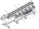
图1为本实用新型实施例的整体结构示意图。FIG. 1 is a schematic diagram of the overall structure of an embodiment of the present invention.
图2为本实用新型实施例的局部结构示意图。FIG. 2 is a schematic diagram of a partial structure of an embodiment of the present invention.
图3为本实用新型实施例的局部结构示意图。3 is a schematic diagram of a partial structure of an embodiment of the present invention.
图4为图2或者图3的主视图。FIG. 4 is a front view of FIG. 2 or FIG. 3 .
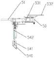
图5为本实用新型实施例中分料托板结构的结构示意图。FIG. 5 is a schematic structural diagram of a material distribution pallet structure in an embodiment of the present invention.
图6为本实用新型实施例中分料托板结构的结构示意图。FIG. 6 is a schematic structural diagram of a material distribution pallet structure in an embodiment of the present invention.
图7为图5或图6的侧视图。FIG. 7 is a side view of FIG. 5 or FIG. 6 .
图8为本实用新型实施例中托辊升降机构与活动靠山部件位置关系的结构示意图。FIG. 8 is a schematic structural diagram of the positional relationship between the roller lifting mechanism and the movable backer component in the embodiment of the present invention.
图9为本实用新型实施例中托辊升降机构与活动靠山部件位置关系的结构示意图。FIG. 9 is a schematic structural diagram of the positional relationship between the roller lifting mechanism and the movable backer component in the embodiment of the present invention.
其中,附图标记为:1、机架;2、夹手移动横梁;3、木料夹手组件;30、伺服电机;31、滚珠丝杠副;32、导向座;33、夹手气缸;34、摆臂;35、夹臂;36、下夹臂;4、托辊升降机构;40、托辊升降气缸;41、托辊底板;42、导向杆;410、两支撑板;43、托辊;5、分料托板结构;50、料步进电机;51、分料丝杠;52、宽度移动型材;53、分料移动导向组件;54、升降部件;55、升降型材;530、轴承座530;531、分料移动导向轴;532、分料托板;540、托架;541、升降气缸;542、支撑架;6、活动靠山部件;60、侧夹紧气缸;61、滚轮;7、固定靠山部件;8、输送部件。Wherein, the reference signs are: 1, frame; 2, gripper moving beam; 3, wood gripper assembly; 30, servo motor; 31, ball screw pair; 32, guide seat; 33, gripper cylinder; 34 , swing arm; 35, clamp arm; 36, lower clamp arm; 4, idler lift mechanism; 40, idler lift cylinder; 41, idler bottom plate; 42, guide rod; 410, two support plates; 43, idler ;5, material distribution pallet structure; 50, material stepper motor; 51, material distribution screw; 52, width moving profiles; 53, material distribution moving guide components; 54, lifting parts; 55, lifting profiles; 530, bearings Seat 530; 531, material distribution moving guide shaft; 532, material distribution support plate; 540, bracket; 541, lift cylinder; 542, support frame; 6, movable backing part; 60, side clamping cylinder; 61, roller; 7. Fixed backing parts; 8. Conveying parts.
具体实施方式Detailed ways
为能清楚说明本方案的技术特点,下面通过具体实施方式,对本方案进行阐述。In order to clearly illustrate the technical features of the solution, the solution will be described below through specific implementations.
参见图1至图9,本实用新型是:一种木料成组自动分料装置,包括机架1,设置在机架1上的输送部件8,位于输送部件8下方,设置在机架1上的若干个托辊升降机构4、分料托板结构5。Referring to FIGS. 1 to 9 , the present utility model is: a wood grouping automatic distributing device, comprising a frame 1, a conveying part 8 arranged on the frame 1, located below the conveying part 8, and arranged on the frame 1 Several
其中,输送部件8是由输送履带,和驱动输送履带的传动机构;具体包括相对设置的两组固定侧板,设置在每一组固定侧板之间的两传动齿轮,由两传动齿轮传动的横向输送履带,驱动其中一个传动齿轮转动的驱动电机。Among them, the conveying part 8 is a transmission mechanism for conveying the crawler belt and driving the conveying crawler belt; it specifically includes two sets of fixed side plates arranged oppositely, and two transmission gears arranged between each group of fixed side plates, which are driven by the two transmission gears. A drive motor that drives one of the transmission gears to rotate the crawler belt laterally.
其中,木料成组自动分料装置还包括设置在机架1上的夹手移动横梁2,位于夹手移动横梁2上,沿夹手移动横梁2的导轨运动的木料夹手组件3,设置在夹手移动横梁2上的固定靠山部件7,和安装于托辊升降机构4上的活动靠山部件6。Wherein, the wood grouping automatic distribution device also includes a
其中,木料夹手组件3包括设置在夹手移动横梁2一端的伺服电机30,由伺服电机30 驱动的滚珠丝杠副31,连接于滚珠丝杠副31上的导向座32,导向座32底面的滑块与夹手移动横梁2的导轨相互滑动配合,设置在导向座32一侧的夹手气缸33,铰接于夹手气缸 33动力杆端部的摆臂34,与摆臂34驱动端活动连接的上夹臂35,通过夹手气缸33驱动上夹臂35和下夹臂36的夹持开合。The
其中,托辊升降机构4包括安装在机架1上的托辊升降气缸40,设置在托辊升降气缸升降杆上的托辊底板,设置在托辊底板上的导向杆,以及设置在托辊底板41的两支撑板410 上的托辊43。Wherein, the
其中,分料托板结构5包括设置在机架1上的分料步进电机50,与分料步进电机50输出轴同轴的分料丝杠51,连接在分料丝杠51移动螺母上的宽度移动型材52,连接在宽度移动型材52两端的分料移动导向组件53,设置在机架1上,用于驱动分料移动导向组件 53升降的升降部件54,以及设置在升降部件54托板上方的升降型材55。Among them, the material distribution
其中,分料移动导向组件53由连接于宽度移动型材52上的轴承座530,设置在轴承座 530上的分料移动导向轴531,设置在分料移动导向轴531驱动端的分料托板532组成。Among them, the distribution
其中,升降部件54包括连接在机架1上的托架540,设置在托架540上的升降气缸541,由升降气缸541驱动的支撑架542,支撑架542的横向托板用于支撑宽度移动型材52。Wherein, the
其中,活动靠山部件6包括连接于托辊底板41上的侧夹紧气缸60,设置在侧夹紧气缸 60活塞杆上的固定板,固定板上设滚轮61。Wherein, the
其中,固定靠山部件7为沿夹手移动横梁2一侧等间距设置的若干个滚轮靠山,滚轮靠山的转轴转动连接于在夹手移动横梁2上。The fixed backing member 7 is a plurality of roller backers arranged at equal intervals along one side of the
本实用新型实际使用时:本实用新型是通过分料步进电机50带动分料丝杠51上的螺母,螺母固定的宽度移动型材52,宽度移动型材52带动分料移动导向轴531使得分料托板532在宽度方向移动,确定需要夹取的工件的宽度,升降气缸541推动其动力杆上的支撑架542带动升降型材55上升,进而升降型材55推动其两端上方的分料移动导向轴531上升的同时带动分料托板532上升的一定高度,接着托辊升降气缸40推动托辊43再将分料托板 532上的工件上升到木料夹手组件3要夹取的高度,然后侧夹紧气缸60推动活动靠山部件 6的滚轮靠山处于对应的宽度,其与固定靠山部件7一起将工件夹紧,启动伺服电机,滚珠丝杠副31转动带动导向座32沿夹手移动横梁2移动,夹手气缸33动力杆驱动摆臂带动上夹臂35相对于下夹臂36打开,夹取移动过来的工件,再将已经夹取的工件沿夹手移动横梁2移动,把工件送到下一个加工台上。When the utility model is actually used: the utility model drives the nut on the material-distributing
本实用新型未经描述的技术特征可以通过或采用现有技术实现,在此不再赘述,当然,上述说明并非是对本实用新型的限制,本实用新型也并不仅限于上述举例,本技术领域的普通技术人员在本实用新型的实质范围内所做出的变化、改型、添加或替换,也应属于本实用新型的保护范围。The undescribed technical features of the present invention can be realized by or using the prior art, and will not be repeated here. Of course, the above descriptions are not intended to limit the present invention, and the present invention is not limited to Changes, modifications, additions or substitutions made by those of ordinary skill within the essential scope of the present invention should also belong to the protection scope of the present invention.
Claims (7)
Priority Applications (1)
| Application Number | Priority Date | Filing Date | Title |
|---|---|---|---|
| CN201921464969.9UCN211077644U (en) | 2019-09-04 | 2019-09-04 | A kind of wood group automatic distributing device |
Applications Claiming Priority (1)
| Application Number | Priority Date | Filing Date | Title |
|---|---|---|---|
| CN201921464969.9UCN211077644U (en) | 2019-09-04 | 2019-09-04 | A kind of wood group automatic distributing device |
Publications (1)
| Publication Number | Publication Date |
|---|---|
| CN211077644Utrue CN211077644U (en) | 2020-07-24 |
Family
ID=71632861
Family Applications (1)
| Application Number | Title | Priority Date | Filing Date |
|---|---|---|---|
| CN201921464969.9UExpired - Fee RelatedCN211077644U (en) | 2019-09-04 | 2019-09-04 | A kind of wood group automatic distributing device |
Country Status (1)
| Country | Link |
|---|---|
| CN (1) | CN211077644U (en) |
Cited By (3)
| Publication number | Priority date | Publication date | Assignee | Title |
|---|---|---|---|---|
| CN110562737A (en)* | 2019-09-04 | 2019-12-13 | 南通跃通数控设备股份有限公司 | Automatic material distributing device for grouping wood materials |
| CN112061777A (en)* | 2020-09-07 | 2020-12-11 | 国家林业和草原局北京林业机械研究所 | Clamping device for bamboo tube classification |
| CN115026580A (en)* | 2022-07-22 | 2022-09-09 | 南通跃通数控设备股份有限公司 | Door frame clamping device capable of automatically adjusting upper reference surface |
- 2019
- 2019-09-04CNCN201921464969.9Upatent/CN211077644U/ennot_activeExpired - Fee Related
Cited By (5)
| Publication number | Priority date | Publication date | Assignee | Title |
|---|---|---|---|---|
| CN110562737A (en)* | 2019-09-04 | 2019-12-13 | 南通跃通数控设备股份有限公司 | Automatic material distributing device for grouping wood materials |
| CN110562737B (en)* | 2019-09-04 | 2024-04-30 | 南通跃通数控设备股份有限公司 | Automatic timber grouping and distributing device |
| CN112061777A (en)* | 2020-09-07 | 2020-12-11 | 国家林业和草原局北京林业机械研究所 | Clamping device for bamboo tube classification |
| CN115026580A (en)* | 2022-07-22 | 2022-09-09 | 南通跃通数控设备股份有限公司 | Door frame clamping device capable of automatically adjusting upper reference surface |
| CN115026580B (en)* | 2022-07-22 | 2024-01-02 | 南通跃通数控设备股份有限公司 | Door frame clamping device capable of automatically adjusting upper-mounted datum plane |
Similar Documents
| Publication | Publication Date | Title |
|---|---|---|
| CN211077644U (en) | A kind of wood group automatic distributing device | |
| CN108082880B (en) | Full-automatic production line of multilayer plywood | |
| CN111268444A (en) | Automatic stacking device in UV floor production | |
| CN203739280U (en) | A kind of plate automatic processing machine | |
| CN113001690A (en) | Bamboo and wood splicing production line and splicing method thereof | |
| CN109051797B (en) | Plate-shaped material feeding structure and plate-shaped material conveying system | |
| CN112478600A (en) | Plate conveying butt joint device | |
| CN109230532B (en) | Plate-shaped material conveying system and plate-shaped material conveying method | |
| CN111571726A (en) | a wood cutting machine | |
| CN215618694U (en) | Bamboo wood concatenation production line | |
| CN119114384A (en) | A conveying device for quantitative glue coating equipment | |
| CN109910111A (en) | Feeding device of sheet processing equipment | |
| CN212287997U (en) | Feeding mechanism of a wood cutting machine | |
| CN216835992U (en) | Plate storage device | |
| CN111590694A (en) | Feeding mechanism of timber cutting machine | |
| CN215401566U (en) | Plate hot-pressing production line | |
| CN212761414U (en) | Aluminum profile machining is with cutting transfer device | |
| CN209097563U (en) | A furniture board conveying device based on adjustable lift | |
| CN110562737B (en) | Automatic timber grouping and distributing device | |
| CN209880562U (en) | A feeding device with adjustable width and board return function | |
| CN113526144A (en) | Silicon steel sheet balanced stacking and distributing system | |
| CN221499707U (en) | Multichannel bullet floodgate automatic feeding machine | |
| CN219274832U (en) | Metal plate frame bed for laser cutting bed | |
| CN221939248U (en) | A plate conveying track for plate processing | |
| CN221216136U (en) | Upper plate device for plates |
Legal Events
| Date | Code | Title | Description |
|---|---|---|---|
| GR01 | Patent grant | ||
| GR01 | Patent grant | ||
| CF01 | Termination of patent right due to non-payment of annual fee | Granted publication date:20200724 |