CN211066839U - Endoscopic tunnel suture clip - Google Patents
Endoscopic tunnel suture clipDownload PDFInfo
- Publication number
- CN211066839U CN211066839UCN201920901776.9UCN201920901776UCN211066839UCN 211066839 UCN211066839 UCN 211066839UCN 201920901776 UCN201920901776 UCN 201920901776UCN 211066839 UCN211066839 UCN 211066839U
- Authority
- CN
- China
- Prior art keywords
- shell
- control
- groove
- clamping
- suture clip
- Prior art date
- Legal status (The legal status is an assumption and is not a legal conclusion. Google has not performed a legal analysis and makes no representation as to the accuracy of the status listed.)
- Active
Links
- 230000000712assemblyEffects0.000claimsabstractdescription12
- 238000000429assemblyMethods0.000claimsabstractdescription12
- 230000001681protective effectEffects0.000claimsdescription43
- 125000006850spacer groupChemical group0.000claimsdescription33
- 230000000149penetrating effectEffects0.000claimsdescription6
- 230000008878couplingEffects0.000claims1
- 238000010168coupling processMethods0.000claims1
- 238000005859coupling reactionMethods0.000claims1
- 230000002452interceptive effectEffects0.000claims1
- 239000007787solidSubstances0.000claims1
- 230000007547defectEffects0.000description45
- 206010052428WoundDiseases0.000description38
- 208000027418Wounds and injuryDiseases0.000description38
- 238000010586diagramMethods0.000description31
- 238000000034methodMethods0.000description5
- 238000004519manufacturing processMethods0.000description4
- 230000004048modificationEffects0.000description4
- 238000012986modificationMethods0.000description4
- 238000005516engineering processMethods0.000description3
- 230000002439hemostatic effectEffects0.000description3
- 210000004400mucous membraneAnatomy0.000description3
- 238000006748scratchingMethods0.000description3
- 230000002393scratching effectEffects0.000description3
- 239000002184metalSubstances0.000description2
- 239000004033plasticSubstances0.000description2
- 230000008569processEffects0.000description2
- 208000002699Digestive System NeoplasmsDiseases0.000description1
- 208000018522Gastrointestinal diseaseDiseases0.000description1
- 208000012671Gastrointestinal haemorrhagesDiseases0.000description1
- 206010018001Gastrointestinal perforationDiseases0.000description1
- 239000004677NylonSubstances0.000description1
- 238000005452bendingMethods0.000description1
- 230000007797corrosionEffects0.000description1
- 238000005260corrosionMethods0.000description1
- 230000002950deficientEffects0.000description1
- 230000001079digestive effectEffects0.000description1
- 238000011846endoscopic investigationMethods0.000description1
- 238000001839endoscopyMethods0.000description1
- 230000002496gastric effectEffects0.000description1
- 208000030304gastrointestinal bleedingDiseases0.000description1
- 230000006872improvementEffects0.000description1
- 238000002357laparoscopic surgeryMethods0.000description1
- 238000002350laparotomyMethods0.000description1
- 238000002324minimally invasive surgeryMethods0.000description1
- 229920001778nylonPolymers0.000description1
- 230000008439repair processEffects0.000description1
Images


Classifications
- A—HUMAN NECESSITIES
- A61—MEDICAL OR VETERINARY SCIENCE; HYGIENE
- A61B—DIAGNOSIS; SURGERY; IDENTIFICATION
- A61B17/00—Surgical instruments, devices or methods
- A61B17/04—Surgical instruments, devices or methods for suturing wounds; Holders or packages for needles or suture materials
- A61B17/0469—Suturing instruments for use in minimally invasive surgery, e.g. endoscopic surgery
- A—HUMAN NECESSITIES
- A61—MEDICAL OR VETERINARY SCIENCE; HYGIENE
- A61B—DIAGNOSIS; SURGERY; IDENTIFICATION
- A61B17/00—Surgical instruments, devices or methods
- A61B17/04—Surgical instruments, devices or methods for suturing wounds; Holders or packages for needles or suture materials
- A61B17/0491—Sewing machines for surgery
- A—HUMAN NECESSITIES
- A61—MEDICAL OR VETERINARY SCIENCE; HYGIENE
- A61B—DIAGNOSIS; SURGERY; IDENTIFICATION
- A61B17/00—Surgical instruments, devices or methods
- A61B17/12—Surgical instruments, devices or methods for ligaturing or otherwise compressing tubular parts of the body, e.g. blood vessels or umbilical cord
- A61B17/122—Clamps or clips, e.g. for the umbilical cord
- A61B17/1227—Spring clips
- A—HUMAN NECESSITIES
- A61—MEDICAL OR VETERINARY SCIENCE; HYGIENE
- A61B—DIAGNOSIS; SURGERY; IDENTIFICATION
- A61B17/00—Surgical instruments, devices or methods
- A61B17/12—Surgical instruments, devices or methods for ligaturing or otherwise compressing tubular parts of the body, e.g. blood vessels or umbilical cord
- A61B17/128—Surgical instruments, devices or methods for ligaturing or otherwise compressing tubular parts of the body, e.g. blood vessels or umbilical cord for applying or removing clamps or clips
- A61B17/1285—Surgical instruments, devices or methods for ligaturing or otherwise compressing tubular parts of the body, e.g. blood vessels or umbilical cord for applying or removing clamps or clips for minimally invasive surgery
- A—HUMAN NECESSITIES
- A61—MEDICAL OR VETERINARY SCIENCE; HYGIENE
- A61B—DIAGNOSIS; SURGERY; IDENTIFICATION
- A61B17/00—Surgical instruments, devices or methods
- A61B17/12—Surgical instruments, devices or methods for ligaturing or otherwise compressing tubular parts of the body, e.g. blood vessels or umbilical cord
- A61B2017/12004—Surgical instruments, devices or methods for ligaturing or otherwise compressing tubular parts of the body, e.g. blood vessels or umbilical cord for haemostasis, for prevention of bleeding
Landscapes
- Health & Medical Sciences (AREA)
- Life Sciences & Earth Sciences (AREA)
- Surgery (AREA)
- Molecular Biology (AREA)
- General Health & Medical Sciences (AREA)
- Biomedical Technology (AREA)
- Heart & Thoracic Surgery (AREA)
- Medical Informatics (AREA)
- Nuclear Medicine, Radiotherapy & Molecular Imaging (AREA)
- Animal Behavior & Ethology (AREA)
- Engineering & Computer Science (AREA)
- Public Health (AREA)
- Veterinary Medicine (AREA)
- Reproductive Health (AREA)
- Vascular Medicine (AREA)
- Surgical Instruments (AREA)
- Endoscopes (AREA)
Abstract
Translated fromChinese
Description
Translated fromChinese技术领域technical field
本实用新型涉及医疗技术领域,具体而言,涉及一种内窥镜孔道缝合夹。The utility model relates to the field of medical technology, in particular to an endoscope hole suture clip.
背景技术Background technique
本实用新型对于背景技术的描述属于与本实用新型相关的相关技术,仅仅是用于说明和便于理解本实用新型的实用新型内容,不应理解为申请人明确认为或推定申请人认为是本实用新型在首次提出申请的申请日的现有技术。The description of the background technology of the present utility model belongs to the related technology related to the present utility model, and is only used to illustrate and facilitate the understanding of the utility model content of the present utility model. The new type of prior art on the filing date of the first application.
随着内镜微创技术发展,以前需要外科开腹或者腹腔镜处理的一些消化道疾病,比如消化道早期肿瘤,均能在消化内镜微创下治疗。在内镜微创手术过程中,消化道粘膜缺损缝合,包括消化道出血及穿孔,是最常见的问题。目前,主要使用的缺损缝合方法有,内镜夹,尼龙绳联合内镜夹荷包缝合及内镜缝合装置(OTSC)。内镜夹使用简单且费用较便宜,但是,对于较大的缺损或者困难部位的缺损难以发挥修补作用。OTSC由国外专家实用新型,费用昂贵,操作较复杂,需要前期的培训才能使用。因此,一种“内窥镜孔道缝合夹”被设计,该设计旨在能简单快捷及有效地对大的消化道缺损及困难操作部位的缺损进行夹持并缝合。With the development of minimally invasive endoscopic techniques, some gastrointestinal diseases that previously required surgical laparotomy or laparoscopy, such as early gastrointestinal tumors, can be treated with minimally invasive digestive endoscopy. During endoscopic minimally invasive surgery, suturing of gastrointestinal mucosal defects, including gastrointestinal bleeding and perforation, is the most common problem. At present, the main defect suturing methods are endoscopic clip, nylon rope combined with endoscopic clip purse-string suture and endoscopic suturing device (OTSC). Endoscope clips are easy to use and inexpensive, but they are difficult to repair for larger defects or defects in difficult parts. OTSC is a utility model developed by foreign experts, which is expensive and complicated to operate, and requires pre-training before it can be used. Therefore, an "endoscopic tunnel suture clip" is designed, which is designed to clamp and suture large alimentary tract defects and defects in difficult-to-operate sites simply, quickly and effectively.
实用新型内容Utility model content
本实用新型提供了一种内窥镜孔道缝合夹包括:外壳,所述外壳上对称地设置有第一滑槽,所述第一滑槽沿所述外壳的轴向设置;夹持芯,所述夹持芯与所述外壳固定连接;两个夹持部,两个夹持部通过转轴安装在所述外壳上,并可相对于所述外壳转动,所述夹持部上设置有第二滑槽,所述第二滑槽包括导向槽和限位槽;和两个控制组件,两个所述控制组件分别与两个所述夹持部连接,两个所述控制组件分别独立控制两个所述夹持部相对于所述夹持芯打开或者闭合,以夹持目标物;其中,所述控制组件包括:滑块,所述滑块设置在所述第二滑槽内,并可在所述第二滑槽内滑动,所述夹持部与所述夹持芯闭合后,所述滑块能够卡入所述限位槽内;和控制件,所述控制件的一端与所述滑块连接,另一端伸出所述外壳,所述控制件的一部分位于所述第一滑槽内,并可在所述第一滑槽内滑动。The utility model provides an endoscope tunnel suture clip, comprising: a casing, on which a first chute is symmetrically arranged, and the first chute is arranged along the axial direction of the casing; a clamping core, the The clamping core is fixedly connected with the outer casing; two clamping parts are mounted on the outer casing through a rotating shaft and can be rotated relative to the outer casing, and a second clamping part is provided on the clamping part. A chute, the second chute includes a guide slot and a limit slot; and two control assemblies, the two control assemblies are respectively connected with the two clamping parts, and the two control assemblies independently control the two Each of the clamping parts is opened or closed relative to the clamping core to clamp the target object; wherein, the control assembly includes: a sliding block, the sliding block is arranged in the second sliding groove, and can be sliding in the second chute, after the clamping part and the clamping core are closed, the sliding block can be clamped into the limiting groove; and a control member, one end of the control member is connected to the The slider is connected, the other end protrudes from the casing, and a part of the control member is located in the first chute and can slide in the first chute.
本实用新型提供的内窥镜孔道缝合夹,两个夹持部均与控制组件连接,且控制组件可以分别控制两个夹持部各自单独相对于夹持芯打开或关闭,从而具有双侧夹持闭合大缺损创面的功能,弥补了大缺损创面通过常规止血夹只能单侧夹持的缺陷,进而可以对大尺寸或困难操作部位缺损创面进行处理。控制件具有一定刚性,从而使滑块与控制件的行程的行程相同,操作者可通过控制件和滑块的配合控制夹持部在较小的范围内开闭,进而实现比较精密的缺损创面。第一滑槽对控制件起到了导向及固定作用,保证了控制件沿固定的方向的稳定运动,避免了控制件滑脱的情况发生,从而保证了产品的使用可靠性。另外,控制件带动滑块滑入限位槽,滑块被限定在限位槽内,使在不需要操作者施加力的情况下,夹持部和夹持芯处于闭合锁定状态,方便操作者进行其他操作;当需要解除该状态,只需操作人员据需要向前用力推控制件,使控制件带动滑块滑出限位槽。In the endoscope tunnel suture clamp provided by the present invention, both clamping parts are connected with the control assembly, and the control assembly can respectively control the two clamping parts to open or close with respect to the clamping core respectively, so as to have a double-sided clamp The function of holding and closing large defect wounds makes up for the defect that large defect wounds can only be held unilaterally by conventional hemostatic clips, so that large-sized or difficult-to-operate defect wounds can be treated. The control part has a certain rigidity, so that the stroke of the slider and the control part are the same. The operator can control the opening and closing of the clamping part in a small range through the cooperation of the control part and the slider, thereby realizing a relatively precise defect wound. . The first chute plays the role of guiding and fixing the control part, ensuring the stable movement of the control part in a fixed direction, avoiding the slippage of the control part, and thus ensuring the reliability of the product. In addition, the control element drives the slider to slide into the limit slot, and the slider is limited in the limit slot, so that the clamping part and the clamping core are in a closed and locked state without the need for the operator to exert force, which is convenient for the operator Perform other operations; when it is necessary to release this state, the operator only needs to push the control piece forward as required, so that the control piece drives the slider to slide out of the limit slot.
可选地,所述外壳上设置有贯穿所述外壳的第一通槽,两个所述夹持部位于所述第一通槽内,所述第一通槽上对称的两个槽壁上分别设置有所述第一滑槽;所述第一滑槽为贯穿所述外壳的通孔。Optionally, the casing is provided with a first through groove penetrating the casing, the two clamping parts are located in the first through groove, and two symmetrical groove walls on the first through groove are provided. The first sliding grooves are respectively provided; the first sliding grooves are through holes penetrating the casing.
可选地,所述外壳包括:固定壳,所述固定壳的一端上设置有第二通槽;和连接壳,所述连接壳设置在所述固定壳的一端,所述连接壳密封所述第二通槽的开口,并与所述第二通槽围成所述第一滑槽。Optionally, the outer casing includes: a fixed casing, one end of the fixed casing is provided with a second through groove; and a connecting casing, the connecting casing is disposed at one end of the fixed casing, and the connecting casing seals the The opening of the second through groove and the second through groove form the first chute.
可选地,所述外壳还包括:壳体,所述壳体上设置有所述第一滑槽;和第一隔片,所述第一隔片固定在所述壳体内,所述第一隔片将所述壳体分割为对称的两个通道,两个所述控制件分别位于两个所述通道内。Optionally, the housing further includes: a housing, the housing is provided with the first chute; and a first spacer, the first spacer is fixed in the housing, the first spacer The spacer divides the housing into two symmetrical channels, and the two control members are respectively located in the two channels.
可选地,所述第一隔片的两侧分别设置有子槽,所述子槽与所述第一滑槽对应设置。Optionally, two sides of the first spacer are respectively provided with sub-slots, and the sub-slots are arranged corresponding to the first chute.
可选地,所述第一隔片的一端设置有转轴孔,所述转轴位于所述转轴孔内;所述第一隔片的另一端对称地设置有插片,所述壳体上设置有与所述插片相配合的插槽。Optionally, one end of the first spacer is provided with a rotating shaft hole, and the rotating shaft is located in the rotating shaft hole; the other end of the first spacer is symmetrically provided with an insert, and the housing is provided with a slot that fits with the insert.
可选地,所述第一滑槽处的所述外壳的侧壁向所述外壳内凹陷形成避让空间。Optionally, the side wall of the casing at the first chute is recessed into the casing to form an escape space.
可选地,所述外壳包括:固定部,所述固定部的一端与所述夹持芯连接,两个所述夹持部分别位于所述固定部的两侧,所述固定部上设置有第三滑槽,所述滑块的一端位于所述第三滑槽内;和连接管,所述连接管与所述固定部的另一端连接;所述第一滑槽设置在所述连接管的内壁上。Optionally, the housing includes: a fixing part, one end of the fixing part is connected with the clamping core, the two clamping parts are respectively located on both sides of the fixing part, and the fixing part is provided with a third chute, one end of the slider is located in the third chute; and a connecting pipe, the connecting pipe is connected with the other end of the fixing part; the first chute is arranged on the connecting pipe on the inner wall.
可选地,所述外壳包括:固定部,所述固定部的一端与所述夹持芯连接,两个所述夹持部分别位于所述固定部的两侧,所述固定部上设置有第三滑槽,所述滑块的一端位于所述第三滑槽内;连接管,所述连接管与所述固定部的另一端连接;和第二隔片,所述第二隔片固定在所述连接管内,所述第二隔片将所述连接管分割为对称的两个通道,所述第二隔片的两侧分别设置有所述第一滑槽,两个所述控制件分别位于两个所述通道内。Optionally, the housing includes: a fixing part, one end of the fixing part is connected with the clamping core, the two clamping parts are respectively located on both sides of the fixing part, and the fixing part is provided with A third chute, one end of the slider is located in the third chute; a connecting pipe, the connecting pipe is connected to the other end of the fixing part; and a second spacer, the second spacer is fixed In the connecting pipe, the second spacer divides the connecting pipe into two symmetrical channels, the first chute is respectively provided on both sides of the second spacer, and the two control members are located in the two said channels, respectively.
可选地,所述外壳包括:固定部,所述固定部的一端与所述夹持芯连接,两个所述夹持部分别位于所述固定部的两侧,所述固定部上设置有第三滑槽,所述滑块的一端位于所述第三滑槽内;和连接管,所述连接管与所述固定部的另一端连接;所述第一滑槽为贯穿所述外壳的通孔。Optionally, the housing includes: a fixing part, one end of the fixing part is connected with the clamping core, the two clamping parts are respectively located on both sides of the fixing part, and the fixing part is provided with a third chute, one end of the sliding block is located in the third chute; and a connecting pipe, the connecting pipe is connected with the other end of the fixing part; the first chute is a part that penetrates through the casing through hole.
可选地,所述控制件包括:连接环,所述连接环套设在所述滑块上;控制杆,所述控制杆的一端与所述连接环固定连接,另一端伸出所述外壳;和滑柱,所述滑柱固定在所述滑块上,所述滑柱位于所述第一滑槽内,并可在所述第一滑槽内滑动。Optionally, the control member includes: a connecting ring, which is sleeved on the slider; a control rod, one end of the control rod is fixedly connected with the connecting ring, and the other end extends out of the casing ; and a sliding column, the sliding column is fixed on the sliding block, the sliding column is located in the first sliding groove, and can slide in the first sliding groove.
可选地,所述连接环上设置有断裂口,所述断裂口位于远离所述连接环与所述控制杆连接处的一端。Optionally, the connecting ring is provided with a breaking opening, and the breaking opening is located at one end away from the connection between the connecting ring and the control rod.
可选地,所述控制件包括:连接片,所述连接片的一端与所述滑块连接;连接环,所述连接环通过连接轴与所述连接片的另一端连接,所述连接轴的一端位于所述第一滑槽内,并可在所述第一滑槽内滑动;和控制杆,所述控制杆的一端与所述连接环固定连接,另一端伸出所述外壳。Optionally, the control member includes: a connecting piece, one end of the connecting piece is connected with the slider; a connecting ring, the connecting ring is connected with the other end of the connecting piece through a connecting shaft, the connecting shaft and a control rod, one end of the control rod is fixedly connected with the connecting ring, and the other end protrudes from the casing.
可选地,所述连接环上设置有断裂区,所述断裂区位于远离所述连接环与所述控制杆连接处的一端,所述断裂区处的所述连接环的宽度小于所述连接环其他区域的宽度。Optionally, the connecting ring is provided with a breaking area, the breaking area is located at an end away from the connection between the connecting ring and the control rod, and the width of the connecting ring at the breaking area is smaller than that of the connection The width of the rest of the ring.
可选地,所述导向槽与所述限位槽连接处设置有限位凸起。Optionally, a limit protrusion is provided at the connection between the guide groove and the limit groove.
可选地,所述导向槽与所述限位槽之间具有夹角。Optionally, there is an included angle between the guide groove and the limiting groove.
可选地,内窥镜孔道缝合夹还包括:保护壳和锁合件,所述保护壳通过所述锁合件与所述外壳可拆卸连接,所述控制杆的另一端穿过所述锁合件伸出所述保护壳;沿所述控制件的运动方向,所述连接环能够与所述锁合件相干涉。Optionally, the endoscope tunnel suture clip further includes: a protective shell and a locking piece, the protective shell is detachably connected to the outer shell through the locking piece, and the other end of the control rod passes through the lock The locking piece protrudes from the protective shell; along the movement direction of the control piece, the connecting ring can interfere with the locking piece.
可选地,所述锁合件包括:固定环,所述固定环的直径小于所述连接环的直径;和多个弹性臂,多个所述弹性臂的一端与所述固定环固定连接,并沿所述固定环的周向设置,所述弹性臂的另一端向所述弹性臂的一侧弯折形成插脚;所述保护壳上设置有多个第一连接孔,所述外壳上设置有多个与所述第一连接孔相对应的第二连接孔;所述锁合件设置在所述保护壳内,所述插脚依次插入所述第一连接孔和所述第二连接孔内,以使所述保护壳与所述外壳固定连接,所述控制件的另一端穿过所述固定环伸出所述保护壳。Optionally, the locking member comprises: a fixing ring, the diameter of the fixing ring is smaller than the diameter of the connecting ring; and a plurality of elastic arms, one end of the plurality of elastic arms is fixedly connected with the fixing ring, and arranged along the circumferential direction of the fixing ring, the other end of the elastic arm is bent to one side of the elastic arm to form a pin; the protective shell is provided with a plurality of first connection holes, and the outer shell is provided with There are a plurality of second connection holes corresponding to the first connection holes; the locking member is arranged in the protective shell, and the pins are inserted into the first connection holes and the second connection holes in sequence , so that the protective shell is fixedly connected with the outer shell, and the other end of the control piece protrudes out of the protective shell through the fixing ring.
可选地,所述锁合件包括:连接架;多个弹性臂,多个所述弹性臂的一端与所述连接架固定连接,所述弹性臂的另一端向所述弹性臂的一侧弯折形成插脚;和两个释放环,两个所述释放环分别套设在两个所述弹性臂上,所述释放环的直径小于所述连接环的直径;所述保护壳上设置有多个第一连接孔,所述外壳上设置有多个与所述第一连接孔相对应的第二连接孔;所述锁合件设置在所述保护壳内,所述插脚依次插入所述第一连接孔和所述第二连接孔内,以使所述保护壳与所述外壳固定连接,所述控制件的另一端穿过所述释放环伸出所述保护壳。Optionally, the locking member includes: a connecting frame; a plurality of elastic arms, one end of the plurality of elastic arms is fixedly connected to the connecting frame, and the other end of the elastic arms faces one side of the elastic arms Bending to form pins; and two release rings, the two release rings are respectively sleeved on the two elastic arms, the diameter of the release rings is smaller than the diameter of the connection rings; the protective shell is provided with a plurality of first connection holes, the casing is provided with a plurality of second connection holes corresponding to the first connection holes; the locking piece is arranged in the protective shell, and the pins are inserted into the into the first connection hole and the second connection hole, so that the protective shell is fixedly connected with the outer shell, and the other end of the control piece protrudes out of the protective shell through the release ring.
可选地,所述保护壳包括弹簧软管和固定管,所述弹簧软管与所述固定管连接,所述固定管上设置有所述第一连接孔。Optionally, the protective case includes a spring hose and a fixing tube, the spring hose is connected to the fixing tube, and the fixing tube is provided with the first connection hole.
本实用新型的附加方面和优点将在下面的描述部分中变得明显,或通过本实用新型的实践了解到。Additional aspects and advantages of the present invention will become apparent in the following section of the description, or learned by practice of the present invention.
附图说明Description of drawings
本实用新型的上述和/或附加的方面和优点从结合下面附图对实施例的描述中将变得明显和容易理解,其中:The above and/or additional aspects and advantages of the present invention will become apparent and readily understood from the following description of embodiments in conjunction with the accompanying drawings, wherein:
图1是本实用新型所述内窥镜孔道缝合夹第一种实施例的结构示意图;1 is a schematic structural diagram of the first embodiment of the endoscope tunnel suture clip according to the present invention;
图2是图1所示内窥镜孔道缝合夹的分解结构示意图;Fig. 2 is the exploded structure schematic diagram of the endoscope tunnel suture clip shown in Fig. 1;
图3是图1所示内窥镜孔道缝合夹的剖视结构示意图;Fig. 3 is the sectional structure schematic diagram of the endoscope tunnel suture clip shown in Fig. 1;
图4是本实用新型所述控制件与夹持部配合第一种实施例的结构示意图;FIG. 4 is a schematic structural diagram of the first embodiment of the control member and the clamping portion of the present invention;
图5是本实用新型所述控制件与夹持部配合第二种实施例的结构示意图;FIG. 5 is a schematic structural diagram of the second embodiment of the control member and the clamping portion of the present invention;
图6是本实用新型所述夹持部第一种实施例的结构示意图;6 is a schematic structural diagram of the first embodiment of the clamping portion of the present invention;
图7是本实用新型所述夹持部第二种实施例的结构示意图;7 is a schematic structural diagram of the second embodiment of the clamping portion of the present invention;
图8是本实用新型所述控制杆与连接环第一种实施例的结构示意图;8 is a schematic structural diagram of the first embodiment of the control rod and the connecting ring according to the present invention;
图9是本实用新型所述控制杆与连接环第二种实施例的结构示意图;9 is a schematic structural diagram of the second embodiment of the control rod and the connecting ring of the present invention;
图10是本实用新型所述锁合件第一种实施例的结构示意图;10 is a schematic structural diagram of the first embodiment of the locking member of the present invention;
图11是本实用新型所述锁合件第二种实施例的结构示意图;Figure 11 is a schematic structural diagram of the second embodiment of the locking member of the present invention;
图12是本实用新型所述内窥镜孔道缝合夹第二种实施例的结构示意图;12 is a schematic structural diagram of the second embodiment of the endoscope tunnel suture clip according to the present invention;
图13是图12所示内窥镜孔道缝合夹的分解结构示意图;Fig. 13 is the exploded structure schematic diagram of the endoscope tunnel suture clip shown in Fig. 12;
图14是图12所示内窥镜孔道缝合夹的剖视结构示意图;Figure 14 is a schematic cross-sectional structural view of the endoscope tunnel suture clip shown in Figure 12;
图15是本实用新型所述内窥镜孔道缝合夹第三种实施例的结构示意图;15 is a schematic structural diagram of the third embodiment of the endoscope tunnel suture clip according to the present invention;
图16是图15所示内窥镜孔道缝合夹的分解结构示意图;Fig. 16 is the exploded structure schematic diagram of the endoscope tunnel suture clip shown in Fig. 15;
图17a是图15所示内窥镜孔道缝合夹的第一方向剖视结构示意图;Figure 17a is a schematic cross-sectional structural diagram of the endoscope tunnel suture clip shown in the first direction shown in Figure 15;
图17b是图15所示内窥镜孔道缝合夹的第二方向剖视结构示意图;Figure 17b is a schematic cross-sectional structural diagram of the endoscope tunnel suture clip shown in Figure 15 in the second direction;
图18是本实用新型所述内窥镜孔道缝合夹第四种实施例的结构示意图;18 is a schematic structural diagram of the fourth embodiment of the endoscope tunnel suture clip according to the present invention;
图19是图18所示内窥镜孔道缝合夹的分解结构示意图;Figure 19 is a schematic diagram of the exploded structure of the endoscope tunnel suture clip shown in Figure 18;
图20是图18所示内窥镜孔道缝合夹的剖视结构示意图;Figure 20 is a schematic cross-sectional view of the endoscope tunnel suture clip shown in Figure 18;
图21是本实用新型所述内窥镜孔道缝合夹第五种实施例的结构示意图;21 is a schematic structural diagram of the fifth embodiment of the endoscope tunnel suture clip according to the present invention;
图22是图21所示内窥镜孔道缝合夹的分解结构示意图;Fig. 22 is the exploded structure schematic diagram of the endoscope tunnel suture clip shown in Fig. 21;
图23是图21所示内窥镜孔道缝合夹的剖视结构示意图;Figure 23 is a schematic cross-sectional view of the endoscope tunnel suture clip shown in Figure 21;
图24是图21中所示固定壳的结构示意图;FIG. 24 is a schematic structural diagram of the fixing case shown in FIG. 21;
图25是本实用新型所述内窥镜孔道缝合夹第六种实施例的结构示意图。25 is a schematic structural diagram of the sixth embodiment of the endoscope tunnel suture clip according to the present invention.
图26是图25所示内窥镜孔道缝合夹的分解结构示意图;Fig. 26 is the exploded structure schematic diagram of the endoscope tunnel suture clip shown in Fig. 25;
图27是图25所示内窥镜孔道缝合夹的剖视结构示意图;Figure 27 is a cross-sectional structural schematic diagram of the endoscope tunnel suture clip shown in Figure 25;
图28是本实用新型所述内窥镜孔道缝合夹第七种实施例的结构示意图。Fig. 28 is a schematic structural diagram of the seventh embodiment of the endoscope tunnel suture clip according to the present invention.
图29是图28所示内窥镜孔道缝合夹的分解结构示意图;Fig. 29 is a schematic diagram of the exploded structure of the endoscope tunnel suture clip shown in Fig. 28;
图30是图28所示内窥镜孔道缝合夹的剖视结构示意图。FIG. 30 is a schematic cross-sectional structural diagram of the endoscope tunnel suture clip shown in FIG. 28 .
其中,图1至图30的附图标记与部件名称之间的对应关系为:Wherein, the corresponding relationship between the reference numerals and component names in Fig. 1 to Fig. 30 is:
夹持芯100,外壳110,固定壳11,连接壳12,第二通槽13,壳体 14,插槽141,第一隔片15,子槽151,转轴孔152,插片153,避让空间 16,第一滑槽111,固定部112,连接管113,第二连接孔114,锁定槽 115,第三滑槽116,第一通槽117,第二隔片118,夹持部120,第二滑槽121,导向槽1211,限位槽1212,限位凸起1213,转轴130,控制组件 200,滑块211,控制件212,连接环2121,控制杆2122,连接片2123,断裂口2124,断裂区2125,卡接片2126,滑柱2127,连接轴250,保护壳300,第一连接孔310,弹簧软管320,固定管330,避让槽340,锁合件400,固定环410,弹性臂420,连接架430,释放环440。Clamping
具体实施方式Detailed ways
为了能够更清楚地理解本实用新型的上述目的、特征和优点,下面结合附图和具体实施方式对本实用新型进行进一步的详细描述。需要说明的是,在不冲突的情况下,本申请的实施例及实施例中的特征可以相互组合。In order to be able to understand the above-mentioned objects, features and advantages of the present invention more clearly, the present invention will be further described in detail below with reference to the accompanying drawings and specific embodiments. It should be noted that the embodiments of the present application and the features in the embodiments may be combined with each other in the case of no conflict.
在下面的描述中阐述了很多具体细节以便于充分理解本实用新型,但是,本实用新型还可以采用其他不同于在此描述的其他方式来实施,因此,本实用新型的保护范围并不受下面公开的具体实施例的限制。In the following description, many specific details are set forth in order to fully understand the present invention. However, the present invention can also be implemented in other ways different from those described here. Therefore, the protection scope of the present invention is not limited by the following Limitations of the specific embodiments disclosed.
下述讨论提供了本实用新型的多个实施例。虽然每个实施例代表了实用新型的单一组合,但是本实用新型不同实施例可以替换,或者合并组合,因此本实用新型也可认为包含所记载的相同和/或不同实施例的所有可能组合。因而,如果一个实施例包含A、B、C,另一个实施例包含B和D 的组合,那么本实用新型也应视为包括含有A、B、C、D的一个或多个所有其他可能的组合的实施例,尽管该实施例可能并未在以下内容中有明确的文字记载。The following discussion provides various embodiments of the present invention. Although each embodiment represents a single combination of the present invention, different embodiments of the present invention may be substituted or combined, and thus the present invention may also be considered to encompass all possible combinations of the same and/or different embodiments described. Thus, if one embodiment includes A, B, C and another embodiment includes a combination of B and D, then the invention should also be considered to include all other possible combinations of A, B, C, D, or more A combined embodiment, although this embodiment may not be explicitly written in the following.
如图1至图20所示,本实用新型面实施例提供的内窥镜孔道缝合夹包括:外壳110、夹持芯100、两个夹持部120和两个控制组件200。As shown in FIGS. 1 to 20 , the endoscope tunnel suture clip provided by the embodiment of the present invention includes: a
外壳110上对称地设置有第一滑槽111,第一滑槽111沿外壳110的轴向设置;夹持芯100与外壳110固定连接;两个夹持部120通过转轴130 安装在外壳110上,并可相对于外壳110转动,夹持部120上设置有第二滑槽121,第二滑槽121包括导向槽1211和限位槽1212;两个控制组件 200分别与两个夹持部120连接,两个控制组件200分别独立控制两个夹持部120相对于夹持芯100打开或者闭合,以夹持目标物。The
其中,控制组件200包括:滑块211和控制件212。Wherein, the
滑块211设置在第二滑槽121内,并可在第二滑槽121内滑动,夹持部120与夹持芯100闭合后,滑块211能够卡入限位槽1212内;控制件212的一端与滑块211连接,另一端伸出外壳110,控制件212的一部分位于第一滑槽111内,并可在第一滑槽111内滑动。The sliding
本实用新型提供的内窥镜孔道缝合夹,两个夹持部120均与控制组件 200连接,且控制组件200可以分别控制两个夹持部120各自单独相对于夹持芯100打开或关闭,从而具有双侧夹持闭合大缺损创面的功能,弥补了大缺损创面通过常规止血夹只能单侧夹持的缺陷,进而可以对大尺寸或困难操作部位缺损创面进行处理。另外,控制件212具有一定刚性,从而使滑块211与控制件212的行程的行程相同,操作者可通过控制件212和滑块211的配合控制夹持部120在较小的范围内开闭,进而实现比较精密的缺损创面。可选地,控制件212采用塑料制成,或者,控制件212采用金属制成。第一滑槽111对控制件212起到了导向及固定作用,保证了控制件212沿固定的方向的稳定运动,避免了控制件212滑脱的情况发生,从而保证了产品的使用可靠性。另外,控制件212带动滑块211滑入限位槽 1212,滑块211被限定在限位槽1212内,使在不需要操作者施加力的情况下,夹持部120和夹持芯100处于闭合锁定状态,方便操作者进行其他操作;当需要解除该状态,只需操作人员据需要向前用力推控制件212,使控制件212带动滑块211滑出限位槽1212。In the endoscope tunnel suture clamp provided by the present invention, the two clamping
下面结合附图具体阐述根据本实用新型构思的实施例。Embodiments according to the concept of the present invention will be described in detail below with reference to the accompanying drawings.
实施例1Example 1
如图1至图3所示,本实用新型实施例提供的内窥镜孔道缝合夹包括:外壳110、夹持芯100、两个夹持部120和两个控制组件200。As shown in FIGS. 1 to 3 , the endoscope tunnel suture clip provided by the embodiment of the present invention includes: a
第一滑槽111沿外壳110的轴向设置;外壳110上设置有贯穿外壳110 的第一通槽117。夹持芯100与外壳110固定连接。两个夹持部120通过转轴130安装在外壳110上,并可相对于外壳110转动,两个夹持部120位于第一通槽117内,第一通槽117上对称的两个槽壁上分别设置有第一滑槽111,第一滑槽111为贯穿外壳110的通孔,夹持部120上设置有第二滑槽121,第二滑槽121包括导向槽1211和限位槽1212。两个控制组件200 分别与两个夹持部120连接,两个控制组件200分别独立控制两个夹持部 120相对于夹持芯100打开或者闭合,以夹持目标物。The first sliding
如图2和图3所示,控制组件200包括:滑块211和控制件212。滑块 211设置在第二滑槽121内,并可在第二滑槽121内滑动,夹持部120与夹持芯100闭合后,滑块211能够卡入限位槽1212内。控制件212的一端与滑块211连接,另一端伸出外壳110,控制件212的一部分位于第一滑槽 111内,并可在第一滑槽111内滑动。As shown in FIG. 2 and FIG. 3 , the
在该实施例中,在夹持缺损创面时,向前推一控制件212,控制件212 在第二滑槽121内滑动,从而使夹持部120绕转轴130转动,夹持部120 与夹持芯100之间的距离变大,然后将缺损创面的一侧放置在夹持部120 与夹持芯100之间,向后拉控制件212,控制件212在第二滑槽121内滑动,从而使夹持部120绕转轴130转动,夹持部120与夹持芯100之间的距离变小,以夹持缺损创面的一侧。同理,然后打开另一个夹持部120,以夹持缺损创面的另一侧,即两个夹持部120可以分别单独夹持缺损创面的一部分,最终实现夹持整个缺损创面的功能,从而有效地解决了常规止血夹只可单侧夹持从而难以处理大尺寸的或者困难操作部位的缺损创面的难题。In this embodiment, when clamping the defect wound, a
另外,控制件212具有一定刚性,从而使滑块211与控制件212的行程的行程相同,操作者可通过控制件212和滑块211的配合控制夹持部120 在较小的范围内开闭,进而实现比较精密的缺损创面。可选地,控制件212 采用塑料制成,或者,控制件212采用金属制成。In addition, the
第一滑槽111对控制件212起到了导向及固定作用,保证了控制件212 沿固定的方向的稳定运动,避免了控制件212滑脱的情况发生,从而保证了产品的使用可靠性。第一滑槽111为第一通槽117,控制件212位于第一滑槽111的部分可不小于外壳110的壁厚,从而进一步避免了控制件212 滑脱的情况发生,进而进一步保证了产品的使用可靠性。可选地,控制件 212位于第一滑槽111的部分等于外壳110的壁厚,避免了会划伤粘膜组织,从而提高了产品的使用安全性。The
另外,限位槽1212起到了锁定作用,具体地,控制件212带动滑块 211滑入限位槽1212,滑块211被限定在限位槽1212内,使在不需要操作者施加力的情况下,夹持部120和夹持芯100处于闭合锁定状态,方便操作者进行其他操作;当需要解除该状态,只需操作人员据需要向前用力推控制件212,使控制件212带动滑块211滑出限位槽1212。In addition, the
另外,控制组件还包括两个手柄,两个手柄分别两个控制件连接。In addition, the control assembly further includes two handles, and the two handles are respectively connected with the two control members.
如图2和图4所示,在本实用新型可选实施例中,控制件212包括:连接环2121、控制杆2122和滑柱2127。连接环2121套设在滑块211上。控制杆2122的一端与连接环2121固定连接,另一端伸出外壳110。滑柱 2127固定在滑块211上,滑柱2127位于第一滑槽111内,并可在第一滑槽 111内滑动。在本实用新型的一些实施例中,如图4所示,滑柱2127固定在滑块211为一体式结构。As shown in FIG. 2 and FIG. 4 , in an optional embodiment of the present invention, the
在该实施例中,操作者向前推控制件212或者向后拉控制件212,控制杆2122带动连接环2121运动,连接环2121带动滑块211在第二滑槽121 内滑动,使夹持部120相对于外壳110转动,从而实现夹持部120相对于夹持芯100的打开或者闭合,以对夹持缺损创面的夹持。控制件212的结构简单,生产制造容易,且能够有效地控制滑在第二滑槽121内的滑动。In this embodiment, the operator pushes the
在本实用新型可选实施例中,如图5所示,控制件212包括:连接片 2123、连接环2121和控制杆2122。连接片2123的一端与滑块211连接。连接环2121通过连接轴250与连接片2123的另一端连接,连接轴250的一端位于第一滑槽111内,并可在第一滑槽111内滑动。控制杆2122的一端与连接环2121固定连接,另一端伸出外壳110。In an optional embodiment of the present invention, as shown in FIG. 5 , the
在该实施例中,操作者向前推控制杆2122或者向后拉控制杆2122,使控制杆2122带动连接环2121运动,连接环2121带动连接片2123运动,连接片2123带动滑块211在第二滑槽121内滑动,使夹持部120相对于外壳110转动,从而实现夹持部120相对于夹持芯100的打开或者闭合,以对夹持缺损创面的夹持。控制件212的结构简单,生产制造容易,且能够有效地控制滑块211在第二滑槽121内的滑动。另外,连接片2123的设置增加了控制距离,且有三部分构成的控制件212,增加了每个部件的机械强度,从而保证了产品的使用可靠性,增加了产品的市场竞争力。In this embodiment, the operator pushes the
在本实用新型可选实施例中,如图6所示,导向槽1211与限位槽1212 连接处设置有限位凸起1213,夹持部120与夹持芯100闭合后,滑块211 能够卡入限位槽1212内。In an optional embodiment of the present invention, as shown in FIG. 6 , a limiting
在该实施例中,操作者向前推控制件212或者向后拉控制件212,控制件212带动滑块211在导向槽1211内滑动,使夹持部120相对于外壳110 转动,从而实现夹持部120相对于夹持芯100的打开或者闭合,以对夹持缺损创面的夹持;当夹持部120夹持缺损创面后,操作人员据继续向后拉控制件212,使控制件212带动滑块211滑入限位槽1212,由于受到限位凸起1213限制,滑块211被限定在限位槽1212内,使在不需要操作者施加力的情况下,夹持部120和夹持芯100处于闭合锁定状态,方便操作者进行其他操作;当需要解除该状态,只需操作人员据需要向前用力推控制件212,使控制件212带动滑块211滑出限位槽1212。In this embodiment, the operator pushes the
在本实用新型可选实施例中,如图7所示,导向槽1211与限位槽1212 之间具有夹角,夹持部120与夹持芯100闭合后,滑块211能够卡入限位槽1212内。In an optional embodiment of the present invention, as shown in FIG. 7 , there is an included angle between the
在该实施例中,操作者向前推控制件212或者向后拉控制件212,控制件212带动滑块211在导向槽1211内滑动,使夹持部120相对于外壳110 转动,从而实现夹持部120相对于夹持芯100的打开或者闭合,以对夹持缺损创面的夹持;当夹持部120夹持缺损创面后,操作人员据继续向后拉控制件212,使控制件212带动滑块211滑入限位槽1212,滑块211被限定在限位槽1212内,使在不需要操作者施加力的情况下,夹持部120和夹持芯100处于闭合锁定状态,方便操作者进行其他操作;当需要解除该状态,只需操作人员据需要向前用力推控制件212,使控制件212带动滑块 211滑出限位槽1212。In this embodiment, the operator pushes the
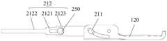
在本实用新型可选实施例中,如图4、图5和图8所示,连接环2121 上设置有断裂口2124,断裂口2124位于远离连接环2121与控制杆2122连接处的一端。In an optional embodiment of the present invention, as shown in FIG. 4 , FIG. 5 and FIG. 8 , the connecting
在该实施例中,当夹持部120和夹持芯100相对缺损创面的夹持闭合后,连接环2121远离控制杆2122连接处的一端抵在滑块211或连接轴250 上,操作者用大于预设力的拉力拽控制杆2122时,连接环2121从断裂口 2124处裂开,连接环2121与滑块211或连接片2123断开连接,将控制杆2122和连接环2121与夹持部120分离,只将外壳110、夹持部120和夹持芯100留下,避免了控制杆2122和连接环2121存在减小操作空间,影响操作人员对缺损创面的缝合,即方便操作人员对缺损创面操作。In this embodiment, after the clamping
在本实用新型可选实施例中,如图4、图5和图9所示,连接环2121 上设置有断裂区2125,断裂区2125位于远离连接环2121与控制杆2122连接处的一端,断裂区2125处的连接环2121的宽度小于连接环2121其他区域的宽度。In an optional embodiment of the present invention, as shown in FIG. 4 , FIG. 5 and FIG. 9 , the connecting
在该实施例中,当夹持部120和夹持芯100相对缺损创面的夹持闭合后,连接环2121远离的与控制杆2122连接处的一端抵在滑块211或连接轴250上,操作者用大于预设力的拉力拽控制杆2122,连接环2121从断裂区2125处断开,连接环2121与滑块211或连接片2123断开连接,将控制杆2122和连接环2121与夹持部120分离,只将外壳110、夹持部120和夹持芯100留下,避免了控制杆2122和连接环2121存在减小操作空间,影响操作人员对缺损创面的缝合,即方便操作人员对缺损创面操作。In this embodiment, after the clamping
在本实用新型可选实施例中,如图1和图2所示,内窥镜孔道缝合夹还包括:保护壳300和锁合件400。保护壳300通过锁合件400与外壳110 可拆卸连接,控制杆2122的另一端穿过锁合件400伸出保护壳300;沿控制件212的运动方向,连接环2121能够与锁合件400相干涉。In an optional embodiment of the present invention, as shown in FIG. 1 and FIG. 2 , the endoscope tunnel suture clip further includes: a
在该实施例中,当夹持部120和夹持芯100相对缺损创面的夹持闭合后,可将保护壳300与夹持组件外壳110分离,只将外壳110、夹持部120 和夹持芯100留下,避免了保护壳300存在减小操作空间,影响操作人员对缺损创面的缝合,即方便操作人员对缺损创面操作。In this embodiment, after the clamping
在本实用新型可选实施例中,如图10所示,锁合件400包括:固定环 410和多个弹性臂420。固定环410的直径小于连接环2121的直径。多个弹性臂420的一端与固定环410固定连接,并沿固定环410的周向设置,弹性臂420的另一端向弹性臂420的一侧弯折形成插脚。保护壳300上设置有多个第一连接孔310,外壳110上设置有多个与第一连接孔310相对应的第二连接孔114。锁合件400设置在保护壳300内,插脚依次插入第一连接孔310和第二连接孔114内,以使保护壳300与外壳110固定连接,控制件212的另一端穿过固定环410伸出保护壳300。In an optional embodiment of the present invention, as shown in FIG. 10 , the locking
在该实施例中,当夹持部120和夹持芯100相对缺损创面的夹持闭合后,操作者用大于预设力的拉力拽控制杆2122,连接环2121远离的与控制杆2122连接处的一端抵在滑块211或连接轴250上,连接环2121从断裂区2125或断裂口2124处断开,连接环2121与滑块211或连接片2123断开连接,将控制杆2122和连接环2121与夹持部120分离,由于固定环410 直径小于连接环2121的直径,连接环2121带动固定环410运动,固定环 410带动弹性臂420从第一连接孔310和第二连接孔114分离出来,使保护壳300、控制件212与外壳110分离,只将夹持部120、夹持芯100和外壳 110留下,避免了保护壳300存在减小操作空间,影响操作人员对缺损创面的缝合,即方便操作人员对缺损创面操作。In this embodiment, after the clamping
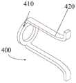
在本实用新型可选实施例中,如图11所示,锁合件400包括:连接架 430、多个弹性臂420和两个释放环440。多个弹性臂420的一端与连接架 430固定连接,弹性臂420的另一端向弹性臂420的一侧弯折形成插脚。两个释放环440分别套设在两个弹性臂420上,释放环440的直径小于连接环2121的直径。保护壳300上设置有多个第一连接孔310,外壳110上设置有多个与第一连接孔310相对应的第二连接孔114。锁合件400设置在保护壳300内,插脚依次插入第一连接孔310和第二连接孔114内,以使保护壳300与外壳110固定连接,控制件212的另一端穿过释放环440伸出保护壳300。In an optional embodiment of the present invention, as shown in FIG. 11 , the locking
在该实施例中,当夹持部120和夹持芯100相对缺损创面的夹持闭合后,操作者用大于预设力的拉力拽控制杆2122,连接环2121远离的与控制杆2122连接处的一端抵在滑块211或连接轴250上,连接环2121从断裂区2125或断裂口2124处断开,连接环2121与滑块211或连接片2123断开连接,将控制杆2122和连接环2121与夹持部120分离,由于释放环440 直径小于连接环2121的直径,连接环2121带动释放环440运动,释放环 440带动弹性臂420和连接架430从第一连接孔310和第二连接孔114分离出来,使保护壳300、控制件212与外壳110分离,只将夹持部120、夹持芯100和外壳110留下,避免了保护壳300存在减小操作空间,影响操作人员对缺损创面的缝合,即方便操作人员对缺损创面操作。In this embodiment, after the clamping
在本实用新型可选实施例中,如图12所示,保护壳300包括弹簧软管 320和固定管330。弹簧软管320与固定管330连接,固定管330上设置有第一连接孔310。由于产品的使用环境,设置弹簧软管320可以适当的弹性变形,同时也避免了其他零部件直接暴露在使用环境中,造成对产品零部件的破坏与腐蚀,从而提高产品的使用寿命,提升了产品的市场竞争力。In an optional embodiment of the present invention, as shown in FIG. 12 , the
具体说明内窥镜孔道缝合夹的工作过程:Specifically describe the working process of the endoscopic tunnel suture clip:
在操作者向前推控制件,控制件带动滑块在导向槽内滑动,使夹持部相对于外壳转动,夹持部相对于夹持芯的打开,然后向后拉控制件,使夹持部与夹持芯闭合,以对夹持缺损创面的一侧夹持,此时,操作人员据继续向后拉控制件,使控制件带动滑块滑入限位槽,滑块被限定在限位槽内,使在不需要操作者施加力的情况下,夹持部和夹持芯处于闭合锁定状态,方便操作者进行其他操作;同理,在操作者控制另一个手柄对夹持缺损创面的另一侧夹持;当需要解除该状态,只需操作人员据需要向前用力推控制件,控制件带动滑块滑出限位槽解开锁定状态。当夹持部和夹持芯处于闭合锁定状态使,操作人员据继续向后拉控制件,使连接环的前端断裂,连接环带动释放环(或固定环)运动,释放环(或固定环)带动弹性臂和连接架(或弹性臂)从第一连接孔和第二连接孔分离出来,使保护壳、控制件与外壳分离,只将夹持部、夹持芯和外壳留下。When the operator pushes the control member forward, the control member drives the slider to slide in the guide groove, so that the clamping part rotates relative to the housing, the clamping part opens relative to the clamping core, and then pulls the control member back to make the clamping part rotate relative to the casing. At this time, the operator continues to pull the control piece back, so that the control piece drives the slider to slide into the limit slot, and the slider is limited to the limit In the slot, the clamping part and the clamping core are in a closed and locked state without the need for the operator to exert force, which is convenient for the operator to perform other operations; similarly, the operator controls another handle to clamp the defect wound. The other side of the clamp is clamped; when the state needs to be released, the operator only needs to push the control piece forward as required, and the control piece drives the slider to slide out of the limit slot to release the locked state. When the clamping part and the clamping core are in a closed and locked state, the operator continues to pull the control piece back to break the front end of the connecting ring, and the connecting ring drives the release ring (or fixing ring) to move, and the releasing ring (or fixing ring) The elastic arm and the connecting frame (or the elastic arm) are driven to separate from the first connecting hole and the second connecting hole, so that the protective shell, the control part and the shell are separated, and only the clamping part, the clamping core and the shell are left.
实施例2Example 2
如图12至图14所示,本实用新型的实施例2涉及一种内窥镜孔道缝合夹,实施例2与实施例1大致相同,其主要区别在于:外壳110包括固定部112和连接管113。固定部112的一端与夹持芯100连接,两个夹持部 120分别位于固定部112的两侧,固定部112上设置有第三滑槽116,滑块 211的一端位于第三滑槽116内。连接管113与固定部112的另一端连接。第一滑槽111设置在连接管113的内壁上,控制件212的一部分位于第一滑槽111内,并可在第一滑槽111内滑动。As shown in FIGS. 12 to 14 , Embodiment 2 of the present invention relates to an endoscope tunnel suture clip. Embodiment 2 is substantially the same as Embodiment 1. The main difference is that the
在该实施例中,第三滑槽116对滑块211起到了导向及固定作用,保证了滑块211沿固定的方向的稳定运动,避免了滑块211滑脱的情况发生,从而保证了产品的使用可靠性。第一滑槽111对控制件212起到了导向及固定作用,保证了控制件212沿固定的方向的稳定运动,避免了控制件212滑脱的情况发生,从而保证了产品的使用可靠性。另外,固定部112的设置可以延长外壳110的长度,使缝合夹对跟深的地方进行操作。In this embodiment, the
实施例3Example 3
如图15至图17b所示,本实用新型的实施例3涉及一种内窥镜孔道缝合夹,实施例3与实施例1大致相同,其主要区别在于:外壳110包括固定部112连接管113和第二隔片118。固定部112的一端与夹持芯100连接,两个夹持部120分别位于固定部112的两侧,固定部112上设置有第三滑槽116,滑块211的一端位于第三滑槽116内。连接管113与固定部 112的另一端连接。第二隔片118固定在连接管113内,第二隔片118将连接管113分割为对称的两个通道,第二隔片118的两侧分别设置有第一滑槽111,两个控制件212分别位于两个通道内,控制件212的一部分位于第一滑槽111内,并可在第一滑槽111内滑动。As shown in FIG. 15 to FIG. 17 b , Embodiment 3 of the present invention relates to an endoscope tunnel suture clip. Embodiment 3 is substantially the same as Embodiment 1, and the main difference is that the
在该实施例中,连接管113被第二隔片118分割为对称的两个通道,控制件212分别位于不同的通道内,避免了两个控制件212在操作中发生干涉,即降低了控制件212发生问题的概率,从而保证了产品的使用可靠性。第一滑槽111设置在第二隔片118上,避免了第一滑槽111设置在外壳110上,导致外壳110机械强度低的情况发生,即能够保证外壳110具有机械强度。第一滑槽111对控制件212起到了导向及固定作用,保证了控制件212沿固定的方向的稳定运动,避免了控制件212滑脱的情况发生,从而保证了产品的使用可靠性。第三滑槽116对滑块211起到了导向及固定作用,第三滑槽116对滑块211起到了导向及固定作用,保证了滑块211沿固定的方向的稳定运动,避免了滑块211滑脱的情况发生,从而保证了产品的使用可靠性。In this embodiment, the connecting
实施例4Example 4
如图18至图20所示,本实用新型的实施例4涉及一种内窥镜孔道缝合夹,实施例4与实施例1大致相同,其主要区别在于:外壳110包括固定部112和连接管113。固定部112的一端与夹持芯100连接,两个夹持部120分别位于固定部112的两侧,固定部112上设置有第三滑槽116,滑块 211的一端位于第三滑槽116内。连接管113与固定部112的另一端连接。第一滑槽111为贯穿连接管113的通孔,控制件212的一部分位于第一滑槽111内,并可在第一滑槽111内滑动。As shown in FIGS. 18 to 20 , Embodiment 4 of the present invention relates to an endoscope tunnel suture clip. Embodiment 4 is substantially the same as Embodiment 1, and the main difference is that the
在该实施例中,第三滑槽116对滑块211起到了导向及固定作用,保证了滑块211沿固定的方向的稳定运动,避免了滑块211滑脱的情况发生,从而保证了产品的使用可靠性。第一滑槽111为第一通槽117,控制件 212位于第一滑槽111的部分可不小于外壳110的壁厚,从而进一步避免了控制件212滑脱的情况发生,进而进一步保证了产品的使用可靠性。可选地,控制件212位于第一滑槽111的部分等于外壳110的壁厚,避免了会划伤粘膜组织,从而提高了产品的使用安全性。In this embodiment, the
实施例5Example 5
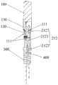
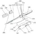
如图21至图23所示,本实用新型的实施例5涉及一种内窥镜孔道缝合夹,实施例5与实施例1大致相同,其主要区别在于:外壳110包括:As shown in FIGS. 21 to 23 , Embodiment 5 of the present invention relates to an endoscope tunnel suture clip. Embodiment 5 is substantially the same as Embodiment 1, and the main difference is that the
固定壳11和连接壳12。固定壳11的一端上设置有第二通槽13。连接壳12 设置在固定壳11的一端,连接壳12密封第二通槽13的开口,并与第二通槽13围成第一滑槽。在该实施例中,固定管330与连接壳12为同一部件。
在组装内窥镜孔道缝合夹过程中,先将控制件212位于第一滑槽111 的部分,从第二通槽13的开口处滑入第二通槽13内,再将连接壳12与固定壳11固定连接,连接壳12密封第二通槽13的开口,并与第二通槽13 围成第一滑槽111,以将控制件212位于第一滑槽111的部分锁定在第一滑槽111内,该种组装方式,简单快捷,能够提高产品的组装效率。In the process of assembling the endoscope tunnel suture clip, first slide the part of the
如图24所示,在本实用新型可选地实施例中,第一滑槽111处的外壳 110的侧壁向外壳110内凹陷形成避让空间16。As shown in Fig. 24, in an optional embodiment of the present invention, the side wall of the
在该实施例,控制件212位于第一滑槽111的凸出固定壳11部分位于避让空间16内,避免了会划伤粘膜组织,从而提高了产品的使用安全性。In this embodiment, the part of the
实施例6Example 6
如图25至图27所示,本实用新型的实施例6涉及一种内窥镜孔道缝合夹,实施例6与实施例1大致相同,其主要区别在于:外壳110还包括:壳体14和第一隔片15。壳体14上设置有第一滑槽111。第一隔片15 固定在壳体14内,第一隔片15将壳体14分割为对称的两个通道,两个控制件212分别位于两个通道内。As shown in FIGS. 25 to 27 , Embodiment 6 of the present invention relates to an endoscope tunnel suture clip. Embodiment 6 is substantially the same as Embodiment 1, and the main difference is that the
在该实施例中,壳体14被第一隔片15分割为对称的两个通道,控制件212分别位于不同的通道内,避免了两个控制件212在操作中发生干涉,即降低了控制件212发生问题的概率,从而保证了产品的使用可靠性。In this embodiment, the
如图27所示,在本实用新型的一个实施例中,第一隔片15的一端设置有转轴孔152,转轴位于转轴孔152内。第一隔片15的另一端对称地设置有插片153,壳体14上设置有与插片153相配合的插槽141。As shown in FIG. 27 , in an embodiment of the present invention, one end of the
在该实施例中,第一隔片15与壳体14插接连接,该种连接结构,连接结构、组装方便,从而能够提高产品的组装效率,进而能够提高产品的生产效率,能够降低产品的生产制造成本。In this embodiment, the
实施例7Example 7
如图28至图30所示,本实用新型的实施例7涉及一种内窥镜孔道缝合夹,实施例7与实施例6大致相同,其主要区别在于:第一隔片15的两侧分别设置有子槽151,子槽151与第一滑槽111对应设置。As shown in FIGS. 28 to 30 , Embodiment 7 of the present invention relates to an endoscope tunnel suture clip. Embodiment 7 is substantially the same as Embodiment 6, and the main difference is that the two sides of the
在该实施例中,第一滑槽111与子槽151配合使用,共同起到了导向及固定作用,限制了控制件212的滑动方向,保证了控制件212沿固定的方向的稳定运动,避免了控制件212滑脱的情况发生,从而保证了产品的使用可靠性。In this embodiment, the
显然,上述实施例仅仅是为清楚地说明所作的举例,而并非对实施方式的限定。对于所属领域的技术人员来说,在上述说明的基础上还可以做出其它不同形式的变化或变动。这里无需穷举。而由此所引伸出的显而易见的变化或变动仍处于本实用新型创造的保护范围之中。Obviously, the above-mentioned embodiments are only examples for clear description, and are not intended to limit the implementation manner. For those skilled in the art, changes or modifications in other different forms can also be made on the basis of the above description. There is no need to be exhaustive here. And the obvious changes or changes derived from this are still within the protection scope of the present invention.
在本实用新型中,术语“第一”、“第二”、“第三”仅用于描述的目的,而不能理解为指示或暗示相对重要性;术语“多个”则指两个或两个以上,除非另有明确的限定。在本实用新型中,“连接”、“固定”等术语均应做广义理解,例如,“连接”可以通过导线连接,也可以通过信号连接。对于本领域的普通技术人员而言,可以根据具体情况理解上述术语在本实用新型中的具体含义。In the present invention, the terms "first", "second" and "third" are only used for the purpose of description, and cannot be understood as indicating or implying relative importance; the term "multiple" refers to two or two more than one, unless otherwise expressly limited. In the present invention, terms such as "connection" and "fixing" should be understood in a broad sense. For example, "connection" can be connected by wires or by signals. For those of ordinary skill in the art, the specific meanings of the above terms in the present invention can be understood according to specific situations.
以上所述仅是本实用新型的具体实施方式,使本领域技术人员能够理解或实现本实用新型。对这些实施例的多种修改对本领域的技术人员来说将是显而易见的,本文中所定义的一般原理可以在不脱离本实用新型、的构思或范围的情况下,在其他实施例中实现。因此本实用新型将不会被限制于本文所示的这些实施例,而是符合与本文所公开的原理和新颖特点相一致的最宽的范围。The above are only specific embodiments of the present invention, so that those skilled in the art can understand or realize the present invention. Various modifications to these embodiments will be readily apparent to those skilled in the art, and the generic principles defined herein may be implemented in other embodiments without departing from the spirit or scope of the present invention. Accordingly, the present invention is not intended to be limited to the embodiments shown herein, but is to be accorded the widest scope consistent with the principles and novel features disclosed herein.
以上所述仅为本实用新型的优选实施例而已,并不用于限制本实用新型,对于本领域的技术人员来说,本实用新型可以有各种更改和变化。凡在本实用新型的精神和原则之内,所作的任何修改、等同替换、改进等,均应包含在本实用新型的保护范围之内。The above descriptions are only preferred embodiments of the present utility model, and are not intended to limit the present utility model. For those skilled in the art, the present utility model may have various modifications and changes. Any modification, equivalent replacement, improvement, etc. made within the spirit and principle of the present invention shall be included in the protection scope of the present invention.
Claims (20)
Applications Claiming Priority (2)
| Application Number | Priority Date | Filing Date | Title |
|---|---|---|---|
| CN201910401149 | 2019-05-15 | ||
| CN2019104011493 | 2019-05-15 |
Publications (1)
| Publication Number | Publication Date |
|---|---|
| CN211066839Utrue CN211066839U (en) | 2020-07-24 |
Family
ID=67591549
Family Applications (2)
| Application Number | Title | Priority Date | Filing Date |
|---|---|---|---|
| CN201920901776.9UActiveCN211066839U (en) | 2019-05-15 | 2019-06-14 | Endoscopic tunnel suture clip |
| CN201910517958.0AActiveCN110141295B (en) | 2019-05-15 | 2019-06-14 | Endoscopic port suture clip |
Family Applications After (1)
| Application Number | Title | Priority Date | Filing Date |
|---|---|---|---|
| CN201910517958.0AActiveCN110141295B (en) | 2019-05-15 | 2019-06-14 | Endoscopic port suture clip |
Country Status (2)
| Country | Link |
|---|---|
| CN (2) | CN211066839U (en) |
| WO (1) | WO2020228841A1 (en) |
Cited By (1)
| Publication number | Priority date | Publication date | Assignee | Title |
|---|---|---|---|---|
| CN110141295A (en)* | 2019-05-15 | 2019-08-20 | 张强 | Endoscopic channel suture clip |
Families Citing this family (6)
| Publication number | Priority date | Publication date | Assignee | Title |
|---|---|---|---|---|
| CA3156881A1 (en) | 2019-11-01 | 2021-05-06 | Doug SJOSTROM | Devices and methods for applying a hemostatic clip assembly |
| CN115103641A (en)* | 2019-11-01 | 2022-09-23 | 康美公司 | Apparatus and method for applying a hemostatic clip assembly |
| CN111202555A (en)* | 2020-03-18 | 2020-05-29 | 张强 | Endoscopic tunnel suture clip |
| CN111493980B (en)* | 2020-04-28 | 2024-12-10 | 张强 | Clamping device |
| CN118576267A (en)* | 2020-06-12 | 2024-09-03 | 南微医学科技股份有限公司 | A clamp with high grip and low release force |
| CN117653234A (en)* | 2024-01-10 | 2024-03-08 | 江苏华质医学科技有限公司 | Single-arm suture clip for endoscope duct tissue and operation method |
Family Cites Families (9)
| Publication number | Priority date | Publication date | Assignee | Title |
|---|---|---|---|---|
| JP5175833B2 (en)* | 2006-03-10 | 2013-04-03 | クック メディカル テクノロジーズ エルエルシー | Medical device capable of drawing target tissue into clip arm housing chamber |
| EP2819594A1 (en)* | 2012-02-28 | 2015-01-07 | Boston Scientific Scimed, Inc. | Omnidirectional closure clip |
| US10045781B2 (en)* | 2014-06-13 | 2018-08-14 | Ethicon Llc | Closure lockout systems for surgical instruments |
| CN107115130B (en)* | 2017-04-20 | 2020-05-19 | 南微医学科技股份有限公司 | Double-sliding-groove self-locking hemostatic clamp |
| CN107684448A (en)* | 2017-09-29 | 2018-02-13 | 苏州朗特斯医疗科技有限公司 | A kind of hemostatic clamp |
| CN108523945B (en)* | 2018-05-07 | 2024-06-25 | 张强 | Rotatable repeated opening and closing conjoined double-endoscope clamp |
| CN109350171B (en)* | 2018-11-29 | 2024-04-12 | 张强 | Conjoined double-sided clip for hemostasis and suturing through-digestive endoscope duct and operation method |
| CN211066839U (en)* | 2019-05-15 | 2020-07-24 | 张强 | Endoscopic tunnel suture clip |
| CN111202555A (en)* | 2020-03-18 | 2020-05-29 | 张强 | Endoscopic tunnel suture clip |
- 2019
- 2019-06-14CNCN201920901776.9Upatent/CN211066839U/enactiveActive
- 2019-06-14CNCN201910517958.0Apatent/CN110141295B/enactiveActive
- 2020
- 2020-06-12WOPCT/CN2020/095965patent/WO2020228841A1/ennot_activeCeased
Cited By (2)
| Publication number | Priority date | Publication date | Assignee | Title |
|---|---|---|---|---|
| CN110141295A (en)* | 2019-05-15 | 2019-08-20 | 张强 | Endoscopic channel suture clip |
| CN110141295B (en)* | 2019-05-15 | 2025-01-07 | 张强 | Endoscopic port suture clip |
Also Published As
| Publication number | Publication date |
|---|---|
| WO2020228841A1 (en) | 2020-11-19 |
| CN110141295B (en) | 2025-01-07 |
| CN110141295A (en) | 2019-08-20 |
Similar Documents
| Publication | Publication Date | Title |
|---|---|---|
| CN211066839U (en) | Endoscopic tunnel suture clip | |
| US12096942B2 (en) | Hemostasis and suturing conjoined dual-clamp capable of passing through channel of digestive endoscope and operation method | |
| JP6084347B1 (en) | Endoscopic treatment tool | |
| JP6084346B1 (en) | Clip device | |
| US12433625B2 (en) | Three-arm clamp | |
| CN104490440A (en) | Surgical operating instrument | |
| CN112137672A (en) | Tissue clamping device for endoscopic use | |
| US20240390005A1 (en) | Hemostasis clip short system | |
| WO2021184969A1 (en) | Endoscope channel suture clip | |
| CN107684445A (en) | It is a kind of to release folder cap for identical the multi-functional of clipping system of OTSC | |
| CN113939237B (en) | Tissue clamping device | |
| EP4052662A1 (en) | Multiple processing device for endoscope and use method thereof | |
| CN109674501B (en) | A connector for a disposable minimally invasive laparoscopic cutting stapler | |
| CN104434251B (en) | Nail cartridge assembly and medical stapler having same | |
| CN204379341U (en) | Nail bin groupware and there is its Medical stapler | |
| CN209269766U (en) | Staple cartridge components and medical staplers | |
| CN117940077A (en) | Clip Instruments | |
| CN210204813U (en) | Connector for disposable minimally invasive endoscopic cutting anastomat | |
| US11266412B2 (en) | Video-guided endoluminal stapling method and system | |
| EP3434199A1 (en) | Suturing device | |
| CN209529237U (en) | Nail anvil shaft and circular-pipe anastomat | |
| CN208625786U (en) | A multifunctional clip release cap for OTSC anastomotic clip system | |
| CN106923912A (en) | Tubular tissue closing device | |
| JP6755498B2 (en) | Suture device | |
| CN117679102B (en) | Split type anastomotic clamp |
Legal Events
| Date | Code | Title | Description |
|---|---|---|---|
| GR01 | Patent grant | ||
| GR01 | Patent grant |