CN211065057U - Heater and aerosol generating device including the same - Google Patents
Heater and aerosol generating device including the sameDownload PDFInfo
- Publication number
- CN211065057U CN211065057UCN201921480758.4UCN201921480758UCN211065057UCN 211065057 UCN211065057 UCN 211065057UCN 201921480758 UCN201921480758 UCN 201921480758UCN 211065057 UCN211065057 UCN 211065057U
- Authority
- CN
- China
- Prior art keywords
- heater
- resistance element
- base body
- electrode lead
- spiral groove
- Prior art date
- Legal status (The legal status is an assumption and is not a legal conclusion. Google has not performed a legal analysis and makes no representation as to the accuracy of the status listed.)
- Active
Links
Images


Landscapes
- Resistance Heating (AREA)
Abstract
Description
Translated fromChinese技术领域technical field
本申请涉及烟具领域,尤其涉及一种加热器以及包含该加热器的气溶胶生成装置。The present application relates to the field of smoking articles, and in particular, to a heater and an aerosol generating device including the heater.
背景技术Background technique
低温烘烤烟具的一般包括加热器,加热器通电后产生热量,烘烤容置于低温烘烤烟具内的烟支,从而产生用户可直接抽吸的烟雾。由于低温烘烤烟具便携性好,不会产生明火,且环保的特点,受到很多吸烟人士的青睐。The low-temperature curing smoking device generally includes a heater, which generates heat after being energized, and bakes the cigarettes accommodated in the low-temperature curing smoking device, thereby generating smoke that the user can directly inhale. Because of its good portability, no open flame, and environmental protection features, low-temperature curing tobacco sets are favored by many smokers.
现有的低温烘烤烟具的加热方式通常采用中心加热式和外围加热式。中心加热式为加热器插入烟支内部,外围加热式为筒状加热器包裹烟支,通过加热器与烟支直接接触,从而将加热器上产生的热量传导至发热物质上,从而实现对烟支的烘烤。The heating methods of the existing low-temperature curing smoking tools usually adopt the central heating type and the peripheral heating type. The central heating type is that the heater is inserted into the inside of the cigarette, and the peripheral heating type is that the cylindrical heater wraps the cigarette. Baking of sticks.
中心加热式较为常见的是在陶瓷基体上印刷多个导电轨迹(或者发热电路)作为加热器,该加热器存在的问题是:升温速率慢,通常需要10秒以上才能升温到220°以上;电阻温度系数小,温控存在滞后现象;加热温度分布不均匀。The central heating type is more common to print multiple conductive traces (or heating circuits) on the ceramic substrate as heaters. The problems with this heater are: the heating rate is slow, and it usually takes more than 10 seconds to heat up to 220° or more; resistance; The temperature coefficient is small, and the temperature control has a hysteresis phenomenon; the heating temperature distribution is uneven.
实用新型内容Utility model content
本申请提供一种加热器以及包含该加热器的气溶胶生成装置,旨在解决现有加热器存在的升温速率慢的问题。The present application provides a heater and an aerosol generating device including the heater, aiming at solving the problem of slow heating rate existing in the existing heater.
基于以上目的,本申请第一方面提供了一种加热器,所述加热器包括:Based on the above purpose, a first aspect of the present application provides a heater, the heater comprising:
基体,具有沿所述基体的轴向方向延伸的通孔;a base body having through holes extending in the axial direction of the base body;
限位部件,位于所述基体的一端且与所述基体固定连接;a limiting component, located at one end of the base body and fixedly connected with the base body;
电阻元件,包括至少部分收容于所述通孔内的第一部分电阻元件、以及沿所述基体的周向方向缠绕在所述基体的外壁上的第二部分电阻元件。The resistance element includes a first partial resistance element at least partially accommodated in the through hole, and a second partial resistance element wound on the outer wall of the base body along the circumferential direction of the base body.
在一种实施方式中,所述基体的外壁上具有螺旋槽;所述第二部分电阻元件收容于所述螺旋槽。In one embodiment, the outer wall of the base body has a spiral groove; the second partial resistance element is accommodated in the spiral groove.
在一种实施方式中,所述基体远离所述限位部件的一端设有连通所述通孔和所述螺旋槽的第一开槽;In one embodiment, one end of the base body away from the limiting member is provided with a first slot that communicates with the through hole and the helical groove;
所述电阻元件还包括与所述第一部分电阻元件和所述第二部分电阻元件连接的第三部分电阻元件,所述第三部分电阻元件收容于所述第一开槽。The resistance element further includes a third partial resistance element connected to the first partial resistance element and the second partial resistance element, and the third partial resistance element is accommodated in the first slot.
在一种实施方式中,所述第二部分电阻元件通过胶粘材料粘接在所述螺旋槽上;和/或,In one embodiment, the second partial resistance element is adhered to the spiral groove by an adhesive material; and/or,
所述基体外壁上覆盖有封釉层,以将所述第二部分电阻元件封装在所述螺旋槽内。The outer wall of the base is covered with a sealing glaze layer to encapsulate the second partial resistance element in the spiral groove.
在一种实施方式中,所述限位部件与所述基体一体成型,所述限位部件设有与所述螺旋槽连通的第二开槽。In one embodiment, the limiting member is integrally formed with the base body, and the limiting member is provided with a second slot that communicates with the spiral groove.
在一种实施方式中,所述限位部件套接在所述基体上,所述基体位于所述限位部件的一端设有与所述螺旋槽连通的第三开槽。In one embodiment, the limiting member is sleeved on the base body, and one end of the base body located at the limiting member is provided with a third slot that communicates with the helical groove.
在一种实施方式中,所述加热器还包括第一电极引线和第二电极引线;In one embodiment, the heater further includes a first electrode lead and a second electrode lead;
所述第一电极引线与所述第一部分电阻元件连接,所述第二电极引线与所述第二部分电阻元件连接。The first electrode lead is connected to the first partial resistance element, and the second electrode lead is connected to the second partial resistance element.
在一种实施方式中,所述第一电极引线的至少一部分穿越所述限位部件与所述第一部分电阻元件连接;和/或,In one embodiment, at least a part of the first electrode lead is connected to the first partial resistance element through the limiting member; and/or,
所述第二电极引线的至少一部分穿越所述限位部件与所述第二部分电阻元件连接。At least a part of the second electrode lead is connected to the second partial resistance element through the limiting member.
在一种实施方式中,所述基体由陶瓷、复合材料、聚合物材料、涂覆或包裹绝缘层的金属、经过阳极氧化且表面绝缘的金属材料中至少之一制成。In one embodiment, the substrate is made of at least one of ceramics, composite materials, polymer materials, metals coated or wrapped with insulating layers, and anodized and surface-insulated metal materials.
基于以上目的,本申请第二方面提供了一种气溶胶生成装置,所述气溶胶生成装置包括上述的加热器、以及用于为所述加热器供电的电源组件。Based on the above objective, a second aspect of the present application provides an aerosol generating device, the aerosol generating device comprising the above-mentioned heater and a power supply assembly for supplying power to the heater.
本申请提供的加热器以及包含该加热器的气溶胶生成装置,电阻元件一部分穿过基体的通孔,另一部分沿基体的周向方向缠绕在基体的外壁上;解决了现有加热器存在的升温速率慢的问题;升温速率快,加热效果好,提升了用户体验。In the heater and the aerosol generating device including the heater provided by the present application, a part of the resistance element passes through the through hole of the base body, and the other part is wound on the outer wall of the base body along the circumferential direction of the base body; it solves the problem of existing heaters. The problem of slow heating rate; the heating rate is fast, the heating effect is good, and the user experience is improved.
附图说明Description of drawings
一个或多个实施例通过与之对应的附图中的图片进行示例性说明,这些示例性说明并不构成对实施例的限定,附图中具有相同参考数字标号的元件表示为类似的元件,除非有特别申明,附图中的图不构成比例限制。One or more embodiments are exemplified by the pictures in the corresponding drawings, and these exemplifications do not constitute limitations of the embodiments, and elements with the same reference numerals in the drawings are denoted as similar elements, Unless otherwise stated, the figures in the accompanying drawings do not constitute a scale limitation.
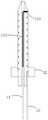
图1是本申请实施方式一提供的加热器结构示意图;1 is a schematic structural diagram of a heater provided by Embodiment 1 of the present application;
图2是本申请实施方式一提供的加热器中基体结构示意图;2 is a schematic diagram of the structure of the substrate in the heater provided in Embodiment 1 of the present application;
图3是本申请实施方式一提供的加热器中限位部件结构示意图;3 is a schematic structural diagram of a limiting member in a heater provided in Embodiment 1 of the present application;
图4是本申请实施方式一提供的加热器沿A-A线方向的剖面结构示意图;4 is a schematic cross-sectional structure diagram of the heater provided in Embodiment 1 of the present application along the line A-A;
图5是本申请实施方式一提供的加热器沿A-A线方向的另一剖面结构示意图;5 is another schematic cross-sectional structure diagram of the heater provided in Embodiment 1 of the present application along the A-A line direction;
图6是本申请实施方式二提供的加热器结构示意图;6 is a schematic structural diagram of a heater provided by Embodiment 2 of the present application;
图7是本申请实施方式三提供的气溶胶生成装置结构示意图。FIG. 7 is a schematic structural diagram of an aerosol generating device according to Embodiment 3 of the present application.
具体实施方式Detailed ways
为了便于理解本申请,下面结合附图和具体实施方式,对本申请进行更详细的说明。需要说明的是,当元件被表述“固定于”另一个元件,它可以直接在另一个元件上、或者其间可以存在一个或多个居中的元件。当一个元件被表述“连接”另一个元件,它可以是直接连接到另一个元件、或者其间可以存在一个或多个居中的元件。本说明书所使用的术语“上”、“下”、“左”、“右”、“内”、“外”以及类似的表述只是为了说明的目的。In order to facilitate the understanding of the present application, the present application will be described in more detail below with reference to the accompanying drawings and specific embodiments. It should be noted that when an element is referred to as being "fixed to" another element, it can be directly on the other element, or one or more intervening elements may be present therebetween. When an element is referred to as being "connected" to another element, it can be directly connected to the other element or one or more intervening elements may be present therebetween. The terms "upper", "lower", "left", "right", "inner", "outer" and similar expressions used in this specification are for illustrative purposes only.
除非另有定义,本说明书所使用的所有的技术和科学术语与属于本申请的技术领域的技术人员通常理解的含义相同。本说明书中在本申请的说明书中所使用的术语只是为了描述具体的实施方式的目的,不是用于限制本申请。本说明书所使用的术语“和/或”包括一个或多个相关的所列项目的任意的和所有的组合。Unless otherwise defined, all technical and scientific terms used in this specification have the same meaning as commonly understood by one of ordinary skill in the technical field belonging to this application. The terms used in the specification of the present application in this specification are only for the purpose of describing specific embodiments, and are not used to limit the present application. As used in this specification, the term "and/or" includes any and all combinations of one or more of the associated listed items.
实施方式一Embodiment 1
如图1-图4所示,为本申请实施方式一所提供的一种加热器10,所述加热器10包括基体11、限位部件12、电阻元件(图中的131、132、133所示)、第一电极引线14以及第二电极引线15。As shown in FIG. 1-FIG. 4, a
基体11,具有沿基体11的轴向方向延伸(图中的虚线箭头所示)的通孔111;基体11的外壁上具有螺旋槽112。基体11远离限位部件12的一端设有连通通孔111和螺旋槽112的开槽113。The
在本实施例中,基体11的形状大致呈圆柱状,基体11的一端呈锥状,便于加热器10与烟支间的插拔,减少加热器10与与烟支间的阻力。呈圆柱状的基体11的轴向方向可以为圆柱的中心轴方向、或者与中心轴平行或者大致平行的方向。通孔111贯穿呈圆柱状的基体11的上、下两个面,或者其中的至少一个面。In this embodiment, the shape of the
在其他实施方式中,基体11的截面形状也可以为方形状、多边形或其它异形形状等等,也是可以实现的。例如截面为方形状的基体11呈长条形片状,其轴向方向一般指的是其长度方向或者与长度方向平行或者大致平行的方向。In other embodiments, the cross-sectional shape of the
基体11可由陶瓷、复合材料、聚合物材料、涂覆或包裹绝缘层的金属、经过阳极氧化且表面绝缘的金属材料中至少之一制成。在本实施例中,选用了陶瓷作为基体11的制作材料。The
在本实施例中,通孔111用于收容第一部分电阻元件132(图4中的灰色部分所示),螺旋槽112用于收容第二部分电阻元件131,开槽113用于收容第三部分电阻元件133(图4中的黑色部分所示),第三部分电阻元件133的两端分别与第一部分电阻元件132和第二部分电阻元件131连接。In this embodiment, the
在本实施例中,通过设置在基体11的外壁上的第二部分电阻元件131,可确保加热器10上、下的加热温度分布较为均匀。进一步地,通过合理地设置螺旋槽112的螺距,可调整加热器10上、下的加热温度分布状况。螺距的具体设置在此不作限定,可以等距的进行设置,也可非等距的进行设置。In this embodiment, the second
需要说明的是,第一部分电阻元件132、第二部分电阻元件131以及第三部分电阻元件133可以是同一根电阻元件的不同部分,例如:第三部分电阻元件133为一根电阻元件弯曲后的折弯部分,第一部分电阻元件132和第二部分电阻元件131分别为一根电阻元件弯曲后的非折弯部分。It should be noted that the first
或者,第一部分电阻元件132、第二部分电阻元件131以及第三部分电阻元件133是多根电阻元件,例如:两根电阻元件、三根电阻元件、或者三根以上电阻元件等等。Alternatively, the first partial
还需要说明的是,开槽113的大小、形状、长短等等在此不做限定。可以理解的,在其他实施方式中,不设置开槽113也是可以实现的。It should also be noted that the size, shape, length, etc. of the
在本实施例中,电阻元件可包括电热丝、带状的发热片、带状的发热网、发热管、螺旋发热线圈等中的至少一种,优选采用具有合适线径的电热丝。In this embodiment, the resistance element may include at least one of a heating wire, a belt-shaped heating sheet, a belt-shaped heating net, a heating tube, a spiral heating coil, etc., preferably a heating wire with a suitable wire diameter is used.
在本实施例中,电阻元件可由具有电阻温度系数或电阻率温度系数特性的发热材料制成,发热材料可以是金属材料、合金材料或由陶瓷材料和金属材料制成的复合材料等,例如导电陶瓷。例如合适的金属材料的示例可以包括钛、镍、铂、锆或铜等,例如合适的合金材料的示例可以包括不锈钢、镍合金、铬合金、锆合金、钛合金、钨合金、镍铬合金、镍铁合金、铁铝合金、铁铬铝合金或铁锰铝合金等等。本实施例中优选通过采用具有较高电阻温度系数或电阻率温度系数的发热材料制成的电阻元件,例如优选采用金属镍、铂、铜或者铁铝合金、铁铬铝合金等,一方面用于在电流通过时发热给烟丝进行加热,另一方面可以通过本身阻值随温度的变化监控加热器的加热温度,结合控制电路一起对加热器的加热温度进行实时控制,从而使加热温度维持在一定水平或特定范围内,保持抽吸的口感并抑制烟丝中有害物质的释放。In this embodiment, the resistance element may be made of a heat-generating material with a temperature coefficient of resistance or a temperature coefficient of resistivity, and the heat-generating material may be a metal material, an alloy material, or a composite material made of a ceramic material and a metal material, etc., such as conductive ceramics. Examples of suitable metal materials may include titanium, nickel, platinum, zirconium, or copper, for example, and examples of suitable alloy materials may include stainless steel, nickel alloys, chromium alloys, zirconium alloys, titanium alloys, tungsten alloys, nichromes, Nickel-iron alloy, iron-aluminum alloy, iron-chromium-aluminum alloy or iron-manganese-aluminum alloy, etc. In this embodiment, it is preferable to use a resistance element made of a heating material with a higher temperature coefficient of resistance or a temperature coefficient of resistivity, for example, metal nickel, platinum, copper or iron-aluminum alloy, iron-chromium-aluminum alloy, etc. are preferably used. When the current passes through, it generates heat to heat the shredded tobacco. On the other hand, the heating temperature of the heater can be monitored through the change of its resistance value with the temperature, and the heating temperature of the heater can be controlled in real time in combination with the control circuit, so that the heating temperature can be maintained at Within a certain level or a specific range, the taste of smoking is maintained and the release of harmful substances in the cut tobacco is inhibited.
在本实施例中,第一电极引线14与第一部分电阻元件132连接,第二电极引线15与第二部分电阻元件131连接。In this embodiment, the
第一电极引线14与第二电极引线15是相互绝缘的,第一电极引线14与第二电极引线15可分别与电源和/或温度测试系统的正负极电连接。The
请参考图5所示,在其他实施方式中,为了降低限位部件12的温度,第一电极引线14的至少一部分穿越限位部件12与第一部分电阻元件132连接,第二电极引线15的至少一部分穿越限位部件12与第二部分电阻元件131连接。Referring to FIG. 5 , in other embodiments, in order to reduce the temperature of the limiting
在本实施例中,第二部分电阻元件131沿基体11的周向方向缠绕在基体11的外壁上的螺旋槽112之后,可以覆盖封釉层使第二部分电阻元件131与基体11固定在一起。封釉层一方面可以填充第二部分电阻元件131与螺旋槽112之间的间隙,减少烟丝加热过程中的积碳;另一方面封釉层表面光滑,可以减少加热器与烟支之间的摩擦力,便于插拔和积碳清除。In this embodiment, after the second
在其他实施方式中,第二部分电阻元件131可通过胶粘材料粘接在螺旋槽112上,胶粘材料可以为AB胶或者其他类似的材料。In other embodiments, the second
请结合图2-图3进行理解,限位部件12位于基体11的一端且与基体固定11连接,限位部件12一方面用于烟支的限位,另一方面在加热器10与其他结构件进行装配时便于安装。Please understand with reference to FIGS. 2 to 3 , the limiting
在本实施例中,限位部件12套接在基体11上。具体地,限位部件12包括限位部件本体121和通孔122,通孔122的直径大于或等于基体11的直径。In this embodiment, the limiting
需要说明的是,限位部件12的形状在此不作限定,可以大致呈圆柱形、方形等等。It should be noted that the shape of the limiting
在本实施例中,基体11位于限位部件12的一端设有与螺旋槽112连通的开槽114。开槽114便于第二部分电阻元件131和/或第二电极引线15的部分隐藏在加热器结构中,既整洁美观,又可以减少装配体积。In this embodiment, an end of the
需要说明的是,图1-图4都是基于基体11的外壁上具有螺旋槽112进行阐述或者说明。可以理解的,基体11的外壁上不设置螺旋槽112,即第二部分电阻元件131直接沿基体11的周向方向缠绕在基体11的外壁上,也是可以实现的。It should be noted that, FIGS. 1 to 4 are all described or described based on the fact that the outer wall of the
以下结合图1-图4对加热器的装配过程进行说明:The assembly process of the heater is described below with reference to Figures 1 to 4:
如图1和图2所示,首先将一根电阻元件的一端从基体11的通孔111穿出,将电阻元件的另一端通过开槽113折弯之后,沿着螺旋槽112缠绕在基体11的外壁上,缠绕之后的电阻元件部分嵌入开槽114中。As shown in FIG. 1 and FIG. 2 , first, one end of a resistive element is passed through the through
接着,将如图3所示的限位部件12套接在基体11上,即开槽114的部分。Next, the limiting
最后,对加热器进行封釉,通过覆盖封釉层一方面可以填充电阻元件与螺旋槽之间的间隙,减少烟丝加热过程中的积碳;另一方面封釉层表面光滑,可以减少加热器与烟支之间的摩擦力,便于插拔和积碳清除。Finally, the heater is sealed with glaze. On the one hand, the gap between the resistance element and the spiral groove can be filled by covering the sealing glaze layer to reduce carbon deposition during the heating process of the cut tobacco; on the other hand, the surface of the sealing glaze layer is smooth, which can reduce the heater The friction between the cigarette and the cigarette is easy to insert and remove and remove carbon deposits.
实施方式二Embodiment 2
图6是本申请实施方式二提供的加热器结构示意图,在以下描述中为了简洁起见,在这里将不全部重复与图1-图4中相同或类似的部件或特征的描述。应当理解,以上关于图1-图4的示例描述的布置和另选方案等也适用于图6的示例。FIG. 6 is a schematic structural diagram of the heater provided in Embodiment 2 of the present application. For the sake of brevity, the descriptions of the same or similar components or features as those in FIGS. 1 to 4 will not be repeated here. It should be understood that the arrangements, alternatives, etc. described above with respect to the examples of FIGS. 1-4 also apply to the example of FIG. 6 .
如图6所示,加热器20包括基体21、限位部件22、电阻元件(图中未示出)、第一电极引线(图中未示出)以及第二电极引线(图中未示出)。基体21包括通孔211、螺旋槽212,连通通孔211和螺旋槽212的开槽213。As shown in FIG. 6, the
与实施方式一不同的是,实施方式二的限位部件22与基体21是一体成型,便于在基体21成型过程中减少开模次数,节约成本。Different from the first embodiment, the limiting
限位部件22上还设有与螺旋槽212连通的开槽221,开槽221便于第二部分电阻元件和/或第二电极引线的部分隐藏在加热器结构中,既整洁美观,又可以减少装配体积。The limiting
实施方式三Embodiment 3
图7是本申请实施方式三提供的一种气溶胶生成装置,所述气溶胶生成装置包括加热器100、以及用于为所述加热器供电的电源组件200。FIG. 7 is an aerosol generating device according to Embodiment 3 of the present application. The aerosol generating device includes a
其中加热器100与前述实施方式相同,在此不做赘述。The
所述电源组件200用于给所述加热器提供电能,从而使得所述加热器导电产生热量,从而加热烟支。The power supply assembly 200 is used for providing electrical power to the heater, so that the heater conducts electricity to generate heat, thereby heating the cigarette.
以下对气溶胶生成装置的工作原理进行大致的说明:The working principle of the aerosol generating device is briefly described below:
当烟支放入到加热腔(图中100所示的区域)中时,加热器100的(限位部件以上的)基体部分可插入到烟支内的烟草中。When the cigarette is placed into the heating chamber (the area shown at 100 in the figure), the base portion of the heater 100 (above the limiting member) can be inserted into the tobacco in the cigarette.
在电源组件200给加热器100进行供电之后,加热器100的电阻元件开始发热并对烟草进行加热。加热到一定程度之后,用户可进行抽吸。After the power supply assembly 200 supplies power to the
在电源组件200停止给加热器100供电,加热器100的电阻元件开始逐渐降温。When the power supply assembly 200 stops supplying power to the
需要说明的是,本申请的说明书及其附图中给出了本申请的较佳的实施例,但是,本申请可以通过许多不同的形式来实现,并不限于本说明书所描述的实施例,这些实施例不作为对本申请内容的额外限制,提供这些实施例的目的是使对本申请的公开内容的理解更加透彻全面。并且,上述各技术特征继续相互组合,形成未在上面列举的各种实施例,均视为本申请说明书记载的范围;进一步地,对本领域普通技术人员来说,可以根据上述说明加以改进或变换,而所有这些改进和变换都应属于本申请所附权利要求的保护范围。It should be noted that preferred embodiments of the present application are given in the description of the present application and the accompanying drawings. However, the present application can be implemented in many different forms, and is not limited to the embodiments described in the present specification. These embodiments are not intended as additional limitations to the content of the present application, and are provided for the purpose of making the understanding of the disclosure of the present application more thorough and complete. In addition, the above technical features continue to be combined with each other to form various embodiments not listed above, which are all regarded as the scope of the description of this application; further, for those of ordinary skill in the art, they can be improved or transformed according to the above descriptions , and all these improvements and transformations should belong to the protection scope of the appended claims of this application.
Claims (10)
Priority Applications (1)
| Application Number | Priority Date | Filing Date | Title |
|---|---|---|---|
| CN201921480758.4UCN211065057U (en) | 2019-09-06 | 2019-09-06 | Heater and aerosol generating device including the same |
Applications Claiming Priority (1)
| Application Number | Priority Date | Filing Date | Title |
|---|---|---|---|
| CN201921480758.4UCN211065057U (en) | 2019-09-06 | 2019-09-06 | Heater and aerosol generating device including the same |
Publications (1)
| Publication Number | Publication Date |
|---|---|
| CN211065057Utrue CN211065057U (en) | 2020-07-24 |
Family
ID=71632924
Family Applications (1)
| Application Number | Title | Priority Date | Filing Date |
|---|---|---|---|
| CN201921480758.4UActiveCN211065057U (en) | 2019-09-06 | 2019-09-06 | Heater and aerosol generating device including the same |
Country Status (1)
| Country | Link |
|---|---|
| CN (1) | CN211065057U (en) |
Cited By (8)
| Publication number | Priority date | Publication date | Assignee | Title |
|---|---|---|---|---|
| CN112425821A (en)* | 2020-11-27 | 2021-03-02 | 上海烟草集团有限责任公司 | Heater and smoking set |
| CN113455715A (en)* | 2021-07-05 | 2021-10-01 | 深圳麦时科技有限公司 | Aerosol generating device and heating assembly thereof |
| CN114223963A (en)* | 2021-12-24 | 2022-03-25 | 重庆江陶科技有限公司 | Resistive heater and aerosol generating device for aerosol generating device |
| CN114468363A (en)* | 2020-11-11 | 2022-05-13 | 湖南中烟工业有限责任公司 | Heating and baking low-temperature smoking set |
| CN114468362A (en)* | 2020-11-11 | 2022-05-13 | 湖南中烟工业有限责任公司 | Low-temperature heating cigarette appliance and heating body thereof |
| CN114587023A (en)* | 2022-03-09 | 2022-06-07 | 海南摩尔兄弟科技有限公司 | Aerosol forming device and heating assembly thereof |
| WO2023284802A1 (en)* | 2021-07-14 | 2023-01-19 | 深圳市合元科技有限公司 | Heating device for aerosol generation apparatus and aerosol generation apparatus |
| EP4434363A4 (en)* | 2021-12-21 | 2025-03-19 | Shenzhen First Union Technology Co., Ltd. | AEROSOL GENERATING DEVICE AND ASSOCIATED HEATING DEVICE |
- 2019
- 2019-09-06CNCN201921480758.4Upatent/CN211065057U/enactiveActive
Cited By (8)
| Publication number | Priority date | Publication date | Assignee | Title |
|---|---|---|---|---|
| CN114468363A (en)* | 2020-11-11 | 2022-05-13 | 湖南中烟工业有限责任公司 | Heating and baking low-temperature smoking set |
| CN114468362A (en)* | 2020-11-11 | 2022-05-13 | 湖南中烟工业有限责任公司 | Low-temperature heating cigarette appliance and heating body thereof |
| CN112425821A (en)* | 2020-11-27 | 2021-03-02 | 上海烟草集团有限责任公司 | Heater and smoking set |
| CN113455715A (en)* | 2021-07-05 | 2021-10-01 | 深圳麦时科技有限公司 | Aerosol generating device and heating assembly thereof |
| WO2023284802A1 (en)* | 2021-07-14 | 2023-01-19 | 深圳市合元科技有限公司 | Heating device for aerosol generation apparatus and aerosol generation apparatus |
| EP4434363A4 (en)* | 2021-12-21 | 2025-03-19 | Shenzhen First Union Technology Co., Ltd. | AEROSOL GENERATING DEVICE AND ASSOCIATED HEATING DEVICE |
| CN114223963A (en)* | 2021-12-24 | 2022-03-25 | 重庆江陶科技有限公司 | Resistive heater and aerosol generating device for aerosol generating device |
| CN114587023A (en)* | 2022-03-09 | 2022-06-07 | 海南摩尔兄弟科技有限公司 | Aerosol forming device and heating assembly thereof |
Similar Documents
| Publication | Publication Date | Title |
|---|---|---|
| CN211065057U (en) | Heater and aerosol generating device including the same | |
| US11432592B2 (en) | Method of forming heating elements that are coupled together to a voltage source | |
| JP2023105272A (en) | Aerosol generator with fixed heater | |
| CA2062539C (en) | Flavor generating article | |
| US5249586A (en) | Electrical smoking | |
| JP2021072836A (en) | Long heater assembly for aerosol generation system and heating assembly | |
| CN109674095B (en) | Cigarette heaters and electric heating smoking devices, thermal insulation devices | |
| CN210611028U (en) | Heating body and electric heating smoking device | |
| CN214386095U (en) | Heater for aerosol generating device and aerosol generating device | |
| CN112205682A (en) | Carbon nanofiber membrane rapid heating electronic cigarette heating pipe | |
| WO2022206428A1 (en) | Aerosol generating device and resistance heater for aerosol generating device | |
| WO2021104471A1 (en) | Heater, and cigarette utensil containing same | |
| CN219781579U (en) | Heaters and aerosol generating devices | |
| CN219182820U (en) | Heating element and aerosol generating device | |
| WO2023109532A1 (en) | Heater and cigarette utensil comprising same | |
| CN213939716U (en) | Carbon nanofiber membrane rapid heating electronic cigarette heating pipe | |
| CN220441923U (en) | Heating components and aerosol generating devices | |
| CN219353085U (en) | Heating element and aerosol generating device | |
| WO2023131185A1 (en) | Aerosol generating device and resistive heater for aerosol generating device | |
| CN217609592U (en) | Gas mist generating device and heater for gas mist generating device | |
| CN218073474U (en) | Heating module and aerosol generating device | |
| CN219353071U (en) | Heating element and aerosol generating device | |
| CN219373827U (en) | Aerosol generating device and heating structure thereof | |
| CN217826773U (en) | Gas mist generating device and heater for gas mist generating device | |
| CN211153803U (en) | Spiral heating element |
Legal Events
| Date | Code | Title | Description |
|---|---|---|---|
| GR01 | Patent grant | ||
| GR01 | Patent grant |