CN211060850U - Depth detection system and its bracket and electronics - Google Patents
Depth detection system and its bracket and electronicsDownload PDFInfo
- Publication number
- CN211060850U CN211060850UCN201921543846.4UCN201921543846UCN211060850UCN 211060850 UCN211060850 UCN 211060850UCN 201921543846 UCN201921543846 UCN 201921543846UCN 211060850 UCN211060850 UCN 211060850U
- Authority
- CN
- China
- Prior art keywords
- receiving module
- light
- edge
- detection system
- detection
- Prior art date
- Legal status (The legal status is an assumption and is not a legal conclusion. Google has not performed a legal analysis and makes no representation as to the accuracy of the status listed.)
- Active
Links
Images


Landscapes
- Length Measuring Devices By Optical Means (AREA)
Abstract
Translated fromChinese
Description
Translated fromChinese技术领域technical field
本实用新型涉及光电技术领域,尤其涉及一种深度检测系统及其支架和电子装置。The utility model relates to the field of optoelectronic technology, in particular to a depth detection system, a bracket and an electronic device thereof.
背景技术Background technique
随着技术进步和人们生活水平提高,对于手机、平板电脑、相机等电子产品,用户要求具有更多功能和时尚外观。目前,手机的发展趋势是轻薄、接近全面屏,同时具有前置摄像头或人脸识别等功能。传统的人脸识别技术是基于二维的图像比对,很容易被照片破解。因此,具有更加安全的三维(Three-dimensional,3D)人脸识别技术以及基于此的各种3D生物特征检测和识别是未来电子产品的发展趋势。结构光(structured light)是指具有特定图案的光束,其可被设计成条纹图案、规则点阵图案、网格图案、散斑图案、编码图案等,甚至更复杂图案的光场。目前结构光被广泛应用在深度检测系统中,用于实现三维的图像绘制或生物特征检测,比如身份识别、投影仪、三维轮廓重现、深度测量、防伪辨识等。然而,现有技术的深度检测用于手机等便携式的电子装置时,能够精确测量的深度范围较小。With the advancement of technology and the improvement of people's living standards, users require more functions and stylish appearance for electronic products such as mobile phones, tablet computers, and cameras. At present, the development trend of mobile phones is to be thin and light, close to full screen, and have functions such as front camera or face recognition. Traditional face recognition technology is based on two-dimensional image comparison, which can be easily cracked by photos. Therefore, it is the development trend of future electronic products to have a more secure three-dimensional (Three-dimensional, 3D) face recognition technology and various 3D biometric detection and recognition based thereon. Structured light refers to a light beam with a specific pattern, which can be designed into a striped pattern, a regular lattice pattern, a grid pattern, a speckle pattern, a coding pattern, etc., or even a light field of more complex patterns. At present, structured light is widely used in depth detection systems to achieve three-dimensional image rendering or biometric detection, such as identity recognition, projectors, three-dimensional contour reproduction, depth measurement, and anti-counterfeiting identification. However, when depth detection in the prior art is used in portable electronic devices such as mobile phones, the depth range that can be accurately measured is small.
实用新型内容Utility model content
有鉴于此,本实用新型提供一种用于解决现有技术问题的深度检测系统、支架和电子装置。In view of this, the present invention provides a depth detection system, a bracket and an electronic device for solving the problems of the prior art.
本实用新型的一个方面公开了一种深度检测系统,发射模组,用于发射具有参考图案的检测光束;接收模组,用于采集被外部对象反射的具有检测图案的检测光束;其中,所述接收模组的边缘所在直线与所述发射模组和接收模组之间的基线具有锐角的夹角。One aspect of the present utility model discloses a depth detection system. A transmitting module is used for transmitting a detection beam with a reference pattern; a receiving module is used for collecting a detection beam with a detection pattern reflected by an external object; The straight line where the edge of the receiving module is located and the baseline between the transmitting module and the receiving module have an acute included angle.
可选的,所述接收模组具有面向外部投影空间的感光面,所述感光面的边缘与所述基线具有锐角的夹角。Optionally, the receiving module has a photosensitive surface facing the external projection space, and an edge of the photosensitive surface and the base line have an acute included angle.
可选的,所述接收模组的感光面的边缘所在直线或其平行线相对所述基线所在直线具有大于0度且小于或等于45度的夹角,或者述接收模组的感光面的边缘所在直线或其平行线相对所述基线所在直线具有大于0度且小于或等于15度的夹角。Optionally, the line where the edge of the photosensitive surface of the receiving module is located or its parallel line has an included angle greater than 0 degrees and less than or equal to 45 degrees relative to the line where the base line is located, or the edge of the photosensitive surface of the receiving module The straight line or its parallel line has an included angle greater than 0 degrees and less than or equal to 15 degrees relative to the straight line on which the base line is located.
可选的,所述发射模组具有发光面,所述发射模组的发光面的边缘所在直线和所述接收模组的感光面边缘所在直线之间夹角为大于0度且小于或等于45度,或所述发射模组的发光面边缘所在直线和所述接收模组的感光面边缘所在直线之间夹角为大于0度且小于或等于15度。Optionally, the transmitting module has a light-emitting surface, and the included angle between the straight line where the edge of the light-emitting surface of the transmitting module is located and the straight line where the edge of the photosensitive surface of the receiving module is located is greater than 0 degrees and less than or equal to 45 degrees. degrees, or the included angle between the line where the edge of the light-emitting surface of the transmitting module is located and the line where the edge of the light-emitting surface of the receiving module is located is greater than 0 degrees and less than or equal to 15 degrees.
可选的,所述接收模组具有和所述感光面垂直的感光轴,所述夹角是将所述接收模组基于感光轴旋转一定角度形成。Optionally, the receiving module has a photosensitive axis perpendicular to the photosensitive surface, and the included angle is formed by rotating the receiving module by a certain angle based on the photosensitive axis.
可选的,所述感光面为矩形,所述接收模组包括图像传感器,所述感光面为图像传感器的感光区域。Optionally, the photosensitive surface is rectangular, the receiving module includes an image sensor, and the photosensitive surface is a photosensitive area of the image sensor.
可选的,所述参考图案包括多个相同的矩形的子参考图案,所述子参考图案的检测长度大于所述子参考图案的宽度。Optionally, the reference pattern includes a plurality of identical rectangular sub-reference patterns, and the detection length of the sub-reference patterns is greater than the width of the sub-reference patterns.
本实用新型的一个方面公开了一种支架,其用于上述的深度检测系统,所述支架包括具有长方体形状的主体,所述主体的一个表面具有向内凹陷的第一收纳槽和第二收纳槽,所述第一收纳槽用于收纳所述深度检测系统的发射模组,所述第二收纳槽用于收纳所述深度检测系统的接收模组,所述第一收纳槽和第二收纳槽具有矩形开口,所述第一收纳槽的矩形边缘所在直线和所述第二收纳槽的矩形边缘所在直线具有大于0度且小于或等于45度的角度。One aspect of the present utility model discloses a bracket, which is used in the above-mentioned depth detection system. The bracket includes a main body having a rectangular parallelepiped shape, and one surface of the main body has a first receiving groove and a second receiving groove recessed inward. slot, the first storage slot is used to store the transmitting module of the depth detection system, the second storage slot is used to store the receiving module of the depth detection system, the first storage slot and the second storage slot are The slot has a rectangular opening, and the straight line where the rectangular edge of the first storage slot is located and the straight line where the rectangular edge of the second storage slot is located has an angle greater than 0 degrees and less than or equal to 45 degrees.
本实用新型的一个方面公开了一种电子装置,其包括上述的深度检测系统或支架。One aspect of the present invention discloses an electronic device, which includes the above-mentioned depth detection system or bracket.
可选的,所述电子装置是手机、平板电脑、智能手表、增强现实/虚拟现实装置、人体动作检测装置、自动驾驶汽车、智能家居设备、安防设备、门禁设备、智能机器人中的一种,或上述之组件。Optionally, the electronic device is one of a mobile phone, a tablet computer, a smart watch, an augmented reality/virtual reality device, a human motion detection device, an autonomous vehicle, a smart home device, a security device, an access control device, and an intelligent robot, or the above components.
相较于现有技术,本实用新型深度检测系统的发射模组和/或接收模组的边缘或其所在直线与所述基线之间具有一定夹角,或者发射模组边缘所在直线和接收模组的边缘所在直线具有一定夹角,从而使得所述深度检测系统具有较大的能够精确测量的深度范围。本实用新型支架能够用于上述深度检测系统,本实用新型电子装置包括上述深度检测系统。因此本实用新型深度检测系统及其支架和电子装置具有较大的深度信息的精确检测范围。Compared with the prior art, there is a certain angle between the edge of the transmitting module and/or the receiving module of the depth detection system of the present invention or the straight line where it is located and the baseline, or the straight line where the edge of the transmitting module is located and the receiving module are The straight line where the edge of the group is located has a certain included angle, so that the depth detection system has a larger depth range that can be accurately measured. The bracket of the present invention can be used for the above-mentioned depth detection system, and the electronic device of the present invention includes the above-mentioned depth detection system. Therefore, the depth detection system of the present invention, its bracket and the electronic device have a larger accurate detection range of depth information.
附图说明Description of drawings
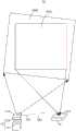
图1是本实用新型的一个实施例的示意图;Fig. 1 is the schematic diagram of an embodiment of the present utility model;
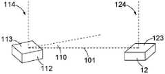
图2是图1所示实施例的部分示意图;Fig. 2 is a partial schematic view of the embodiment shown in Fig. 1;
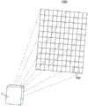
图3是图1所示实施例的部分示意图;Fig. 3 is a partial schematic view of the embodiment shown in Fig. 1;
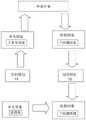
图4是本实用新型的一个实施例的原理示意图;4 is a schematic diagram of an embodiment of the present invention;
图5是本实用新型的一个实施例的示意图;5 is a schematic diagram of an embodiment of the present invention;
图6是图1所示实施例的部分示意图;Figure 6 is a partial schematic view of the embodiment shown in Figure 1;
图7是本实用新型的一个实施例的示意图;7 is a schematic diagram of an embodiment of the present invention;
图8是本实用新型的一个实施例的示意图;8 is a schematic diagram of an embodiment of the present invention;
图9是本实用新型的一个实施例的示意图;9 is a schematic diagram of an embodiment of the present invention;
图10是本实用新型的一个实施例的示意图。FIG. 10 is a schematic diagram of an embodiment of the present invention.
具体实施方式Detailed ways
在对本实用新型实施例的具体描述中,应当理解,当基板、框架、片、层或图案被称为在另一个基板、另一个框架、另一个片、另一个层或另一个图案“上”或“下”时,它可以“直接地”或“间接地”在另一个基板、另一个框架、另一个片、另一个层或另一个图案上,或者还可以存在一个或多个中间层。为了清楚的目的,可以夸大、省略或者示意性地表示说明书附图中的每一个层的厚度和大小。此外,附图中元件的大小并非完全反映实际大小。In the detailed description of embodiments of the present invention, it will be understood that when a substrate, frame, sheet, layer or pattern is referred to as being "on" another substrate, another frame, another sheet, another layer or another pattern Or "under" it may be "directly" or "indirectly" on another substrate, another frame, another sheet, another layer or another pattern, or one or more intervening layers may also be present. The thickness and size of each layer in the drawings of the specification may be exaggerated, omitted or schematically represented for the purpose of clarity. Furthermore, the sizes of elements in the drawings do not fully reflect actual sizes.
本实用新型的一个实施例提供了一种深度检测系统,包括发射模组,用于发射具有参考图案的检测光束;接收模组,用于采集被外部对象反射的具有检测图案的检测光束;其中,所述发射模组和/或接收模组的边缘所在直线相对所述发射模组和接收模组的基线所在直线具有一定夹角;或者所述发射模组边缘所在直线和所述接收模组边缘所在直线具有一定夹角。An embodiment of the present invention provides a depth detection system, including a transmitting module for transmitting a detection beam with a reference pattern; a receiving module for collecting the detection beam with a detection pattern reflected by an external object; wherein , the straight line where the edge of the transmitting module and/or the receiving module is located has a certain angle relative to the straight line where the baseline of the transmitting module and the receiving module is located; or the straight line where the edge of the transmitting module is located and the receiving module The line where the edge is located has a certain angle.
所述发射模组具有面向外部投影空间的发光面,所述发射模组具有和所述发光面垂直的发射轴,所述接收模组具有面向外部投影空间的感光面,所述接收模组具有和所述感光面垂直的感光轴,所述发光面和所述感光面相互平行,或者所述发光面和所述感光面位于同一平面。The transmitting module has a light-emitting surface facing the external projection space, the transmitting module has an emission axis perpendicular to the light-emitting surface, the receiving module has a photosensitive surface facing the external projection space, and the receiving module has a A photosensitive axis perpendicular to the photosensitive surface, the light-emitting surface and the photosensitive surface are parallel to each other, or the light-emitting surface and the photosensitive surface are located on the same plane.
所述发射模组的发光面和/或所述接收模组的感光面的边缘所在直线或其平行线相对所述基线所在直线具有大于0度且小于或等于45度的夹角。所述发射模组的发光面边缘所在直线和所述接收模组的感光面边缘所在直线之间夹角为大于0度且小于或等于45度。同样的,所述检测图案相对所述基线具有一定夹角。所述检测图案的边缘相对所述基线的夹角为大于0度且小于或等于45度。The line where the edge of the light-emitting surface of the transmitting module and/or the photosensitive surface of the receiving module is located or its parallel line has an included angle greater than 0 degrees and less than or equal to 45 degrees relative to the line where the baseline is located. The included angle between the straight line where the edge of the light-emitting surface of the transmitting module is located and the straight line where the edge of the photosensitive surface of the receiving module is located is greater than 0 degrees and less than or equal to 45 degrees. Likewise, the detection pattern has a certain angle relative to the baseline. The included angle between the edge of the detection pattern and the baseline is greater than 0 degrees and less than or equal to 45 degrees.
所述发射模组包括发光阵列和设置在发光阵列上方的衍射光学元件,所述发光阵列用于发射具有参考图案的检测光束,所述衍射光学元件用于将所述发光阵列发射的检测光束进行分束、复制并向空间中投影。所述发光阵列包括多个发光元件,所述多个发光元件的排列形成规则的或不规则的二维图案,所述发光元件为发光二极管或垂直腔面发射激光器。所述发射模组向外部投影区域投影具有参考图案的检测光束,所述接收模组接收感光区域内的具有检测图案的检测光束,所述感光区域为所述投影区域内的一部分。所述参考图案包括多个相同的具有矩形边缘的子参考图案,所述子参考图案的检测长度大于所述子参考图案的宽度。The emission module includes a light-emitting array and a diffractive optical element arranged above the light-emitting array, the light-emitting array is used for emitting a detection beam with a reference pattern, and the diffractive optical element is used for the detection beam emitted by the light-emitting array. Split, copy and project into space. The light-emitting array includes a plurality of light-emitting elements, the arrangement of the plurality of light-emitting elements forms a regular or irregular two-dimensional pattern, and the light-emitting elements are light-emitting diodes or vertical cavity surface emitting lasers. The transmitting module projects the detection beam with the reference pattern to the external projection area, and the receiving module receives the detection beam with the detection pattern in the photosensitive area, and the photosensitive area is a part of the projection area. The reference pattern includes a plurality of identical sub-reference patterns with rectangular edges, and the detection length of the sub-reference patterns is greater than the width of the sub-reference patterns.
本实用新型其他实施例还提供了一种支架,其能够用于上述的深度检测系统,所述支架包括具有长方体形状的主体,所述主体的一个表面具有向内凹陷的第一收纳槽和第二收纳槽,所述第一收纳槽用于收纳所述深度检测系统的发射模组,所示第二收纳槽用于收纳所述深度检测系统的接收模组,所示第一收纳槽和第二收纳槽具有矩形开口,所述第一收纳槽的矩形开口的边缘所在直线和所述第二收纳槽的矩形边缘所在直线具有大于0度且小于或等于45度的夹角。Other embodiments of the present invention also provide a bracket, which can be used for the above-mentioned depth detection system, the bracket includes a main body having a rectangular parallelepiped shape, and one surface of the main body has a first receiving groove and a first receiving groove recessed inward. Two storage slots, the first storage slot is used to store the transmitting module of the depth detection system, the second storage slot shown is used to store the receiving module of the depth detection system, the first storage slot and the second storage slot are shown. The second storage slot has a rectangular opening, and the line where the edge of the rectangular opening of the first storage slot is located and the line where the rectangular edge of the second storage slot is located have an included angle greater than 0 degrees and less than or equal to 45 degrees.
本实用新型其他实施例还提供了一种包括上述深度检测系统或支架的电子装置。Other embodiments of the present invention also provide an electronic device including the above-mentioned depth detection system or bracket.
下面将结合本实用新型实施例中的附图,对本实用新型实施例中的技术方案进行清楚、完整地描述,显然,所描述的实施例仅仅是本实用新型一部分实施例,而不是全部的实施例。基于本实用新型中的实施例,本领域普通技术人员在没有作出创造性劳动前提下所获得的所有其他实施例,都属于本实用新型保护的范围。The technical solutions in the embodiments of the present utility model will be clearly and completely described below with reference to the accompanying drawings in the embodiments of the present utility model. Obviously, the described embodiments are only a part of the embodiments of the present utility model, rather than all the implementations. example. Based on the embodiments of the present invention, all other embodiments obtained by those of ordinary skill in the art without creative work fall within the protection scope of the present invention.
请参阅图1和图2,本实用新型的一个实施例中,一个深度检测系统10包括发射模组11和接收模组12。所述发射模组11和接收模组12邻近或间隔设置。所述发射模组11和接收模组12之间的连线为基线101。所述发射模组11包括发光阵列111和设置在发光阵列上方的衍射光学元件(DOE)112。所述发光阵列111用于在所述深度检测系统10的驱动电路(图未示)的驱动下发射具有参考图案的图案化的检测光束,所述衍射光学元件112用于将所述发光阵列111发射的图案化的检测光束进行分束、复制并向空间中投影。Referring to FIGS. 1 and 2 , in an embodiment of the present invention, a
本实施例或变更实施例中,所述发光阵列111可以包括多个发光元件(图未示),所述多个发光元件的排列形成规则的或不规则的二维图案。所述发光元件可以为发光二极管(Light Emitting Diode,LED),垂直腔面发射激光器(Vertical Cavity SurfaceEmitting Laser,VCSEL)或其他激光发射器等。所述发光阵列111能够用于发射可见光或不可见光,如红外光。In this embodiment or a modified embodiment, the light-emitting
本实施例或变更实施例中,所述接收模组12可以包括图像传感器,例如但不限于可见光图像传感器或红外光图像传感器。所述感光面为所述图像传感器的感光区域。In this embodiment or a modified embodiment, the receiving
所发射模组11的衍射光学元件112具有面向外部投影空间的发光面113,所述发射模组11具有和所述发光面113垂直的发射轴114。所述接收模组12具有面向外部投影空间的感光面123,所述接收模组12具有和所述感光面123垂直的感光轴124。所述发光面113和所述感光面123相互平行或大致相互平行,或者所述发光面113和所述感光面123位于同一平面。本实施例中,所述发光面113和感光面123可以看作位于同一空间平面内。The diffractive
所述发射轴114大致为所述发光面113或所述发射模组11的中心轴,所述发光面113关于所述发射轴114中心对称。所述感光轴124大致为所述感光面123或所述接收模组12的中心轴,所述感光面123关于所述感光轴124中心对称。所述发射模组11和接收模组12间的基线101可以是所述发射轴114和所述感光轴124之间与所述发光面113和感光面123平行的连线。因此所述基线101与所述发射轴114、所述感光轴124垂直。The
所述发光面113大致为矩形,所述感光面123大致为矩形,所述发光面113的边缘所在直线或其平行线与所述基线101所在直线之间具有夹角110。本实施例中,所述夹角110的大小为大于0度小于等于15度。变更实施例中,所述夹角110大小为大于0度小于45度。The light-emitting
本实施例或变更实施例中,所述夹角110是所述发射模组11和所述接收模组12的安装位置导致。所述夹角110可以是安装时将所述发射模组11或所述接收模组12有意识的基于发射轴114或感光轴124旋转一定角度形成,或者是示意具有特定形状、角度的收纳槽的支架来形成满足夹角110的安装位置。In this embodiment or the modified embodiment, the included
所述发射模组11向外部的投影区域1000投影具有参考图案的检测光束。所述接收模组12接收感光区域1010内的具有检测图案的检测光束。所述投影区域1000包含所述感光区域1010,所述感光区域1010为所述投影区域1000内的一部分。The emitting
所述投影区域1000与所述发光面113形状对应,因此所述投影区域1000大致为矩形,边缘为直线。所述感光区域1010与所述感光面123形状对应,因此所述感光区域1010大致为矩形,边缘为直线。所述投影区域1000与所述感光区域1010的边缘之间对应具有夹角110。The
请参阅图3,是图1所示投影区域1000的部分示意图。图3所示投影区域1000包括多个子参考图案1001,所述多个子参考图案1001按照网格排列。所述子参考图案1001大致为的矩形,其边缘与所述基线101同样具有夹角110。本实施例中,所述子参考图案1001按照11*11网格阵列排布。Please refer to FIG. 3 , which is a partial schematic diagram of the
所述检测图案包括多个与所述子参考图案1001对应的子检测图案。通过所述接收模组12接收的具有检测图案的检测光束能够生成与检测图案对应的检测图像,所述检测图像包括多个与所述子检测图案对应的子检测图像。The detection pattern includes a plurality of sub-detection patterns corresponding to the
需要说明的是,本说明书中描述的参考图案是所述投影模组11经衍射光学元件112发射的检测光束所对应具有的图案,所述子参考图案1001具有与所述发光阵列111的发光元件的排布对应的二维图案。所述检测图案是所述发射模组11发射的检测光束被外部对象反射后的检测光束所具有的图案,所述检测图案可以看作是具有参考图案的检测光束被外部对象反射时因为外部对象具有深度信息导致被反射的检测光束产生偏移,从而具有的图案称为检测图案。所述具有检测图案的检测光束能够被所述接收模组12接收或采集,并生成对应的检测图像,所述检测图像可以包括多个发光元件发光形成的检测点。本实用新型上述或变更实施例中,所述具有检测图案的光束可以为投影区域1000内的外部对象反射所述具有参考图案的检测光束形成的具有参考图案的检测光束。It should be noted that the reference pattern described in this specification is the pattern corresponding to the detection light beam emitted by the
图3所示的投影区域1000仅作示意,不应理解为对投影区域1000形状、排列、大小等限定。实际上,所述发射模组11向空间投射光束时,一般会产生由光学元件导致的枕形失真,所述子参考图案1001和所述投影区域1000内参考图案会具有相应扭曲的矩形形状。The
本实施例或变更实施例中,所述检测光束为结构光(Structured Light),可选的,所述检测光束为散斑结构光或编码结构光。In this embodiment or a modified embodiment, the detection beam is structured light (Structured Light). Optionally, the detection beam is speckle structured light or coded structured light.
请参阅图4,是所述深度检测系统10的深度信息检测光学原理示意图。如图4所示,所示深度检测系统10采用三角测量原理检测外部对象的深度信息。根据三角测量原理可得:Please refer to FIG. 4 , which is a schematic diagram of the optical principle of depth information detection of the
1)存在三角形△abc相似于三角形△dec,即,△abc∽△dec,de=X,从而可以得到:1) There is a triangle △abc similar to the triangle △dec, that is, △abc∽△dec, de=X, so we can get:

2)存在△deg∽△chg,因此可以得到:2) There is △deg∽△chg, so we can get:

由公式(1)和公式(2)消除其中的X,可以得到公式(3):By eliminating X in formula (1) and formula (2), formula (3) can be obtained:
3)
其中Δu代表检测图像和参考图像间的偏移量大小,Z代表深度大小。由公式(3),外部对象的深度信息和检测到的偏移量相关联。并且,当Δu代表的偏移大小的数值范围越大时,能够检测到的Z对应的深度的范围越大。由此可得,较大范围的检测图像和参考图像间的偏移量大小能够使得所述深度检测系统10测量到较大范围的深度信息。where Δu represents the offset between the detection image and the reference image, and Z represents the depth. By Equation (3), the depth information of the external object is associated with the detected offset. Moreover, when the numerical range of the offset size represented by Δu is larger, the range of the depth corresponding to Z that can be detected is larger. As a result, a larger range of the offset size between the detected image and the reference image can enable the
请一并参阅图5,所述深度检测系统10进行深度信息检测时,所述深度检测系统10会先截取参考图像中的一部分作为检测块(例如但不限于,3像素*3像素的检测块,或者5像素*5像素的检测块等),然后沿着所述基线101的方向(图4中即为检测长度L的方向)在接收到的检测图像的每个子检测图像内遍历进行比对、计算从而得到检测图像和参考图像的偏移量,进而能够获取外部对象的深度信息。本实施例中,所述检测块可以为所述参考图像中任意一个5像素*5像素大小的方形区域。所述检测块包括多个检测点,通过与所述接收模组12连接的深度检测芯片在所述每个检测点处检测所述子检测图像相对于参考图像的局部横向偏移,从而能够通过三角测量获取对应检测点处的深度坐标或深度信息。Please also refer to FIG. 5 , when the
由于参考图案中的子参考图案内部是不相关的,而相邻的子参考图案通常是高度相关的。所以当外部对象的深度信息对应的横向偏移大于或等于所述子参考图案之间的横向间距时(这里说的横向为沿基线101方向),可能会导致深度信息检测错误或模糊。例如,当外部对象深度对应的横向偏移横跨相邻两个子参考图案时,所述深度检测系统10在对应的子检测图案中无法判断是所述横向位移是横跨相邻两个子检测图案还是属于单一的一个子检测图案。Since sub-reference patterns in a reference pattern are internally uncorrelated, adjacent sub-reference patterns are usually highly correlated. Therefore, when the lateral offset corresponding to the depth information of the external object is greater than or equal to the lateral spacing between the sub-reference patterns (here, the lateral direction refers to the direction along the baseline 101 ), it may cause an error or blur in the detection of the depth information. For example, when the lateral displacement corresponding to the depth of the external object spans across two adjacent sub-reference patterns, the
请参阅图6,是图3所示子参考图案1001的示意图。所述子参考图案1001具有矩形边缘,其包括多个与发光元件排布的二维图案对应的光点1002。所述光点1002与所述发光阵列111上的发光元件一一对应。Please refer to FIG. 6 , which is a schematic diagram of the
对所述深度检测系统10来说,所述检测图像可以是根据所述接收模组12接收的具有检测图案的检测光束经过光电转换得到,所述参考图像可以是预先存储的用于和检测图像比对的图像。例如但不限于,所述参考图像包括和子参考图案1001相同或相对应的图案,这里说的相同指的是参考图像中的检测点和所述子参考图案1001中的光点1002位置、间距、数量均相同;相对应指的是参考图像中的检测点和所述子参考图案1001中的光点1002的位置、间距、数量至少有一项不同。For the
本实施例中,所述光点1002在矩形的子参考图案1001内杂乱分布,从而形成具有高度不相关性的子参考图案1001。这里说的高度不相关性指的是所述子参考图案1001对应的参考图像被一个检测块遍历检测时不能得到和检测块的具有相同图像的区域,或具有和检测块的检测点重合的光点1002的区域。In this embodiment, the
本实施例中,所述发射模组11的发光面113的边缘所在直线相对所述基线101所在直线具有夹角110,所以所述子参考图案1001的边缘在投影空间中相对所述基线101具有夹角110。而所述接收模组12的感光面123的边缘所在直线平行所述基线101所在直线,因此所述接收模组12接收的检测图案相对所述基线101具有同样的夹角110。假定图4中水平方向为沿基线101方向,所述子参考图案1001具有宽度为H、长度为V的矩形边缘,所述子参考图案1001沿基线101方向的检测长度为L。显然地,所述检测长度L大于所述子参考图案1001的宽度H。In this embodiment, the line where the edge of the light-emitting
因此,由于所述深度检测系统10的子参考图案1001和基线101所在方向具有一定夹角110,因此使得沿基线101方向的检测长度L大于所述子参考图案1001的宽度H,同样也就大于所述子检测图案的宽度。因此单个子检测图案对应的子检测图像能够具有更大的横向偏移的测量空间,从而能够在较大范围内精确获取外部对象的深度信息。Therefore, since the
本实用新型上述或变更实施例中,所述接收模组12接收的具有检测图案的检测光束能够用于外部对象的生物特征检测和识别,例如但不限于指纹检测与识别、脸部检测与识别、虹膜检测与识别等。In the above or modified embodiments of the present invention, the detection beam with the detection pattern received by the receiving
本实用新型上述或变更实施例中,所述接收模组12接收的具有检测图案的检测光束能够用于外部对象的二维和/或三维的图形绘制。进一步的实施例中,所述深度检测系统还包括深度检测芯片,所述深度检测芯片能够根据所述接收模组12采集的具有检测图案的检测光束生成对应的检测图像,并通过将所述检测图案和预先存储的参考图案进行比对计算,获得外部对象的深度信息。In the above or modified embodiments of the present invention, the detection beam with detection patterns received by the receiving
本实用新型上述或变更实施例中,所述发射模组11和接收模组12可以分别是单独的芯片单元,也可是集成在一个芯片单元中,图1和图2中发射模组11和接收模组12仅为示意性表示,不代表发射模组11、接收模组12以及它们之间的形状、结构和位置关系的任何限定。In the above or modified embodiments of the present invention, the transmitting
本实用新型所述实施例和变更实施例中,所述发射模组11发射的检测光束能够被外部对象(例如手指或人脸)反射后通过被所述接收模组12接收。In the embodiment and modified embodiments of the present invention, the detection beam emitted by the transmitting
请参阅图7,本实用新型的一个变更实施例中,一个深度检测系统70包括发射模组71和接收模组72。所述发射模组71和接收模组72邻近或间隔设置。所述发射模组71和接收模组72之间的连线定义为基线701。所述发射模组71具有面向外部投影空间的发光面713,所述发射模组71具有和所述发光面713垂直的发射轴714。所述接收模组72具有面向外部投影空间的感光面723,所述接收模组72具有和所述感光面723垂直的感光轴724。所述发光面713和所述感光面723相互平行或大致相互平行,或者所述发光面713和所述感光面723位于同一平面。本实施例中,所述发光面713和感光面723可以看作位于同一空间平面内。Referring to FIG. 7 , in a modified embodiment of the present invention, a
所述发射轴714大致为所述发光面713或所述发射模组71的中心轴,所述发光面713关于所述发射轴714中心对称。所述感光轴724大致为所述感光面723或所述接收模组72的中心轴,所述感光面723关于所述感光轴724中心对称。所述发射模组71和接收模组72间的基线701可以是所述发射轴714和所述感光轴724之间与所述发光面713和感光面723平行的连线。所述基线701与所述发射轴714、所述感光轴724垂直。The
所述发光面713具有大致围成矩形的多个边缘,所述感光面723具有大致围成矩形的多个边缘,所述感光面723的至少一个边缘所在直线或该边缘所在直线的平行线与所述基线701间具有夹角720。本实施例中,所述夹角720的大小为大于0度小于等于15度。变更实施例中,所述夹角720大小为大于0度小于45度。变更实施例中,所述夹角可以为锐角或钝角。The light-emitting
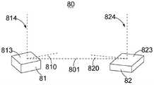
请参阅图8,本实用新型的一个变更实施例中,一个深度检测系统80包括发射模组81和接收模组82。所述发射模组81和接收模组82邻近或间隔设置。所述发射模组81和接收模组82之间的连线定义为基线801。所述发射模组81具有面向外部投影空间的发光面813,所述发射模组81具有和所述发光面813垂直的发射轴814。所述接收模组82具有面向外部投影空间的感光面823,所述接收模组82具有和所述感光面823垂直的感光轴824。所述发光面813和所述感光面823相互平行或大致相互平行,或者所述发光面813和所述感光面823位于同一平面。本实施例中,所述发光面813和感光面823可以看作位于同一空间平面内。Referring to FIG. 8 , in a modified embodiment of the present invention, a
所述发射轴814大致为所述发光面813或所述发射模组81的中心轴,所述发光面813关于所述发射轴814中心对称。所述感光轴824大致为所述感光面823或所述接收模组82的中心轴,所述感光面823关于所述感光轴824中心对称。所述发射模组81和接收模组82之间的基线801可以是所述发射轴814和所述感光轴824之间与所述发光面813和感光面823平行的连线。所述基线801与所述发射轴814、所述感光轴824垂直。The
所述发光面813具有围成矩形的四个边缘,所述感光面823具有围成矩形的四个边缘,所述发光面813的矩形的边缘所在直线或其平行线与所述基线801所在直线之间具有夹角810,所述感光面823的矩形的边缘所在直线或其平行线与所述基线801所在直线之间具有夹角820。所述发光面813的边缘所在直线和感光面823的边缘所在直线不平行。本实施例中,所述夹角810、820的大小为大于0度小于等于15度。变更实施例中,所述夹角810、820大小为大于0度小于45度。变更实施例中,所述夹角可以为锐角或钝角。The light-emitting
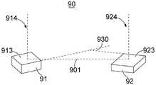
请参阅图9,本实用新型的一个变更实施例中,一个深度检测系统90包括发射模组91和接收模组92。所述发射模组91和接收模组92邻近或间隔设置。所述发射模组91和接收模组92之间的连线定义为基线901。所述发射模组91具有面向外部投影空间的发光面913,所述发射模组91具有和所述发光面913垂直的发射轴914。所述接收模组92具有面向外部投影空间的感光面923,所述接收模组92具有和所述感光面923垂直的感光轴924。所述发光面913和所述感光面923相互平行或大致相互平行,或者所述发光面913和所述感光面923位于同一平面。本实施例中,所述发光面913和感光面923可以看作位于同一空间平面内。Referring to FIG. 9 , in a modified embodiment of the present invention, a
所述发射轴914大致为所述发光面913或所述发射模组91的中心轴,所述发光面913关于所述发射轴914中心对称。所述感光轴924大致为所述感光面923或所述接收模组92的中心轴,所述感光面923关于所述感光轴924中心对称。所述发射模组91和接收模组92间的基线901可以是所述发射轴914和所述感光轴924之间与所述发光面913和感光面923平行的连线。所述基线901与所述发射轴914、所述感光轴924垂直。所述发光面913大致具有矩形边缘,所述感光面923大致具有矩形边缘,所述发光面913的矩形边缘所在直线或其平行线与所述感光面923的矩形边缘所在直线或其平行线之间具有夹角930。所述夹角930可以为大于0度且小于等于45度范围之间。The
请参阅图10,是本实用新型一种用于深度检测系统的支架的一个实施例的示意图,所述支架30包括主体33,所述主体33大致具有长方体形状。所述主体33的一个表面具有向内凹陷的第一收纳槽31和第二收纳槽32。所述第一收纳槽31可用于收纳图1所示的发射模组11,所示第二收纳槽32可用于收纳图1所示的接收模组12。所示第一收纳槽31和第二收纳槽32具有矩形开口,所述第一收纳槽31的矩形开口的边缘所在直线和所述第二收纳槽32的矩形开口的边缘所在直线具有夹角310。所述夹角310可以为大于0度且小于或等于45度的角。Please refer to FIG. 10 , which is a schematic diagram of an embodiment of a bracket for a depth detection system of the present invention. The
变更实施例中,所述支架30的所述第一收纳槽31和第二收纳槽32可以通过胶水分别与发射模组11、接收模组12固定在一起。In a modified embodiment, the first receiving
变更实施例中,所述支架30还可以用于上述实施例中描述的深度检测系统70、80、90或其他变更实施例中。In a modified embodiment, the
所述深度检测系统10、70、80、90通过采集外部对象反射的检测光束能够获取外部对象的二维的图像信息或生物特征信息。所述深度检测系统10、70、80、90还可以包括处理器(图未示),所述处理器能够计算接收的检测光束关于参考图像的偏移进而获得外部对象的深度信息。进一步的,所述处理器还预先存储生物特征信息数据,所述处理器能够通过将获得的外部对象的二维信息和/或深度信息和预先存储的生物特征信息数据进行比对,从而实现外部对象的生物特征检测和识别,例如但不限于:指纹识别,脸部识别,虹膜识别等。The
通过对外部对象的生物特征进行检测和识别,所述深度检测系统70、80、90可应用于电子装置(如:手机)的锁定或解锁,在线支付业务验证,金融系统或公安系统的身份验证,门禁系统的通行验证等多种产品和应用场景。By detecting and identifying the biometric features of external objects, the
本实用新型上述实施例或变更实施例中,所述检测光束为不可见光,较佳的为波段为850~1000纳米(nm)之间的红外光。In the above-mentioned embodiments or modified embodiments of the present invention, the detection beam is invisible light, preferably infrared light with a wavelength band between 850 and 1000 nanometers (nm).
本实用新型其他或变更实施例中,所述检测光束还可以为可见光,不可见光,紫外光,红外光,超声波,电磁波中等的一种或几种。In other or modified embodiments of the present invention, the detection beam may also be one or more of visible light, invisible light, ultraviolet light, infrared light, ultrasonic wave, and electromagnetic wave.
本实用新型其他或变更实施例中,所述检测光束可以为泛光,散斑结构光,编码结构光,调制脉冲信号中一种或多种。In other or modified embodiments of the present invention, the detection beam may be one or more of flood light, speckle structured light, coded structured light, and modulated pulse signal.
本实用新型所述实施例或变更实施例中,所述发射模组11、71、81、91的数量可以为一个或多个,所述接收模组12、72、82、92的数量可以为一个或多个,所述发射模组和接收模组之间可基于飞行时间(Time of Flight,TOF),结构光(Structured Light),双目立体视觉(Binocular Stereo Vision)等技术用于绘制外部对象的二维和/或三维图像,或者采集和识别外部对象的二维和/或三维生物特征信息,例如指纹识别或脸部识别。In the embodiment or modified embodiment of the present invention, the number of the transmitting
本实用新型所述实施例或变更实施例中,所述发射模组11、71、81、91可以包括垂直腔面发射激光器(Vertical Cavity Surface Emitting Laser,VCSEL),或发光二极管(LED),或其他类型发光芯片。所述接收模组12、72、82、92可以包括红外图像传感器,能够接收红外光束并转换为对应电信号。其他或变更实施例中,所述接收单模组12、72、82、92还可以包括可见光图像传感器,或其他类型光电转换芯片。In the embodiment or modified embodiment of the present invention, the
本实用新型还提供一种电子装置,包括上述的深度检测系统10、70、80、90或其变更实施例,所述电子装置可以是手机,平板电脑,智能手表,增强现实/虚拟现实装置,人体动作检测装置,自动驾驶汽车,智能家居设备,安防设备,门禁设备,智能机器人或其他具有能够用于对象生物特征检测和识别的电子装置,或上述之组件。The present invention also provides an electronic device, including the above-mentioned
相较于现有技术,本实用新型深度检测系统的发射模组和/或接收模组的边缘或其所在直线与所述基线之间具有一定夹角,或者发射模组边缘所在直线和接收模组的边缘所在直线具有一定夹角,从而使得所述深度检测系统具有较大的能够精确测量的深度范围。本实用新型支架能够用于上述深度检测系统,本实用新型电子装置包括上述深度检测系统。因此本实用新型深度检测系统及其支架和电子装置具有较大的深度信息的精确检测范围。Compared with the prior art, there is a certain angle between the edge of the transmitting module and/or the receiving module of the depth detection system of the present invention or the straight line where it is located and the baseline, or the straight line where the edge of the transmitting module is located and the receiving module are The straight line where the edge of the group is located has a certain included angle, so that the depth detection system has a larger depth range that can be accurately measured. The bracket of the present invention can be used for the above-mentioned depth detection system, and the electronic device of the present invention includes the above-mentioned depth detection system. Therefore, the depth detection system of the present invention, its bracket and the electronic device have a larger accurate detection range of depth information.
需要说明的是,本领域技术人员可以理解,在不付出创造性劳动的前提下,本实用新型实施例的部分或全部,以及对于实施例的部分或全部的变形、替换、变更、拆分、组合、扩展等均应认为被本实用新型的实用新型创造思想所涵盖,属于本实用新型的保护范围。It should be noted that those skilled in the art can understand that without creative work, part or all of the embodiments of the present invention, as well as some or all of the modifications, replacements, changes, splits, and combinations of the embodiments , expansion, etc. should be considered to be covered by the inventive idea of the present utility model, and belong to the protection scope of the present utility model.
在本说明书中对于“一个实施例”、“实施例”、“示例实施例”等的任何引用表示结合该实施例描述的特定特征、结构或特性被包括在本实用新型的至少一个实施例中。在本说明书中不同位置出现的这种短语并不一定全部指相同的实施例。另外,当结合任何实施例描述特定的特征或结构时,所主张的是,结合这些实施例的其它实施例来实现这种特征或结构在本领域技术人员的技术范围内。Any reference in this specification to "one embodiment," "an embodiment," "an example embodiment," etc. means that a particular feature, structure, or characteristic described in connection with the embodiment is included in at least one embodiment of the present invention . The appearances of such phrases in various places in this specification are not necessarily all referring to the same embodiment. Additionally, when a particular feature or structure is described in conjunction with any embodiment, it is claimed that it is within the skill of those skilled in the art to implement such feature or structure in conjunction with other embodiments of those embodiments.
本实用新型说明书中可能出现的“长度”、“宽度”、“上”、“下”、“前”、“后”、“背面”、“正面”、“竖直”、“水平”、“顶部”、“底部”、“内部”、“外部”等指示的方位或位置关系为基于附图所示的方位或位置关系,仅是为了便于描述本实用新型实施例和简化描述,而不是指示或暗示所指的装置或元件必须具有特定的方位、以特定的方位构造和操作,因此不能理解为对本实用新型的限制。相似的标号和字母在附图中表示类似项,因此,一旦某一项在一个附图中被定义,则在随后的附图中不需要对其进行进一步定义和解释。同时,在本实用新型的描述中,术语“第一”、“第二”等仅用于区分描述,而不能理解为指示或暗示相对重要性。在本实用新型的描述中,“多种”或“多个”的含义是至少两种或两个,除非另有明确具体的限定。本实用新型的描述中,还需要说明的是,除非另有明确的规定和限定,“设置”、“安装”、“连接”应做广义理解,例如,可以是固定连接,也可以是可拆卸连接,或一体地连接;可以是机械连接,也可以是电连接;可以是直接连接,也可以是通过中间媒介间接连接,可以是两个元件内部的连通。对于本领域的普通技术人员而言,可以具体情况理解上述术语在本实用新型中的具体含义。The "length", "width", "upper", "lower", "front", "rear", "rear", "front", "vertical", "horizontal", "rear", The orientation or positional relationship indicated by "top", "bottom", "internal", "external", etc. is based on the orientation or positional relationship shown in the drawings, and is only for the convenience of describing the embodiments of the present invention and simplifying the description, rather than indicating Or imply that the referred device or element must have a specific orientation, be constructed and operate in a specific orientation, and therefore should not be construed as a limitation of the present invention. Like numerals and letters refer to like items in the figures, so once an item is defined in one figure, no further definition and explanation are required in subsequent figures. Meanwhile, in the description of the present invention, the terms "first", "second" and the like are only used to distinguish the description, and cannot be understood as indicating or implying relative importance. In the description of the present invention, "multiple" or "plurality" means at least two or two, unless otherwise expressly and specifically defined. In the description of the present utility model, it should also be noted that, unless otherwise expressly specified and limited, "setting", "installation" and "connection" should be understood in a broad sense, for example, it may be a fixed connection or a detachable connection. Connection, or integral connection; may be mechanical connection or electrical connection; may be direct connection or indirect connection through an intermediate medium, and may be internal communication between two elements. For those of ordinary skill in the art, the specific meanings of the above terms in the present invention can be understood in specific situations.
以上所述,仅为本实用新型的具体实施方式,但本实用新型的保护范围并不局限于此,任何熟悉本技术领域的技术人员在本实用新型揭露的技术范围内,可轻易想到变化或替换,都应涵盖在本实用新型的保护范围之内。权利要求书中所使用的术语不应理解为将实用新型限制于本说明书中所公开的特定实施例。因此,本实用新型的保护范围应以所述权利要求的保护范围为准。The above are only specific embodiments of the present invention, but the protection scope of the present invention is not limited to this. Replacement should be covered within the protection scope of the present invention. The terms used in the claims should not be construed to limit the utility model to the specific embodiments disclosed in this specification. Therefore, the protection scope of the present invention should be based on the protection scope of the claims.
Claims (10)
Applications Claiming Priority (2)
| Application Number | Priority Date | Filing Date | Title |
|---|---|---|---|
| CN201920374818 | 2019-03-23 | ||
| CN2019203748188 | 2019-03-23 |
Publications (1)
| Publication Number | Publication Date |
|---|---|
| CN211060850Utrue CN211060850U (en) | 2020-07-21 |
Family
ID=70627821
Family Applications (2)
| Application Number | Title | Priority Date | Filing Date |
|---|---|---|---|
| CN201921543845.XUActiveCN210570528U (en) | 2019-03-23 | 2019-09-17 | Depth detection system and its bracket and electronics |
| CN201921543846.4UActiveCN211060850U (en) | 2019-03-23 | 2019-09-17 | Depth detection system and its bracket and electronics |
Family Applications Before (1)
| Application Number | Title | Priority Date | Filing Date |
|---|---|---|---|
| CN201921543845.XUActiveCN210570528U (en) | 2019-03-23 | 2019-09-17 | Depth detection system and its bracket and electronics |
Country Status (1)
| Country | Link |
|---|---|
| CN (2) | CN210570528U (en) |
Cited By (1)
| Publication number | Priority date | Publication date | Assignee | Title |
|---|---|---|---|---|
| CN116482708A (en)* | 2023-03-23 | 2023-07-25 | 奥比中光科技集团股份有限公司 | TOF and structured light combined depth camera, depth detection method thereof and sweeper |
Families Citing this family (1)
| Publication number | Priority date | Publication date | Assignee | Title |
|---|---|---|---|---|
| CN109974611B (en)* | 2019-03-23 | 2023-07-21 | 柳州阜民科技有限公司 | Depth detection system, support and electronic device thereof |
- 2019
- 2019-09-17CNCN201921543845.XUpatent/CN210570528U/enactiveActive
- 2019-09-17CNCN201921543846.4Upatent/CN211060850U/enactiveActive
Cited By (1)
| Publication number | Priority date | Publication date | Assignee | Title |
|---|---|---|---|---|
| CN116482708A (en)* | 2023-03-23 | 2023-07-25 | 奥比中光科技集团股份有限公司 | TOF and structured light combined depth camera, depth detection method thereof and sweeper |
Also Published As
| Publication number | Publication date |
|---|---|
| CN210570528U (en) | 2020-05-19 |
Similar Documents
| Publication | Publication Date | Title |
|---|---|---|
| US11310479B2 (en) | Non-uniform spatial resource allocation for depth mapping | |
| US11398085B2 (en) | Systems, methods, and media for directly recovering planar surfaces in a scene using structured light | |
| US9826216B1 (en) | Systems and methods for compact space-time stereo three-dimensional depth sensing | |
| US20210201517A1 (en) | Depth sensing with a ranging sensor and an image sensor | |
| US12265232B2 (en) | Beam-splitting optical module and manufacturing method thereof | |
| TW201942541A (en) | Three-dimensional sensing module | |
| CN101169824B (en) | Fingerprint identification device and method | |
| CN211060850U (en) | Depth detection system and its bracket and electronics | |
| WO2013035553A1 (en) | User interface display device | |
| KR20100112853A (en) | Apparatus for detecting three-dimensional distance | |
| WO2017011171A1 (en) | Video imaging to assess specularity | |
| WO2019213865A1 (en) | Light source module, image acquisition device, identity recognition device and electronic apparatus | |
| WO2022137940A1 (en) | Spatial floating image display apparatus | |
| CN114089348A (en) | Structured light projector, structured light system, and depth calculation method | |
| KR102668245B1 (en) | Apparatus and method for measuring depth of three dimensions | |
| US9992472B1 (en) | Optoelectronic devices for collecting three-dimensional data | |
| CN109068117A (en) | Light source module group, 3D imaging system, identity recognition device and electronic equipment | |
| US9285894B1 (en) | Multi-path reduction for optical time-of-flight | |
| WO2019213861A1 (en) | Light source module, image acquisition device, identity recognition device, and electronic apparatus | |
| CN209448840U (en) | Light source module group, 3D imaging system, identity recognition device and electronic equipment | |
| CN209962288U (en) | Depth detection system and electronic device | |
| TW202004669A (en) | Method for multi-spectrum high-precision identification of objects capable of being widely used in security monitoring, industrial monitoring, face recognition, vehicle image recognition and door opening | |
| CN109974611B (en) | Depth detection system, support and electronic device thereof | |
| CN210402379U (en) | Lens assembly, imaging device and biological characteristic detection system | |
| CN111089612A (en) | Optical sensors and optical sensing systems |
Legal Events
| Date | Code | Title | Description |
|---|---|---|---|
| GR01 | Patent grant | ||
| GR01 | Patent grant | ||
| TR01 | Transfer of patent right | ||
| TR01 | Transfer of patent right | Effective date of registration:20250606 Address after:300308 Tianjin City Binhai New Area Free Trade Pilot Zone (Airport Economic Zone) Airport International Logistics Park Second Street No. 1 Room 312 Patentee after:Zhiyun Zhongka Supply Chain Management (Tianjin) Co.,Ltd. Country or region after:China Address before:545000 No.105, 2nd floor, building 2, 29 Xinliu Avenue, Liuzhou City, Guangxi Zhuang Autonomous Region Patentee before:LIUZHOU FUMIN TECHNOLOGY Co.,Ltd. Country or region before:China |