CN211055423U - Pharmaceutical packaging equipment - Google Patents
Pharmaceutical packaging equipmentDownload PDFInfo
- Publication number
- CN211055423U CN211055423UCN201922095644.4UCN201922095644UCN211055423UCN 211055423 UCN211055423 UCN 211055423UCN 201922095644 UCN201922095644 UCN 201922095644UCN 211055423 UCN211055423 UCN 211055423U
- Authority
- CN
- China
- Prior art keywords
- cylinder
- frame
- roller
- baffle
- subassembly
- Prior art date
- Legal status (The legal status is an assumption and is not a legal conclusion. Google has not performed a legal analysis and makes no representation as to the accuracy of the status listed.)
- Expired - Fee Related
Links
- 238000009512pharmaceutical packagingMethods0.000titleclaimsdescription14
- 238000007789sealingMethods0.000claimsabstractdescription79
- 239000000463materialSubstances0.000claimsabstractdescription16
- 230000005540biological transmissionEffects0.000claimsabstractdescription11
- 238000012856packingMethods0.000claimsabstract4
- 230000008094contradictory effectEffects0.000claims1
- 238000004806packaging method and processMethods0.000description25
- 239000000843powderSubstances0.000description8
- 238000010586diagramMethods0.000description7
- 238000005520cutting processMethods0.000description6
- 238000010438heat treatmentMethods0.000description6
- 238000000034methodMethods0.000description2
- 238000000465mouldingMethods0.000description2
- 230000007812deficiencyEffects0.000description1
- 230000005484gravityEffects0.000description1
- 238000006467substitution reactionMethods0.000description1
- 230000007306turnoverEffects0.000description1
Images


Landscapes
- Package Closures (AREA)
Abstract
Description
Translated fromChinese技术领域technical field
本实用新型涉及一种制药包装设备。The utility model relates to a pharmaceutical packaging equipment.
背景技术Background technique
在制药过程中,为了便于药材粉末的运输,需要将粉末按一定量包装起来,为了简化包装袋的成型,采用两端开口,中间封闭的薄膜进行包装成型,依次要进行送膜、封一端口、剪切、给袋、开袋、充填、封另一端口、下料,因此需要一台自动化设备完成上述操作。In the pharmaceutical process, in order to facilitate the transportation of medicinal powder, it is necessary to pack the powder in a certain amount. In order to simplify the molding of the packaging bag, a film with both ends open and the middle closed is used for packaging and molding, followed by film feeding and sealing a port. , cutting, bagging, opening, filling, sealing another port, and cutting, so an automated equipment is required to complete the above operations.
发明内容SUMMARY OF THE INVENTION
本实用新型克服了现有技术的不足,提供了一种制药包装设备,其能实现自动化包装,效率高。The utility model overcomes the deficiencies of the prior art and provides a pharmaceutical packaging equipment, which can realize automatic packaging and has high efficiency.
为了实现上述目的,本实用新型采用的技术方案是:一种制药包装设备,包括机架,所述机架上沿横向依次设有薄膜上料组件、动力源组件、第一封口组件和切刀组件,所述机架由上至下依次设有漏斗、第二封口组件和吸盘组件,吸盘组件包括沿横向设置的第一吸盘和第二吸盘,第一吸盘和第二吸盘之间构成沿竖直方向设置的开袋通道,机架上设有驱动第一吸盘和第二吸盘相向或相背伸缩移动的第一驱动组件,所述机架上还设有可将包装袋传输至开袋通道处的传输组件,所述机架在开袋通道的下方还设有用于支撑包装袋的支撑组件。In order to achieve the above purpose, the technical scheme adopted by the present invention is: a pharmaceutical packaging equipment, including a frame, on which a film feeding assembly, a power source assembly, a first sealing assembly and a cutter are arranged in sequence along the transverse direction. The rack is provided with a funnel, a second sealing assembly and a suction cup assembly in sequence from top to bottom. The suction cup assembly includes a first suction cup and a second suction cup arranged in the transverse direction. A bag opening channel arranged in a straight direction, the frame is provided with a first drive assembly that drives the first suction cup and the second suction cup to move toward or away from each other telescopically, and the frame is also provided with a packaging bag that can be transported to the bag opening channel The frame is also provided with a support assembly for supporting the packaging bag below the bag opening channel.
通过采用上述方案,其中竖直方向为垂直于水平面的方向,横向和纵向分别平行于水平面,横向与纵向相互垂直,薄膜经薄膜上料组件进行上料,动力源组件可带动薄膜进行传输,第一封口组件可对薄膜进行封口,然后通过切刀组件将薄膜剪切成若干个包装袋,包装袋(三边已封好,一边开口),包装袋可通过传输组件由下至上或从一侧翻转传输至开袋通道处,包装袋的袋口朝上,第一驱动组件可驱动第一吸盘和第二吸盘吸开袋口,漏斗位于包装袋上方,药材粉末受重力作用可掉落至袋底,包装质量高,支撑组件可对包装袋起到支撑作用,在填充药材粉末时,第一吸盘和第二吸盘不会脱离袋口,其能实现自动化包装,效率高。By adopting the above solution, the vertical direction is the direction perpendicular to the horizontal plane, the transverse direction and the longitudinal direction are respectively parallel to the horizontal plane, and the transverse direction and the longitudinal direction are perpendicular to each other. The sealing unit can seal the film, and then cut the film into several packaging bags by the cutter unit. Turn over and transfer to the bag opening channel, the bag mouth of the packaging bag is facing upward, the first drive assembly can drive the first suction cup and the second suction cup to suck open the bag mouth, the funnel is located above the packaging bag, and the medicinal powder can be dropped to the bag by gravity At the bottom, the packaging quality is high, and the support component can support the packaging bag. When filling the medicinal powder, the first suction cup and the second suction cup will not be separated from the bag mouth, which can realize automatic packaging and high efficiency.
本实用新型的进一步设置是:所述漏斗的下端设有出料口,机架上设有用于通断出料口的挡板,所述挡板铰接设置在漏斗上,挡板的端部摆动至袋口处并可将袋口撑开,机架上设有驱动挡板摆动的驱动件。The utility model is further provided as follows: the lower end of the funnel is provided with a discharge port, the frame is provided with a baffle for opening and closing the discharge port, the baffle is hingedly arranged on the funnel, and the end of the baffle swings It reaches the mouth of the bag and can open the mouth of the bag, and the frame is provided with a driving member for driving the baffle to swing.
通过采用上述方案,挡板不仅可采用铰接的方式通断出料口,还能通过滑移的方式通断出料口,当漏斗的挡板在驱动件的带动下向下翻转时,挡板不仅可打开出料口,便于向袋内填充药材粉末,挡板在摆动时也可顺势将袋口撑开,开袋更加充分,便于药材粉末进入包装袋内。By adopting the above solution, the baffle plate can not only connect and disconnect the discharge port by hinge, but also open and close the discharge port by sliding. Not only can the discharge port be opened, it is convenient to fill the bag with medicinal powder, and the baffle can also open the mouth of the bag when it swings, so that the bag can be opened more fully, so that the medicinal powder can enter the packaging bag.
本实用新型的进一步设置是:传输组件包括转动设置在机架上的转动座,所述转动座上设有输送气缸,输送气缸的伸缩杆上连接有第三吸盘。The utility model is further provided as follows: the transmission assembly includes a rotating seat rotatably arranged on the frame, the rotating seat is provided with a conveying cylinder, and the telescopic rod of the conveying cylinder is connected with a third suction cup.
通过采用上述方案,转动座由电机和传动轴带动并转动设置在机架上,第三吸盘将横向传输的包装袋吸起,然后转动座转动90度,将包装袋传输至开袋通道处,直到第一吸盘和第二吸盘吸住袋口,第三吸盘缩回,并随转动座转动复位,便于下个包装袋的传送。By adopting the above scheme, the rotating base is driven by the motor and the transmission shaft and is rotatably arranged on the frame, the third suction cup sucks up the laterally transported packaging bag, and then the rotating base rotates 90 degrees to transport the packaging bag to the opening channel, Until the first suction cup and the second suction cup suck the bag mouth, the third suction cup retracts, and rotates and resets with the rotating base, so as to facilitate the transfer of the next packaging bag.
本实用新型的进一步设置是:所述挡板包括相对设置的第一挡板和第二挡板,第一挡板的铰接轴和第二挡板的铰接轴分别沿纵向设置,第一挡板和第二挡板由驱动件驱动同时向下摆动时,可将袋口的两侧同时撑开。The utility model is further provided as follows: the baffle includes a first baffle and a second baffle arranged oppositely, the hinge shaft of the first baffle and the hinge shaft of the second baffle are respectively arranged in the longitudinal direction, the first baffle When the second baffle plate and the second baffle plate are driven by the driving member and swing downward at the same time, both sides of the bag mouth can be opened at the same time.
通过采用上述方案,第一挡板和第二挡板左右对称铰接设置在出料口处,第一挡板与其上的铰接轴固定或一定设置,第二挡板与其上的铰接轴固定或一定设置,当第一挡板和第二挡板摆动至水平位置时,第一挡板和第二挡板配合可关断出料口,当第一挡板和第二挡板一起向下翻转时,不仅可打开出料口,也可顺势将袋口向两侧撑开。By adopting the above solution, the first baffle and the second baffle are hinged left and right symmetrically at the discharge port, the first baffle is fixed or fixed with the hinge shaft on it, and the second baffle is fixed or fixed with the hinge shaft on it. Set, when the first baffle and the second baffle swing to the horizontal position, the first baffle and the second baffle cooperate to close the discharge port, when the first baffle and the second baffle turn down together , not only can open the discharge port, but also can open the bag mouth to both sides.
本实用新型的进一步设置是:所述支撑组件包括支撑气缸和支撑座,支撑气缸固定设置在机架上,支撑气缸的伸缩杆沿竖直方向设置,支撑气缸的伸缩杆的端部与支撑座固定连接。The utility model is further provided as follows: the support assembly includes a support cylinder and a support seat, the support cylinder is fixedly arranged on the frame, the telescopic rod of the support cylinder is arranged in the vertical direction, and the end of the telescopic rod of the support cylinder is connected to the support base Fixed connection.
通过采用上述方案,在传输机构带动包装袋传输时,支撑气缸带动支撑座下移,避免干涉,需要填充药材粉末时,支撑气缸带动支撑座上移,使得包装袋的下端抵设在支撑座上,待包装袋封口后,支撑座在支撑气缸的带动下向下移动,可进行后续下料操作。By adopting the above solution, when the transmission mechanism drives the packaging bag to transmit, the supporting cylinder drives the supporting seat to move down to avoid interference, and when the medicinal powder needs to be filled, the supporting cylinder drives the supporting seat to move up, so that the lower end of the packaging bag abuts on the supporting seat , After the packaging bag is sealed, the support seat moves down under the drive of the support cylinder, and the subsequent unloading operation can be performed.
本实用新型的进一步设置是:所述机架上还设有下料斜面,下料斜面的下端处设有收纳盒,所述机架在对应下料斜面的上端处设有推料组件,推料组件包括推料气缸和推板,推料气缸的伸缩杆沿横向设置,推料气缸固定设置在机架上,推料气缸的伸缩杆的端部与推板固定连接。The utility model is further provided as follows: the rack is further provided with a blanking slope, the lower end of the blanking slope is provided with a storage box, and the rack is provided with a pushing component at the upper end corresponding to the blanking slope, and the The material assembly includes a material pushing cylinder and a pushing plate, the telescopic rod of the material pushing cylinder is arranged horizontally, the material pushing cylinder is fixedly arranged on the frame, and the end of the telescopic rod of the material pushing cylinder is fixedly connected with the pushing plate.
通过采用上述方案,支撑座向下移动至下料斜面的上端位置,停止移动,此时推料气缸带动推板横向移动,可将支撑座上的包装袋推至下料斜面处,包装袋可沿下料斜面滑落至收纳盒内,完成下料操作。By adopting the above solution, the support seat moves down to the upper end of the feeding slope and stops moving. At this time, the pushing cylinder drives the push plate to move laterally, and the packaging bag on the supporting seat can be pushed to the feeding slope, and the packaging bag can be moved. Slide it down into the storage box along the cutting slope to complete the cutting operation.
本实用新型的进一步设置是:第一吸盘和第二吸盘分别至少设置有一个,所述第一驱动组件包括固定设置在机架上的第一气缸和第二气缸,第一气缸的伸缩杆和第二气缸的伸缩杆分别沿横向设置,第一吸盘安装在第一气缸的伸缩杆上,第二吸盘安装在第二气缸的伸缩杆上。The utility model is further provided as follows: the first suction cup and the second suction cup are respectively provided with at least one, the first drive assembly includes a first air cylinder and a second air cylinder fixed on the frame, the telescopic rod of the first air cylinder and the The telescopic rods of the second cylinder are respectively arranged in the lateral direction, the first suction cup is mounted on the telescopic rod of the first cylinder, and the second suction cup is mounted on the telescopic rod of the second cylinder.
通过采用上述方案,第一吸盘至少设置一个,可由一个第一气缸带动,也可由多个第一气缸带动,第二吸盘至少设置一个,可由一个第二气缸带动,也可由多个第二气缸带动。By adopting the above solution, at least one first suction cup is provided, which can be driven by one first cylinder or by multiple first cylinders, and at least one second suction cup is provided, which can be driven by one second cylinder or by multiple second cylinders .
本实用新型的进一步设置是:所述驱动件包括第三气缸和第四气缸,第三气缸和第四气缸分别铰接设置在机架上,第三气缸的伸缩杆通过第一连杆与第一挡板连接,第四气缸的伸缩杆通过第二连杆与第二挡板连接,第一连杆一端铰接在第三气缸的伸缩杆上,另一端固定或一体设置在第一挡板的铰接轴上,第二连杆一端铰接在第四气缸的伸缩杆上,另一端固定或一体设置在第二挡板的铰接轴上。The utility model is further provided as follows: the driving member includes a third air cylinder and a fourth air cylinder, the third air cylinder and the fourth air cylinder are respectively hingedly arranged on the frame, and the telescopic rod of the third air cylinder is connected to the first air cylinder through the first connecting rod. The baffle is connected, the telescopic rod of the fourth cylinder is connected with the second baffle through the second connecting rod, one end of the first connecting rod is hinged on the telescopic rod of the third cylinder, and the other end is fixed or integrally arranged on the hinge of the first baffle On the shaft, one end of the second connecting rod is hinged on the telescopic rod of the fourth cylinder, and the other end is fixed or integrally arranged on the hinge shaft of the second baffle.
通过采用上述方案,当第三气缸和第四气缸的伸缩杆伸出时,第一挡板和第二挡板向下摆动,从而打开出料口,撑开袋口;当第三气缸和第四气缸的伸缩杆缩回时,第一挡板和第二挡板向上摆动,从而关闭出料口,结构简单,传动稳定,当然也可以通过一个气缸同时控制第一挡板和第二挡板摆动,还可以通过电机进行控制。By adopting the above solution, when the telescopic rods of the third and fourth cylinders are extended, the first baffle and the second baffle swing downward, thereby opening the discharge port and opening the bag opening; When the telescopic rod of the four-cylinder is retracted, the first baffle and the second baffle swing upward, thereby closing the discharge port. The structure is simple and the transmission is stable. Of course, the first baffle and the second baffle can be simultaneously controlled by one cylinder. Swing can also be controlled by a motor.
本实用新型的进一步设置是:所述第二封口组件包括相对设置的第一热封块和第二热封块,第一热封块和第二热封块沿纵向设置,第一热封块和第二热封块可沿横向滑移的设置在机架上,机架上设有驱动第一热封块和第二热封块相互靠近或远离的第二驱动组件,所述机架上沿横向设有导轨,所述第一热封块通过第一安装座设置在机架上,第一热封块固定设置在第一安装座上,所述第二热封块通过第二安装座设置在机架上,第二热封块固定设置在第二安装座上,第一安装座和第二安装座分别与导轨导向滑移配合,第二驱动组件包括固定设置在机架上的第五气缸和第六气缸,第五气缸和第六气缸的伸缩杆分别沿纵向设置,第五气缸的伸缩杆与第一安装座连接,第六气缸的伸缩杆与第二安装座连接。A further arrangement of the present invention is that: the second sealing assembly includes a first heat sealing block and a second heat sealing block which are oppositely arranged, the first heat sealing block and the second heat sealing block are arranged in the longitudinal direction, and the first heat sealing block The frame and the second heat-sealing block can be slidably arranged on the frame, and the frame is provided with a second drive assembly that drives the first heat-sealing block and the second heat-sealing block to approach or move away from each other. A guide rail is provided along the transverse direction, the first heat-sealing block is arranged on the frame through the first mounting seat, the first heat-sealing block is fixedly arranged on the first mounting seat, and the second heat-sealing block is arranged through the second mounting seat Set on the frame, the second heat sealing block is fixed on the second mounting seat, the first mounting seat and the second mounting seat are respectively matched with the guide rail for guiding and sliding, and the second drive assembly includes a first mounting seat fixed on the frame. The fifth cylinder and the sixth cylinder, the telescopic rods of the fifth cylinder and the sixth cylinder are respectively arranged longitudinally, the telescopic rod of the fifth cylinder is connected with the first mounting seat, and the telescopic rod of the sixth cylinder is connected with the second mounting seat.
通过采用上述方案,第一热封块和第二热封块内分别设有加热管,加热管通电后可发热,当包装袋填充完药材粉末后,第一热封块和第二热封块由第二驱动组件驱动配合抵压袋口,从而可实现袋口的热封操作,结构简单,位置设计合理,第一安装座和第二安装座沿导轨滑移,滑移稳定,通过第五气缸控制第一安装座移动和第六气缸控制第二安装座移动,结构简单,控制方便。By adopting the above solution, the first heat-sealing block and the second heat-sealing block are respectively provided with heating pipes, which can generate heat after being energized. After the packaging bag is filled with the medicinal powder, the first heat-sealing block and the second heat-sealing block The second drive assembly is driven and cooperated to press the bag mouth, so that the heat sealing operation of the bag mouth can be realized. The structure is simple and the position design is reasonable. The first mounting seat and the second mounting seat slide along the guide rail, and the sliding is stable. The cylinder controls the movement of the first mounting seat and the sixth cylinder controls the movement of the second mounting seat, with simple structure and convenient control.
本实用新型的更进一步设置是:所述第一封口组件包括相对设置的上热封辊和下热封辊,上热封辊和下热封辊沿纵向转动设置在机架上,上热封辊和下热封辊抵触配合,所述切刀组件包括相对设置的上切刀辊和下切刀辊,上切刀辊和下切刀辊沿纵向转动设置在机架上,上切刀辊和下切刀辊抵触配合,所述动力源组件包括相对设置的上驱动辊和下驱动辊,上驱动辊和下驱动辊沿纵向转动设置在机架上,薄膜上料组件包括上料辊、传送辊和涨紧辊,传送辊位于上料辊和涨紧辊之间,涨紧辊靠近动力源组件设置。A further configuration of the present invention is that: the first sealing assembly includes an upper heat-sealing roller and a lower heat-sealing roller arranged oppositely, the upper heat-sealing roller and the lower heat-sealing roller are longitudinally rotated and arranged on the frame, and the upper heat-sealing roller The roller and the lower heat-sealing roller are in contact with each other, and the cutter assembly includes an upper cutter roller and a lower cutter roller arranged opposite to each other. The knife rollers are in contact with each other, the power source assembly includes an oppositely arranged upper driving roller and a lower driving roller, the upper driving roller and the lower driving roller are longitudinally rotated and arranged on the frame, and the film feeding assembly includes a feeding roller, a conveying roller and a Tensioning roller, the conveying roller is located between the feeding roller and the tensioning roller, and the tensioning roller is set close to the power source assembly.
通过采用上述方案,上热封辊、下热封辊、上切刀辊、下切刀辊、上驱动辊和下驱动辊可由同一个驱动电机驱动,并通过齿轮组或链条或皮带传动,上热封辊位于下热封辊上方,上热封辊和下热封辊内分别设有加热管,加热管通电后可发热,两者配合可对薄膜进行热封操作,上切刀辊位于下切刀辊上方,两者配合可对薄膜热封处进行剪切操作,上驱动辊位于下驱动辊上方,两者配合可带动薄膜传输,薄膜卷套设在上料辊上,薄膜经传送辊和涨紧辊传输至上驱动辊与下驱动辊之间。By adopting the above scheme, the upper heat sealing roller, lower heat sealing roller, upper cutter roller, lower cutter roller, upper drive roller and lower drive roller can be driven by the same drive motor, and driven by gears or chains or belts, the upper heat The sealing roller is located above the lower heat-sealing roller. There are heating tubes in the upper and lower heat-sealing rollers. The heating tubes can generate heat after being energized. The combination of the two can heat-seal the film. The upper cutter roller is located in the lower cutter. Above the roller, the cooperation of the two can cut the heat-sealed part of the film. The upper driving roller is located above the lower driving roller, and the cooperation of the two can drive the film transmission. The film roll is sleeved on the feeding roller. The tight roller is transported between the upper drive roller and the lower drive roller.
下面结合附图对本实用新型作进一步描述。The present utility model will be further described below in conjunction with the accompanying drawings.
附图说明Description of drawings
图1为本实用新型实施例的整体结构示意图;Fig. 1 is the overall structure schematic diagram of the utility model embodiment;
图2为吸盘组件的结构示意图;Figure 2 is a schematic structural diagram of a suction cup assembly;
图3为出料口打开状态示意图;Figure 3 is a schematic diagram of the open state of the discharge port;
图4为第四气缸和第二连杆的配合结构示意图;4 is a schematic diagram of the cooperation structure of the fourth cylinder and the second connecting rod;
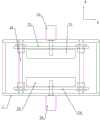
图5为第二封口组件的结构示意图;5 is a schematic structural diagram of a second sealing assembly;
图6为支撑组件与推料组件的配合结构示意图;6 is a schematic diagram of the matching structure of the support assembly and the pusher assembly;
图7为薄膜上料组件、动力源组件、第一封口组件和切刀组件的结构示意图。FIG. 7 is a schematic structural diagram of a film feeding assembly, a power source assembly, a first sealing assembly and a cutter assembly.
具体实施方式Detailed ways
如图1-图7所示,一种制药包装设备,包括机架1,机架1上沿横向依次设有薄膜上料组件2、动力源组件3、第一封口组件4和切刀组件5,薄膜上料组件包括安装在机架1上的上料辊21、传送辊22和涨紧辊23,传送辊22位于上料辊21和涨紧辊23之间,涨紧辊23靠近动力源组件设置,动力源组件包括相对设置的上驱动辊31和下驱动辊32,上驱动辊31位于下驱动辊32上方,上驱动辊31和下驱动辊32沿纵向转动设置在机架1上,第一封口组件包括相对设置的上热封辊41和下热封辊42,上热封辊41位于下热封辊42上方,上热封辊41和下热封辊42沿纵向转动设置在机架1上,上热封辊41和下热封辊42内分别设有加热管,加热管通电后可发热,两者抵触配合可对薄膜进行热封操作,切刀组件包括相对设置的上切刀辊51和上切刀辊52,上切刀辊51位于上切刀辊52上方,上切刀辊51和下切刀辊52沿纵向转动设置在机架1上,上切刀辊51和上切刀辊52抵触配合可切断包装袋,机架1由上至下依次设有漏斗6、第二封口组件7和吸盘组件8,第二封口组件包括相对设置的第一热封块71和第二热封块72,第一热封块71和第二热封块72沿纵向设置,第一热封块71和第二热封块72可沿横向滑移的设置在机架1上,机架1上设有驱动第一热封块71和第二热封块72相互靠近或远离的第二驱动组件,第一热封块71和第二热封块72内分别设有加热管,加热管通电后可发热,两者抵触配合可对薄膜进行热封操作,吸盘组件包括沿横向设置的第一吸盘81和第二吸盘82,第一吸盘81和第二吸盘82之间构成沿竖直方向设置的开袋通道11,机架1上设有驱动第一吸盘81和第二吸盘82相向或相背伸缩移动的第一驱动组件,第一吸盘81和第二吸盘82分别至少设置有一个,第一驱动组件包括固定设置在机架1上的第一气缸83和第二气缸84,第一气缸83的伸缩杆和第二气缸84的伸缩杆分别沿横向设置,第一吸盘81安装在第一气缸83的伸缩杆上,当第一吸盘81设置多个时,可由一个第一气缸83带动,也可由多个第一气缸83带动,第二吸盘82安装在第二气缸84的伸缩杆上,当第二吸盘82设置多个时,可由一个第二气缸84带动,也可由多个第二气缸84带动,机架1上还设有可将包装袋传输至开袋通道11处的传输组件10,机架1在开袋通道11的下方还设有用于支撑包装袋的支撑组件A。其中竖直方向为附图1和附图4中的D方向,横向为附图1和附图5中的E方向,纵向为附图4和附图5中的F方向。As shown in Figures 1-7, a pharmaceutical packaging equipment includes a frame 1, and the frame 1 is provided with a film feeding assembly 2, a
在本实施例中,漏斗6的下端设有出料口61,机架1上设有用于通断出料口61的挡板9,挡板包括相对设置的第一挡板91和第二挡板92,第一挡板91和第二挡板92左右对称铰接设置在出料口41处,机架1上设有驱动第一挡板91和第二挡板92摆动的驱动件,第一挡板91的铰接轴911和第二挡板92的铰接轴921分别沿纵向设置,第一挡板51和第二挡板52由驱动件驱动同时向下摆动时,不仅可打开出料口61,可将袋口的两侧同时撑开。In this embodiment, the lower end of the
在本实施例中,传输组件10包括转动设置在机架1上的转动座101,转动座101由电机和传动轴带动并转动设置在机架1上,转动座101上设有输送气缸102,输送气缸102的伸缩杆上连接有第三吸盘103。In this embodiment, the
在本实施例中,支撑组件A包括支撑气缸A1和支撑座A2,支撑气缸A1固定设置在机架1上,支撑气缸A1的伸缩杆沿竖直方向设置,支撑气缸A1的伸缩杆的端部与支撑座A2固定连接。In this embodiment, the support assembly A includes a support cylinder A1 and a support base A2, the support cylinder A1 is fixedly arranged on the frame 1, the telescopic rod of the support cylinder A1 is arranged in the vertical direction, and the end of the telescopic rod of the support cylinder A1 It is fixedly connected with the support base A2.
在本实施例中,机架1上还设有下料斜面12,下料斜面12的下端处设有收纳盒B,机架1在对应下料斜面12的上端处设有推料组件C,推料组件C包括推料气缸C1和推板C2,推料气缸C1的伸缩杆沿横向设置,推料气缸C1固定设置在机架1上,推料气缸C1的伸缩杆的端部与推板C2固定连接。支撑座A2向下移动至下料斜面12的上端位置,停止移动,此时推料气缸C1带动推板C2横向移动,可将支撑座A2上的包装袋推至下料斜面12处,包装袋可沿下料斜面12滑落至收纳盒B内,完成下料操作。In the present embodiment, the rack 1 is further provided with a blanking
在本实施例中,驱动件包括第三气缸93和第四气缸94,第三气缸93和第四气缸94的端部分别铰接设置在机架1上,第三气缸93的伸缩杆通过第一连杆95与第一挡板91连接,第四气缸94的伸缩杆通过第二连杆96与第二挡板92连接,第一连杆95一端铰接在第三气缸93的伸缩杆上,另一端固定或一体设置在第一挡板91的铰接轴911上,第二连杆96一端铰接在第四气缸94的伸缩杆上,另一端固定或一体设置在第二挡板92的铰接轴921上。当然也可以采用电机作为驱动件,直接驱动第一挡板91和第二挡板92摆动。当然也可以通过一个气缸同时驱动第一挡板91和第二挡板92摆动,从而实现出料口的通断。In this embodiment, the driving member includes a
在本实施例中,机架1上沿横向固定或一体设置有导轨13,第一热封块71通过第一安装座73设置在机架1上,第一热封块71固定设置在第一安装座73上,第二热封块72通过第二安装座74设置在机架1上,第二热封块72固定设置在第二安装座74上,第一安装座73和第二安装座74分别与导轨12导向滑移配合,第二驱动组件包括固定设置在机架1上的第五气缸75和第六气缸76,第五气缸75和第六气缸76的伸缩杆分别沿纵向设置,第五气缸75的伸缩杆与第一安装座73连接,第六气缸76的伸缩杆与第二安装座74连接。In this embodiment, the guide rail 13 is fixed or integrally provided on the rack 1 in the lateral direction, the first
以上实施例,只是本实用新型优选地具体实施例的一种,本领域技术人员在本实用新型技术方案范围内进行的通常变化和替换都包含在本实用新型的保护范围内。The above embodiment is only one of the preferred specific embodiments of the present invention, and the usual changes and substitutions made by those skilled in the art within the scope of the technical solution of the present invention are included in the protection scope of the present invention.
Claims (10)
Priority Applications (1)
| Application Number | Priority Date | Filing Date | Title |
|---|---|---|---|
| CN201922095644.4UCN211055423U (en) | 2019-11-28 | 2019-11-28 | Pharmaceutical packaging equipment |
Applications Claiming Priority (1)
| Application Number | Priority Date | Filing Date | Title |
|---|---|---|---|
| CN201922095644.4UCN211055423U (en) | 2019-11-28 | 2019-11-28 | Pharmaceutical packaging equipment |
Publications (1)
| Publication Number | Publication Date |
|---|---|
| CN211055423Utrue CN211055423U (en) | 2020-07-21 |
Family
ID=71592359
Family Applications (1)
| Application Number | Title | Priority Date | Filing Date |
|---|---|---|---|
| CN201922095644.4UExpired - Fee RelatedCN211055423U (en) | 2019-11-28 | 2019-11-28 | Pharmaceutical packaging equipment |
Country Status (1)
| Country | Link |
|---|---|
| CN (1) | CN211055423U (en) |
Cited By (5)
| Publication number | Priority date | Publication date | Assignee | Title |
|---|---|---|---|---|
| CN111977034A (en)* | 2020-08-05 | 2020-11-24 | 合肥诚唯信包装科技有限公司 | Bag opening and filling mechanism and using method thereof |
| CN114132547A (en)* | 2021-11-08 | 2022-03-04 | 温州职业技术学院 | A fast automatic aluminum-plastic blister packaging machine for pharmaceutical use |
| CN116062268A (en)* | 2023-03-06 | 2023-05-05 | 成都圣恩生物科技股份有限公司 | Packaging bag unsealing device, unsealing method and stir-frying device |
| CN116812260A (en)* | 2023-08-09 | 2023-09-29 | 安徽省正大源饲料集团有限公司 | Quantitative packaging equipment for feed pellet processing |
| CN117429696A (en)* | 2023-12-18 | 2024-01-23 | 黑龙江火龙神农业生物技术有限责任公司 | Filling process for fertilizer processing with convenient positioning of pocket openings |
- 2019
- 2019-11-28CNCN201922095644.4Upatent/CN211055423U/ennot_activeExpired - Fee Related
Cited By (6)
| Publication number | Priority date | Publication date | Assignee | Title |
|---|---|---|---|---|
| CN111977034A (en)* | 2020-08-05 | 2020-11-24 | 合肥诚唯信包装科技有限公司 | Bag opening and filling mechanism and using method thereof |
| CN114132547A (en)* | 2021-11-08 | 2022-03-04 | 温州职业技术学院 | A fast automatic aluminum-plastic blister packaging machine for pharmaceutical use |
| CN116062268A (en)* | 2023-03-06 | 2023-05-05 | 成都圣恩生物科技股份有限公司 | Packaging bag unsealing device, unsealing method and stir-frying device |
| CN116812260A (en)* | 2023-08-09 | 2023-09-29 | 安徽省正大源饲料集团有限公司 | Quantitative packaging equipment for feed pellet processing |
| CN117429696A (en)* | 2023-12-18 | 2024-01-23 | 黑龙江火龙神农业生物技术有限责任公司 | Filling process for fertilizer processing with convenient positioning of pocket openings |
| CN117429696B (en)* | 2023-12-18 | 2024-04-02 | 黑龙江火龙神农业生物技术有限责任公司 | Filling process for fertilizer processing with convenient positioning of pocket openings |
Similar Documents
| Publication | Publication Date | Title |
|---|---|---|
| CN211055423U (en) | Pharmaceutical packaging equipment | |
| CN111319823A (en) | Side pushing type bag-in-bag packaging machine | |
| CN101837843B (en) | Automatic packaging unit for vacuum packaging of inner bag and outer bag | |
| CN203032983U (en) | Universal type automatic block material packing device | |
| CN206502056U (en) | Clovershrub corner angle digital-control packing machine | |
| CN201559815U (en) | Film inner bag making bag filling device for automatic vacuum packaging of inner and outer bags | |
| CN103193001A (en) | An aseptic filling machine | |
| CN109018537A (en) | A kind of horizontal sack filling machine | |
| CN106347765B (en) | A kind of automatic medicine packing device | |
| CN110155392B (en) | Material receiving and packaging mechanism of automatic ribbon packaging machine | |
| CN207292634U (en) | A kind of self-styled bag package machine | |
| CN106697358B (en) | A packaging device for packaging blood bags before transportation | |
| CN211108298U (en) | Packagine machine opens bag feed mechanism | |
| CN209209098U (en) | Three bandings vacuumize online packing machine for powder | |
| CN207360655U (en) | A kind of vacuum packaging equipment | |
| CN216292403U (en) | An automatic bag filling machine | |
| CN112744397B (en) | High-speed bag filling and sealing machine | |
| CN220996828U (en) | Full-automatic powder packagine machine | |
| CN109552682A (en) | Three bandings vacuumize online packing machine for powder and its working method | |
| CN109264038A (en) | A kind of packing machine | |
| CN219728747U (en) | Automatic bagging and sealing machine | |
| CN215205635U (en) | Horizontal bag conveying mechanism of automatic bagging equipment | |
| CN110937172B (en) | A fully automatic packaging machine | |
| CN117342070B (en) | Disposable tableware batched bagging and tearing glue packaging machine | |
| CN115649561B (en) | Automatic tremella continuous packaging machine |
Legal Events
| Date | Code | Title | Description |
|---|---|---|---|
| GR01 | Patent grant | ||
| GR01 | Patent grant | ||
| CF01 | Termination of patent right due to non-payment of annual fee | Granted publication date:20200721 Termination date:20211128 | |
| CF01 | Termination of patent right due to non-payment of annual fee |