CN211049720U - Heart valve prosthesis and system - Google Patents
Heart valve prosthesis and systemDownload PDFInfo
- Publication number
- CN211049720U CN211049720UCN201920819376.3UCN201920819376UCN211049720UCN 211049720 UCN211049720 UCN 211049720UCN 201920819376 UCN201920819376 UCN 201920819376UCN 211049720 UCN211049720 UCN 211049720U
- Authority
- CN
- China
- Prior art keywords
- heart valve
- valve prosthesis
- tube
- protection tube
- tether
- Prior art date
- Legal status (The legal status is an assumption and is not a legal conclusion. Google has not performed a legal analysis and makes no representation as to the accuracy of the status listed.)
- Active
Links
Images


Classifications
- A—HUMAN NECESSITIES
- A61—MEDICAL OR VETERINARY SCIENCE; HYGIENE
- A61F—FILTERS IMPLANTABLE INTO BLOOD VESSELS; PROSTHESES; DEVICES PROVIDING PATENCY TO, OR PREVENTING COLLAPSING OF, TUBULAR STRUCTURES OF THE BODY, e.g. STENTS; ORTHOPAEDIC, NURSING OR CONTRACEPTIVE DEVICES; FOMENTATION; TREATMENT OR PROTECTION OF EYES OR EARS; BANDAGES, DRESSINGS OR ABSORBENT PADS; FIRST-AID KITS
- A61F2/00—Filters implantable into blood vessels; Prostheses, i.e. artificial substitutes or replacements for parts of the body; Appliances for connecting them with the body; Devices providing patency to, or preventing collapsing of, tubular structures of the body, e.g. stents
- A61F2/02—Prostheses implantable into the body
- A61F2/24—Heart valves ; Vascular valves, e.g. venous valves; Heart implants, e.g. passive devices for improving the function of the native valve or the heart muscle; Transmyocardial revascularisation [TMR] devices; Valves implantable in the body
Landscapes
- Health & Medical Sciences (AREA)
- Cardiology (AREA)
- Oral & Maxillofacial Surgery (AREA)
- Transplantation (AREA)
- Engineering & Computer Science (AREA)
- Biomedical Technology (AREA)
- Heart & Thoracic Surgery (AREA)
- Vascular Medicine (AREA)
- Life Sciences & Earth Sciences (AREA)
- Animal Behavior & Ethology (AREA)
- General Health & Medical Sciences (AREA)
- Public Health (AREA)
- Veterinary Medicine (AREA)
- Prostheses (AREA)
Abstract
Description
Translated fromChinese技术领域technical field
本实用新型涉及植入式医疗器械领域,特别是涉及一种心脏瓣膜假体及心系统。The utility model relates to the field of implantable medical devices, in particular to a heart valve prosthesis and a heart system.
背景技术Background technique
人体的心脏分为左心房、左心室和右心房、右心室四个心腔,两个心房分别和两个心室相连,两个心室和两个大动脉相连。在心房和心室之间以及心室和大动脉之间存在共四个心脏瓣膜,心脏瓣膜起到单向阀门的作用,使血流单方向运动。四个心脏瓣膜分别为二尖瓣、三尖瓣、主动脉瓣和肺动脉瓣。这些心脏瓣膜如果出现了病变,就会影响血流的运动,从而造成心脏功能异常,最终导致心功能衰竭。The human heart is divided into four chambers: the left atrium, the left ventricle, the right atrium, and the right ventricle. There are a total of four heart valves between the atrium and the ventricle and between the ventricle and the aorta. The heart valve acts as a one-way valve, allowing the blood flow to move in one direction. The four heart valves are the mitral, tricuspid, aortic, and pulmonary valves. If these heart valves are damaged, it will affect the movement of blood flow, resulting in abnormal heart function and eventually heart failure.
目前,心脏瓣膜疾病已经成为较为普遍的心脏疾患。随着人口老龄化加重,老年性瓣膜病以及冠心病心肌梗死后引起的瓣膜病变也越来越常见。这些心脏瓣膜病变不但影响生活质量,同时给家庭和社会带来沉重的负担和压力,严重的还危害生命安全。At present, heart valve disease has become a relatively common heart disease. With the aging of the population, senile valvular disease and valvular disease caused by coronary heart disease and myocardial infarction are becoming more and more common. These heart valve diseases not only affect the quality of life, but also bring heavy burden and pressure to the family and society, and seriously endanger life safety.
目前治疗心脏瓣膜病的外科手术治疗主要分两种方法:1)瓣膜成形术,即对损害的瓣膜进行修理;2)瓣膜置换术,用人工机械瓣或生物瓣进行替换。瓣膜成形术通常用于病变轻微的二尖瓣或三尖瓣,而对于严重的心脏瓣膜病变,特别是风湿性心脏瓣膜病,多选择瓣膜置换术。瓣膜置换术一般借助输送器械,通过介入、微创的方法植入心脏瓣膜假体。在输送过程中,输送器械与心脏瓣膜假体可拆卸连接,心脏瓣膜假体植入病变部位后,心脏瓣膜假体与输送器械断开连接,并通过系绳将心脏瓣膜假体与心脏组织相连,以防止心脏瓣膜假体移位。然而,心脏瓣膜假体与输送器械连接一般是柔性连接或刚性连接,当采用柔性连接时,在将心脏瓣膜假体推出鞘管时没有任何支撑力,需要借助另外的器械,植入操作较为麻烦;当采用刚性连接时,受限于心脏瓣膜假体与输送器械的连接方式,心脏瓣膜假体在植入后,系绳容易因摩擦而断裂,这可能会导致心脏瓣膜移位,从而难以达到治疗效果。There are currently two main surgical treatments for valvular heart disease: 1) valvuloplasty, which repairs the damaged valve; 2) valve replacement, which is replaced with an artificial mechanical valve or a biological valve. Valvuloplasty is usually used for mildly diseased mitral or tricuspid valves, while for severe heart valve disease, especially rheumatic heart valve disease, valve replacement is more of a choice. Valve replacement surgery generally uses delivery devices to implant heart valve prostheses through interventional and minimally invasive methods. During the delivery process, the delivery device is detachably connected to the heart valve prosthesis. After the heart valve prosthesis is implanted into the diseased site, the heart valve prosthesis is disconnected from the delivery device, and the heart valve prosthesis is connected to the heart tissue through a tether. , to prevent displacement of the heart valve prosthesis. However, the connection between the heart valve prosthesis and the delivery device is generally a flexible connection or a rigid connection. When a flexible connection is used, there is no supporting force when the heart valve prosthesis is pushed out of the sheath, and another device is required, which makes the implantation operation more troublesome. ; When rigid connection is used, limited by the connection between the heart valve prosthesis and the delivery device, after the heart valve prosthesis is implanted, the tether is easily broken due to friction, which may lead to the displacement of the heart valve, making it difficult to achieve treatment effect.
实用新型内容Utility model content
基于此,有必要提供一种方便植入且不易移位的心脏瓣膜假体。Based on this, it is necessary to provide a heart valve prosthesis that is easy to implant and not easily displaced.
一种心脏瓣膜假体,包括支架、连接件和系绳,所述连接件包括连接盖及与所述连接盖相连的连接座,所述连接盖与所述支架相连,所述连接座上开设有螺孔,所述心脏瓣膜假体还包括中空的保护管,所述保护管至少部分收容于所述螺孔中且所述保护管的外壁与所述螺孔的内壁形成间隙,所述保护管具有第一开口端以及与所述第一开口端相对的第二开口端,所述系绳穿设所述保护管,且所述系绳的一端收容于所述连接盖或所述连接座内部。A heart valve prosthesis includes a support, a connecting piece and a tether, the connecting piece includes a connecting cover and a connecting seat connected with the connecting cover, the connecting cover is connected with the support, and the connecting seat is provided with There are screw holes, the heart valve prosthesis also includes a hollow protection tube, the protection tube is at least partially accommodated in the screw hole, and the outer wall of the protection tube and the inner wall of the screw hole form a gap, and the protection tube is at least partially accommodated in the screw hole. The tube has a first open end and a second open end opposite to the first open end, the tether passes through the protection tube, and one end of the tether is accommodated in the connection cover or the connection seat internal.
在其中一个实施方式中,所述保护管与所述连接座为一体式结构;或者,所述保护管与所述连接座为非一体式结构,且所述保护管与所述连接座固定连接。In one of the embodiments, the protection tube and the connection seat are of an integrated structure; or, the protection tube and the connection seat are of a non-integrated structure, and the protection tube and the connection seat are fixedly connected .
在其中一个实施方式中,所述系绳上设置有抵持部,所述保护管的第一开口端的端面与所述连接座的内壁抵持,所述保护管的第二开口端的端面与所述抵持部抵持。In one embodiment, an abutting portion is provided on the tether, the end face of the first open end of the protection tube abuts against the inner wall of the connecting seat, and the end face of the second open end of the protection tube is in contact with the inner wall of the connection seat. The said resisting part resists.
在其中一个实施方式中,所述保护管包覆于所述系绳上,且所述保护管与所述系绳固定相连。In one embodiment, the protection tube is wrapped on the tether, and the protection tube is fixedly connected to the tether.
在其中一个实施方式中,所述保护管部分收容于所述螺孔中,且所述保护管的一端伸出至所述连接座的外部。In one embodiment, the protection tube is partially accommodated in the screw hole, and one end of the protection tube protrudes to the outside of the connection seat.
在其中一个实施方式中,所述支架包括瓣叶支架和多个连杆,所述瓣叶支架具有第一端及与所述第一端相对的第二端,每个所述连杆包括第一杆部、第二杆部及接头,所述第二杆部与所述第一杆部连接,所述接头与所述第二杆部的远离所述第一杆部的一端连接,所述第一杆部的远离所述第二杆部的一端与所述瓣叶支架的第二端连接,所述接头与所述连接盖连接,所述第二杆部与所述瓣叶支架的纵向中心轴线的夹角为40°~60°。In one embodiment, the stent includes a leaflet support and a plurality of links, the leaflet support has a first end and a second end opposite the first end, each of the links includes a first end a rod part, a second rod part and a joint, the second rod part is connected with the first rod part, the joint is connected with the end of the second rod part away from the first rod part, the One end of the first rod part away from the second rod part is connected with the second end of the leaflet support, the joint is connected with the connection cover, and the second rod part is connected to the longitudinal direction of the leaflet support The included angle of the central axis is 40° to 60°.
在其中一个实施方式中,所述连接盖具有内腔,且所述连接盖上开设多个间隔设置且均与所述内腔连通的限位孔,所述多个接头分别穿过所述多个限位孔中,且多个所述接头分别遮挡多个所述限位孔,以阻止所述接头从所述限位孔内脱出。In one embodiment, the connection cover has an inner cavity, and the connection cover is provided with a plurality of spaced limiting holes which are all communicated with the inner cavity, and the plurality of joints pass through the plurality of joints respectively. The plurality of limit holes are respectively blocked by the plurality of joints, so as to prevent the joints from coming out of the limit holes.
在其中一个实施方式中,所述连接座包括连接部及与所述连接部相连的插接部,所述连接盖套设于所述插接部上,且所述连接盖与所述连接部抵接。In one embodiment, the connection base includes a connection part and a plug-in part connected to the connection part, the connection cover is sleeved on the plug-in part, and the connection cover is connected to the connection part. Abut.
在其中一个实施方式中,所述插接部的远离所述连接部的一端形成有收容槽,所述保护管包括管体及与所述管体连接的固定部,所述固定部收容于所述收容槽中,且所述管体自所述收容槽沿所述连接部的轴向延伸。In one embodiment, a receiving groove is formed at one end of the plug-in portion away from the connecting portion, the protection tube includes a tube body and a fixing portion connected to the tube body, and the fixing portion is accommodated in the receiving portion. in the receiving groove, and the pipe body extends from the receiving groove along the axial direction of the connecting portion.
一种心脏瓣膜假体系统,包括输送器械及上述心脏瓣膜假体,所述输送器械包括输送鞘管及可滑动地收容于所述输送鞘管中的推送管,所述推送管的一端设有外螺纹,所述外螺纹与所述连接座上的所述螺孔配合使所述推送管与所述心脏瓣膜假体可拆卸连接。A heart valve prosthesis system, comprising a delivery device and the above-mentioned heart valve prosthesis, the delivery device includes a delivery sheath and a push tube slidably accommodated in the delivery sheath, one end of the push tube is provided with an external thread, the external thread cooperates with the screw hole on the connection seat to detachably connect the push tube and the heart valve prosthesis.
在其中一个实施方式中,所述螺孔的轴向长度大于或等于所述外螺纹的轴向长度。In one of the embodiments, the axial length of the screw hole is greater than or equal to the axial length of the external thread.
在输送过程中,将输送器械的推送管与连接座的螺孔螺纹连接,通过推动推送管将心脏瓣膜假体推出输送鞘管,无需借助额外的器械推送心脏瓣膜假体,植入较为方便;并且,系绳穿设保护管,避免了系绳与螺孔内壁直接接触,有效防止系绳断裂,从而有利于避免心脏瓣膜假体移位。During the delivery process, the push tube of the delivery device is threadedly connected to the screw hole of the connection seat, and the heart valve prosthesis is pushed out of the delivery sheath by pushing the push tube, without the need for additional instruments to push the heart valve prosthesis, and the implantation is more convenient; In addition, the tether is provided with a protective tube, which avoids direct contact between the tether and the inner wall of the screw hole, effectively prevents the tether from breaking, and thus helps to avoid displacement of the heart valve prosthesis.
附图说明Description of drawings
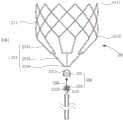
图1为一实施方式的心脏瓣膜假体系统的结构示意图;1 is a schematic structural diagram of a heart valve prosthesis system according to an embodiment;
图2为图1所示的心脏瓣膜假体系统的省略输送鞘管后的立体分解图;FIG. 2 is an exploded perspective view of the heart valve prosthesis system shown in FIG. 1 after the delivery sheath is omitted;
图3为图1所示的心脏瓣膜假体系统的省略输送鞘管后的结构示意图;3 is a schematic structural diagram of the heart valve prosthesis system shown in FIG. 1 after the delivery sheath is omitted;
图4为图1所示的心脏瓣膜假体系统的连接件与推送管的立体分解图;4 is an exploded perspective view of a connector and a push tube of the heart valve prosthesis system shown in FIG. 1;
图5为图1所示的心脏瓣膜假体系统的连接件的结构示意图;5 is a schematic structural diagram of a connector of the heart valve prosthesis system shown in FIG. 1;
图6为图1所示的心脏瓣膜假体系统的连接件与推送管连接状态示意图;6 is a schematic diagram of the connection state between the connector of the heart valve prosthesis system shown in FIG. 1 and the push tube;
图7为另一实施方式的心脏瓣膜假体系统的连接件、保护管与推送管的立体分解图;7 is an exploded perspective view of a connector, a protection tube and a push tube of a heart valve prosthesis system according to another embodiment;
图8为图7的剖面图;Fig. 8 is the sectional view of Fig. 7;
图9为图1所示的心脏瓣膜假体系统的推送管与心脏瓣膜假体连接状态示意图;9 is a schematic diagram of the connection state between the push tube of the heart valve prosthesis system shown in FIG. 1 and the heart valve prosthesis;
图10为一实施方式的心脏瓣膜假体植入心脏病变部位后的状态示意图;FIG. 10 is a schematic diagram of the state of the heart valve prosthesis after implantation in a heart disease site according to an embodiment;
图11为另一实施方式的连接件、保护管与系数的连接状态示意图。FIG. 11 is a schematic diagram of the connection state of the connector, the protection tube and the coefficient according to another embodiment.
具体实施方式Detailed ways
为了便于理解本实用新型,下面将参照相关附图对本实用新型进行更全面的描述。附图中给出了本实用新型的较佳的实施例。但是,本实用新型可以以许多不同的形式来实现,并不限于本文所描述的实施例。相反地,提供这些实施例的目的是使对本实用新型的公开内容的理解更加透彻全面。In order to facilitate the understanding of the present utility model, the present utility model will be more fully described below with reference to the related drawings. The preferred embodiments of the present utility model are shown in the accompanying drawings. However, the present invention may be implemented in many different forms and is not limited to the embodiments described herein. Rather, these embodiments are provided so that a thorough and complete understanding of the present disclosure is provided.
除非另有定义,本文所使用的所有的技术和科学术语与属于本实用新型的技术领域的技术人员通常理解的含义相同。本文中在本实用新型的说明书中所使用的术语只是为了描述具体的实施例的目的,不是旨在于限制本实用新型。本文所使用的术语“及/或”包括一个或多个相关的所列项目的任意的和所有的组合。Unless otherwise defined, all technical and scientific terms used herein have the same meaning as commonly understood by one of ordinary skill in the technical field to which the present invention belongs. The terms used in the description of the present invention herein are only for the purpose of describing specific embodiments, and are not intended to limit the present invention. As used herein, the term "and/or" includes any and all combinations of one or more of the associated listed items.
请参阅图1,一实施方式的心脏瓣膜假体系统100,包括心脏瓣膜假体20和输送器械40。输送器械40与心脏瓣膜假体20可拆卸连接,借助输送器械40将心脏瓣膜假体20输送至病变部位后,断开输送器械40与心脏瓣膜假体20的连接,并将输送器械40从生物体体内撤回,完成手术。Referring to FIG. 1 , an embodiment of a heart
请一并参阅图2和图3,心脏瓣膜假体20包括支架210、连接件230、系绳250和保护管270。Please refer to FIG. 2 and FIG. 3 together, the
支架210包括瓣叶支架211和多个连杆213。本实施方式中,瓣叶支架211大致为由网状金属或网状聚合物等围成的呈管腔结构。如图3所示,瓣叶支架211具有第一端2111及与第一端2111相对的第二端2113。每个连杆213的一端与瓣叶支架211的第二端2113固定连接。可以理解,在其他实施方式中,瓣叶支架211的结构不限于图2和图3所示的方式,瓣叶支架211可以为满足能够压缩而装载于输送器械40中,且在释放后能够提供足够的径向力的要求的其他方式。例如,在一实施方式中,瓣叶支架211为由多个环状波圈通过连接件轴向相连形成的管腔结构。The
可以理解,瓣叶支架211还用于支撑和固定瓣叶(图未示),以使心脏瓣膜假体20能够起到单向阀门的作用,获得天然心脏瓣膜具有的功能。It can be understood that the
请再次参阅图3,在一实施例中,每个连杆213包括第一杆部2131、第二杆部2133和接头2135。第一杆部2131的一端与瓣叶支架211的第二端2113固定连接,第二杆部2133的远离第一杆部2131的一端与接头2135固定连接。第一杆部2131、第二杆部2133和接头2135一体成型形成连杆213,或者,第一杆部2131、第二杆部2133和接头2135通过焊接、胶粘等方式固定连接。Referring to FIG. 3 again, in one embodiment, each link 213 includes a
本实施方式中,第一杆部2131大致为一端开口的U形杆,并且,U形杆的开口端的宽度大于封闭端的宽度。U形杆的两个开口端与瓣叶支架211的第二端2113固定连接。第二杆部2133大致为直杆,第二杆部2133的一端连接于U形杆的封闭端的中部。接头2135大致为杆状,且接头2135的延伸方向与第二杆部2133垂直。沿接头2135的延伸方向,接头2135的尺寸大于第二杆部2133的尺寸。In this embodiment, the
可以理解,在其他实施方式中,第一杆部2131的形状不限于一端开口的U形杆,第二杆部21的形状也不限于直杆状,接头2135的形状亦不限于杆状,其他满足连杆213能够与瓣叶支架211和连接件230连接,且方便将瓣叶支架211收入输送器械40中的形状均可。例如,在其他实施方式中,第一杆部2131为V形杆,第二杆部2133为异形杆,接头2135为球形、圆片形等。It can be understood that in other embodiments, the shape of the
在本实施方式中,瓣叶支架211和多个连杆213一体成型形成支架210。例如,通过金属管材一体切割而成形成支架210。在另外的实施方式中,由多个零配件组装构成支架210。一体成型相对多个零配件组装,具有压缩后径向尺寸小、容易入鞘的优点,同时支架210的各部分取消焊接或拼接结构,有利于提高支架210的抗疲劳性能。In this embodiment, the
连接件230用于连接支架210和输送器械40。请再次参阅图2,连接件230包括连接盖231及与连接盖231相连的连接座233。请回到参阅图3,连接盖231具有内腔2311。请一并参阅图4,连接盖231上开设多个间隔设置的限位孔2313,每个限位孔2313均与内腔2311连通。多个连杆213的多个接头2135分别穿过多个限位孔2313中,且多个接头2135分别遮挡多个限位孔2313,以阻止接头2135从限位孔2313内脱出,从而使多个接头2135收容于连接盖231的内腔2311中。可以理解,限位孔2313的数量与接头2135的数量相等。The
如图4所示,连接座233包括连接部2331及与连接部2331相连的插接部2333,连接盖231套设于插接部2333上,且连接盖231与连接部2331抵接且固定相连。连接盖231与连接座233固定相连的状态如图5所示。连接部2331与插接部2333固定连接,可以通过本领域技术人员掌握的连接方式实现固定连接,例如,焊接。或者,连接部2331与插接部2333一体成型。请对照图6,连接座233的中部开设有螺孔2335,螺孔2335沿连接座233的轴向延伸,并从连接部2331延伸至插接部2333。As shown in FIG. 4 , the connecting
连接盖231和连接部2331固定连接,进一步将连杆213的接头2135限制在连接件230的内部,实现连接件230与支架210的可靠连接。在一实施方式中,当心脏瓣膜假体20处于打开状态下,第二杆部2133与瓣叶支架211的轴线的夹角为α,α为40°~60°。α为40°~60°时,能够较好地控制心脏瓣膜假体20的入鞘阻力,以方便装载。同时,能够保证瓣叶支架211具有一定的支撑强度,以在植入后瓣叶支架211能够可靠地抵接心脏组织。The connecting
连杆213的接头2135限制在连接件230的内部,但接头2135并没有与连接件230固定连接,当任意一个连杆213的受到较大的局部应力时,连杆213会围绕连接接盖231的几何中心旋转,从而自适应应力变化,提高心脏瓣膜假体100的抗疲劳性能。The joint 2135 of the connecting
保护管270为中空管体。请参阅图3,保护管270至少部分收容于螺孔2335中。保护管270的外壁与螺孔2335的内壁形成间隙(图未示)。保护管270的延伸方向与螺孔2335的延伸方向相同。请一并参阅图6,保护管270具有第一开口端271以及与第一开口端271相对设置的第二开口端273。本实施方式中,保护管270的一端位于螺孔2335的内部,另一端从螺孔2335中伸出而位于连接部2331的外部。或者,在另一实施方式中,保护管270的一端与螺孔2335的一端平齐,另一端与螺孔2335的另一端平齐。The
保护管270与连接座233可以为一体式结构,也可以为非一体式结构,并且通过本领域技术人员掌握的连接方法,将保护管270与连接座233固定相连。The
请参阅图6,当保护管270与连接座233为一体式结构时,保护管270为自插接部2333的端部的内壁向连接部2331轴向延伸的中空直管。当保护管270与连接座233为非一体式结构时,保护管270亦为自插接部2333的端部的内壁向连接部2331轴向延伸的中空直管,并且,保护管270的第一开口端271的端面与插接部2333的端部的内壁固定相连。Referring to FIG. 6 , when the
在一实施方式中,如图7所示,保护管270包括管体275和固定部277,管体275为中空的管腔结构,固定部277为中空的圆柱体,固定部277与管体275的一端连接,且固定部277的内腔与管体275的内腔连通。固定部277的远离管体275的一端为保护管270的第一开口端271,管体275的远离固定部277的一端为保护管270的第二开口端273。固定部277的外径大于管体275的外径。请一并参阅图7和图8,插接部2333的远离连接部2331的一端形成有收容槽2337,且收容槽2337的槽底形成有通孔2339(图8未示)。管体275穿过通孔2339,且固定部277收容于收容槽2337中,进一步,通过焊接、胶粘等方式将固定部277固定于收容槽2337中,从而实现保护管270与插接部2333固定连接。In one embodiment, as shown in FIG. 7 , the
包括管体275和固定部277的保护管270有利于装配,使保护管70与连接座233固定连接较为方便,且连接较为可靠。The
系绳250用于避免心脏瓣膜假体20移位。系绳250穿设保护管270。请参阅图9,系绳250的一端收容于连接盖231或连接座233内部,另一端从保护管270从伸出。从保护管270中伸出的一端与心脏组织固定。例如,从保护管270中伸出的一端穿过心尖并固定。请再次参阅图8,系绳250的一端形成有阻挡部252,设置阻挡部252以使系绳250的一端与连接盖231或连接座233保持相对固定。具体地,本实施方式中,阻挡部252呈球状,且阻挡部252的直径大于固定部277的内径,防止阻挡部252自保护管270中脱落。Tether 250 is used to avoid displacement of
可以理解,在其他实施方式中,系绳250的一端可以伸入连接盖231中,且阻挡部252被卡住而防止阻挡部252自连接盖231中脱落。例如,系绳250的一端从连接盖231的任一限位孔2313中伸出连接盖231,并且阻挡部252的至少一维尺寸大于限位孔2313的尺寸使得阻挡部252被阻挡在连接盖231的外部。It can be understood that, in other embodiments, one end of the
可以理解,在其他实施方式中,阻挡部252不限于球状,在满足阻挡部252被阻挡的前提下,可以为任意形状。例如,阻挡部252为片状、杆状等等。或者,阻挡部252也可以为系绳250的一端打结形成的结构。It can be understood that, in other embodiments, the blocking
系绳250的材料包括但不限于金属和高分子材料。在一实施方式中,系绳250的材料为聚乙烯。Materials for
请再次参阅图1,输送器械40包括输送鞘管41及推送管43。推送管43的一端设有外螺纹431。将推送管43的设有外螺纹431的一端伸入连接座233中的保护管270的外壁与螺孔2335的内壁形成的间隙中,外螺纹431与螺孔2335的内螺纹配合,使推送管43与心脏瓣膜假体20可拆卸连接,两者连接的状态如图9所示。推送管43可滑动地收容于输送鞘管41中,通过使推送管43往相反的两个方向沿输送鞘管41轴向滑动,实现将心脏瓣膜假体20收入输送鞘管41内部或将心脏瓣膜假体20从输送鞘管41中推出。Please refer to FIG. 1 again, the
在一实施方式中,螺孔2335的轴向长度大于或等于外螺纹431的轴向长度。一方面,保证螺纹连接部位具有足够长度,以使推送管43与心脏瓣膜假体20可靠连接;另一方面,避免外螺纹431裸露在外,对人体组织造成损伤。其中,外螺纹431的轴向长度是指推送管43的设有外螺纹431的部分的轴向长度。In one embodiment, the axial length of the
推送管43由硬质材料或者软质材料组成。硬质材料为不锈钢等金属材料,软质材料为高分子材等。例如,在一实施方式中,推送管43为空心的不锈钢管。The
使用时,将推送管43与心脏瓣膜假体20通过螺纹连接,其中,心脏瓣膜假体20的系绳250的远离阻挡部252的一端伸入推送管43的内腔中,如图9所示。沿轴向拉动推送管43,使推送管43在输送鞘管41的内腔中轴向滑动,从而将心脏瓣膜假体20装载于输送鞘管41的内腔中。以植入二尖瓣心脏瓣膜假体为例进行说明,在心尖部位穿刺形成小缺口,然后通过输送鞘管41将心脏瓣膜假体20输送至病变部位后,推动推送管43,使推送管43在输送鞘管41的内腔中轴向滑动,滑动的方向与装载时的滑动方向相反,从而将心脏瓣膜假体20推出至输送鞘管41外,心脏瓣膜假体20自膨胀并定位于心脏瓣膜病变部位后,旋转推送管43,以断开推送管43与心脏瓣膜假体20的连接,并撤回推送管43和输送鞘管41。此时,如图10所示,系绳250的远离阻挡部252的一端位于心脏30的外部,将系绳250的远离阻挡部252的一端固定在心脏30的外部,瓣膜支架211的径向支撑力及系绳250的拉动作用使得心脏瓣膜假体20可靠地固定在二尖瓣位置。When in use, the
上述心脏瓣膜假体20采用刚性的连接件230与推送管43相连,并借助推送管43推送心脏瓣膜假体20,无需借助额外的器械推送心脏瓣膜假体20,植入较为方便。The above-mentioned
并且,在植入后,可能会出现系绳250与支架210的连接点与系绳250与心尖部位的连接点所确定的直线与心脏瓣膜假体20的纵向中心轴线不共线(两条线所形成的角度即不为0°,也不为180°)的情况,即系绳250与支架210的连接点与系绳250与心尖部位的连接点所确定的直线相对心脏瓣膜假体20的纵向中心轴线倾斜。如此,当省略保护管270时,系绳250与螺孔2335的内壁的螺纹直接接触、摩擦,容易断裂。尤其是在心脏不断地收缩和舒张运动中,系绳250与螺纹不断地摩擦,更容易断裂。上述心脏瓣膜假体20,由于系绳250穿设保护管270,避免了系绳250直接与螺孔2335内壁的螺纹直接接触、摩擦,有效防止系绳250断裂,从而有利于避免心脏瓣膜假体20移位。Also, after implantation, it may occur that the line determined by the connection point of the
当心脏瓣膜假体20释放后,若释放位置并非预期的位置,需要通过输送器械40将心脏瓣膜假体20收回至输送鞘管41中,重新定位并释放。具体操作如下:在系绳250的引导下,推送管43在输送鞘管41内滑动至靠近心脏瓣膜假体20后,旋转推送管43使推送管43重新与心脏瓣膜假体20螺纹连接以实现心脏瓣膜假体20的回收。然而,在此过程中,由于操作者在体外操作,在推送管43向靠近心脏瓣膜假体20移动的过程中,推送管43的外螺纹会很容易切断系绳250,导致器械失效。设置有保护管270,有利于避免系绳250与螺纹接触,有效防止系绳250断裂,避免在回收过程中器械失效。After the
在一实施方式中,保护管270与连接座233为一体式结构。可以理解,在其他实施方式中,两者为非一体式结构,而是通过焊接、胶粘等本领域技术人员掌握的连接方法固定相连。In one embodiment, the
在另一实施方式中,保护管270与连接座233即不是一体式结构,也不固定相连。保护管270套设于系绳250上,且保护管270至少部分收容于螺孔2335中,另一部分伸出连接座233或另一端的端部与连接座233的端部平齐。请参阅图11,此种情况下,系绳250上设有抵持部254,抵持部254与阻挡部252相对设置。保护管270的第一开口端271的端部与连接座233的内壁抵持,保护管270的第二开口端273的端部与抵持部抵持而被抵持部所阻挡,使得保护管270至少部分收容于螺孔2335的内部。In another embodiment, the
在另一实施方式中,保护管270包覆于系绳250上,且保护管270与系绳250固定相连。例如,保护管270为硅胶管,保护管270与系绳250直接固定相连,亦可较好地保护系绳250。In another embodiment, the
无论保护管270与连接座233为一体式结构,还是保护管270通过其他连接方式与连接座233固定相连,亦或是保护管270与连接座233不固定相连,而是被系绳250的抵持部所阻挡,保护管270的轴向长度大于或等于螺孔2335的轴向长度。当保护管270的轴向长度大于螺孔2335的轴向长度时,保护管270仅有部分收容于螺孔2335中,另一部分从连接座233中伸出而位于连接座233的外部。保护管270的轴向长度大于螺孔2335的轴向长度,一方面提供裕量,以在异常情况下(如保护管270异常缩短)也能保证有效隔离螺纹和系绳250;另一方面,在装载过程或在回收过程中,保护管270的伸出连接座233的部分能够提前校准推送管43与螺孔2335的同轴性,以引导推送管43快速地与螺孔2335对齐。Whether the
需要说明的是,上述以植入二尖瓣心脏瓣膜假体为例阐述了植入过程,但心脏瓣膜假体20不限于二尖瓣心脏瓣膜假体,还可以为三尖瓣心脏瓣膜假体、主动脉瓣心脏瓣膜假体或肺动脉瓣心脏瓣膜假体。上述实施方式中的心脏瓣膜假体20的支架210为自膨胀支架,在其他实施方式中,不限于自膨胀支架,例如,支架210可以为球囊扩张支架。It should be noted that the implantation process is described above by taking the implantation of a mitral valve prosthesis as an example, but the
以上所述实施例的各技术特征可以进行任意的组合,为使描述简洁,未对上述实施例中的各个技术特征所有可能的组合都进行描述,然而,只要这些技术特征的组合不存在矛盾,都应当认为是本说明书记载的范围。The technical features of the above-described embodiments can be combined arbitrarily. For the sake of brevity, all possible combinations of the technical features in the above-described embodiments are not described. However, as long as there is no contradiction between the combinations of these technical features, All should be regarded as the scope described in this specification.
以上所述实施例仅表达了本实用新型的几种实施方式,其描述较为具体和详细,但并不能因此而理解为对实用新型专利范围的限制。应当指出的是,对于本领域的普通技术人员来说,在不脱离本实用新型构思的前提下,还可以做出若干变形和改进,这些都属于本实用新型的保护范围。因此,本实用新型专利的保护范围应以所附权利要求为准。The above-mentioned embodiments only represent several embodiments of the present utility model, and the descriptions thereof are specific and detailed, but should not be construed as a limitation on the scope of the utility model patent. It should be pointed out that for those of ordinary skill in the art, some modifications and improvements can be made without departing from the concept of the present invention, which all belong to the protection scope of the present invention. Therefore, the protection scope of the patent for this utility model shall be subject to the appended claims.
Claims (11)
Translated fromChinesePriority Applications (2)
| Application Number | Priority Date | Filing Date | Title |
|---|---|---|---|
| CN201920819376.3UCN211049720U (en) | 2019-05-31 | 2019-05-31 | Heart valve prosthesis and system |
| PCT/CN2020/091290WO2020238725A1 (en) | 2019-05-31 | 2020-05-20 | Heart valve prosthesis and system |
Applications Claiming Priority (1)
| Application Number | Priority Date | Filing Date | Title |
|---|---|---|---|
| CN201920819376.3UCN211049720U (en) | 2019-05-31 | 2019-05-31 | Heart valve prosthesis and system |
Publications (1)
| Publication Number | Publication Date |
|---|---|
| CN211049720Utrue CN211049720U (en) | 2020-07-21 |
Family
ID=71583943
Family Applications (1)
| Application Number | Title | Priority Date | Filing Date |
|---|---|---|---|
| CN201920819376.3UActiveCN211049720U (en) | 2019-05-31 | 2019-05-31 | Heart valve prosthesis and system |
Country Status (2)
| Country | Link |
|---|---|
| CN (1) | CN211049720U (en) |
| WO (1) | WO2020238725A1 (en) |
Cited By (3)
| Publication number | Priority date | Publication date | Assignee | Title |
|---|---|---|---|---|
| CN114129305A (en)* | 2021-12-30 | 2022-03-04 | 北京心脉医疗科技有限公司 | Heart valve replacement prosthesis and fastening apex cordis pad thereof |
| CN114652489A (en)* | 2022-03-18 | 2022-06-24 | 杭州端佑医疗科技有限公司 | Valve repair system and coupling device therefor |
| WO2023284663A1 (en)* | 2021-07-12 | 2023-01-19 | 上海易桥医疗器械有限公司 | Valve stent, valve prosthesis and valve prosthesis system |
Family Cites Families (8)
| Publication number | Priority date | Publication date | Assignee | Title |
|---|---|---|---|---|
| DE102007043830A1 (en)* | 2007-09-13 | 2009-04-02 | Lozonschi, Lucian, Madison | Heart valve stent |
| US9610159B2 (en)* | 2013-05-30 | 2017-04-04 | Tendyne Holdings, Inc. | Structural members for prosthetic mitral valves |
| EP3062744B1 (en)* | 2013-10-28 | 2020-01-22 | Tendyne Holdings, Inc. | Prosthetic heart valve and systems for delivering the same |
| US9986993B2 (en)* | 2014-02-11 | 2018-06-05 | Tendyne Holdings, Inc. | Adjustable tether and epicardial pad system for prosthetic heart valve |
| PL3184081T3 (en)* | 2015-12-22 | 2021-10-04 | Medira Ag | Prosthetic mitral valve coaptation enhancement device |
| WO2017189276A1 (en)* | 2016-04-29 | 2017-11-02 | Medtronic Vascular Inc. | Prosthetic heart valve devices with tethered anchors and associated systems and methods |
| CN106420114B (en)* | 2016-10-24 | 2018-06-08 | 宁波健世生物科技有限公司 | A kind of heart valve prosthesis |
| CN109549752B (en)* | 2017-09-25 | 2021-05-07 | 先健科技(深圳)有限公司 | Heart valve |
- 2019
- 2019-05-31CNCN201920819376.3Upatent/CN211049720U/enactiveActive
- 2020
- 2020-05-20WOPCT/CN2020/091290patent/WO2020238725A1/ennot_activeCeased
Cited By (3)
| Publication number | Priority date | Publication date | Assignee | Title |
|---|---|---|---|---|
| WO2023284663A1 (en)* | 2021-07-12 | 2023-01-19 | 上海易桥医疗器械有限公司 | Valve stent, valve prosthesis and valve prosthesis system |
| CN114129305A (en)* | 2021-12-30 | 2022-03-04 | 北京心脉医疗科技有限公司 | Heart valve replacement prosthesis and fastening apex cordis pad thereof |
| CN114652489A (en)* | 2022-03-18 | 2022-06-24 | 杭州端佑医疗科技有限公司 | Valve repair system and coupling device therefor |
Also Published As
| Publication number | Publication date |
|---|---|
| WO2020238725A1 (en) | 2020-12-03 |
Similar Documents
| Publication | Publication Date | Title |
|---|---|---|
| US20240156592A1 (en) | Stent-valves for valve replacement and associated methods and systems for surgery | |
| US10751177B2 (en) | Flexible catheter and methods of forming same | |
| ES2959191T3 (en) | Prosthetic valve storage set | |
| US10213300B2 (en) | Hypotube shaft with articulation mechanism | |
| EP2717803B1 (en) | Systems and delivery handles for delivering prosthetic heart valves disposed on valve holders | |
| EP3302362B1 (en) | System for loading a collapsible heart valve having a leaflet restraining member | |
| US9381083B2 (en) | Profile altering tip for a delivery system | |
| EP2898857B1 (en) | Implant conveying system | |
| ES2763643T3 (en) | Prosthetic heart valve and delivery device | |
| US10413410B2 (en) | Profile altering tip for a delivery system | |
| CN102548508B (en) | Stented transcatheter prosthetic heart valve delivery system and method | |
| CN102573703B (en) | Transcatheter valve delivery systems and methods | |
| CN103491905B (en) | Prosthetic Heart Valve Delivery Device | |
| CN211049720U (en) | Heart valve prosthesis and system | |
| JP2019522506A (en) | Storage container with implant covering guide | |
| US11779462B2 (en) | Conveyor and conveyor system | |
| CN109925095B (en) | Heart valve | |
| CN100563601C (en) | Elastic transfer system | |
| CN211049721U (en) | Prosthetic Valve Devices and Systems | |
| CN113274167B (en) | Edge-to-edge repair device and edge-to-edge repair system | |
| CN116407340A (en) | Connecting assembly and valve clamping system | |
| JPWO2022098720A5 (en) |
Legal Events
| Date | Code | Title | Description |
|---|---|---|---|
| GR01 | Patent grant | ||
| GR01 | Patent grant | ||
| TR01 | Transfer of patent right | ||
| TR01 | Transfer of patent right | Effective date of registration:20231222 Address after:518000 1604, Xianjian technology building, No. 22, Keji South 12th Road, gaoxinyuan community, Yuehai street, Nanshan District, Shenzhen, Guangdong Province Patentee after:Shenzhen Jianxin Medical Technology Co.,Ltd. Address before:518000 1st-5th Floor of Saiba Research Building, Langshan Second Road, North District of Nanshan High-tech Industrial Park, Shenzhen City, Guangdong Province Patentee before:LIFETECH SCIENTIFIC (SHENZHEN) Co.,Ltd. |