CN211048398U - Electronic Cigarettes and Electronic Cigarettes - Google Patents
Electronic Cigarettes and Electronic CigarettesDownload PDFInfo
- Publication number
- CN211048398U CN211048398UCN201921304316.4UCN201921304316UCN211048398UCN 211048398 UCN211048398 UCN 211048398UCN 201921304316 UCN201921304316 UCN 201921304316UCN 211048398 UCN211048398 UCN 211048398U
- Authority
- CN
- China
- Prior art keywords
- air outlet
- hole
- porous body
- aerosol
- air flow
- Prior art date
- Legal status (The legal status is an assumption and is not a legal conclusion. Google has not performed a legal analysis and makes no representation as to the accuracy of the status listed.)
- Active
Links
Images


Landscapes
- Electrostatic Spraying Apparatus (AREA)
Abstract
Translated fromChinese
Description
Translated fromChinese技术领域technical field
本实用新型实施例涉及电子烟领域,尤其涉及一种电子烟雾化器及电子烟。The embodiments of the utility model relate to the field of electronic cigarettes, in particular to an electronic cigarette vaporizer and an electronic cigarette.
背景技术Background technique
烟制品(例如,香烟、雪茄等)在使用过程中燃烧烟草以产生烟草烟雾。人们试图通过制造在不燃烧的情况下释放化合物的产品来替代这些燃烧烟草的制品。Smoking articles (eg, cigarettes, cigars, etc.) burn tobacco during use to produce tobacco smoke. Attempts have been made to replace these tobacco-burning products by making products that release compounds without burning them.
此类产品的示例为加热装置,其通过加热而不是燃烧材料来释放化合物。例如,该材料可为烟草或其他非烟草产品,这些非烟草产品可包含或可不包含尼古丁。作为另一示例,存在有气溶胶提供制品,例如,所谓的电子烟装置。这些装置通常包含液态烟油,该液态烟油被加热以使其发生汽化,从而产生可吸入蒸气或气溶胶。该液态烟油可包含尼古丁和/或芳香剂和/或气溶胶生成物质(例如,甘油)。An example of such a product is a heating device that releases a compound by heating rather than burning a material. For example, the material may be tobacco or other non-tobacco products, which may or may not contain nicotine. As another example, there are aerosol-providing articles, such as so-called electronic cigarette devices. These devices typically contain liquid e-liquid that is heated to vaporize it, resulting in an inhalable vapor or aerosol. The liquid e-liquid may contain nicotine and/or fragrance and/or aerosol-generating substances (eg, glycerin).
目前,一部分电子烟装置液态烟油接受发热体传递的热量而加热气化并与空气相互作用形成气溶胶,而后从一气溶胶输出通道输出至吸嘴口出被吸食。采用以上结构方式,气溶胶生成以后立即直达出口,行程短,而且烟油蒸气与空气相互作用的时间不够,气溶胶微粒直径分布不均匀,“油味”重使得口感不理想,凝聚后的烟油大液滴也容易被吸烟者吸入口腔。At present, some liquid e-liquids of electronic cigarette devices are heated and vaporized by the heat transmitted by the heating body, and interact with the air to form aerosols, which are then output from an aerosol output channel to the mouth of the mouthpiece to be smoked. With the above structure, the aerosol can directly reach the exit immediately after being generated, the stroke is short, and the time for the interaction between the e-liquid vapor and the air is not enough, the diameter distribution of the aerosol particles is uneven, and the "oily smell" is heavy, which makes the taste unsatisfactory. Large droplets of oil are also easily inhaled into the mouth of a smoker.
实用新型内容Utility model content
为了解决现有技术中的电子烟产生容易吸到液滴的问题,本实用新型实施例提供一种降低液滴吸入的电子烟雾化器。In order to solve the problem that the electronic cigarette in the prior art is easy to inhale the droplets, the embodiment of the present invention provides an electronic cigarette atomizer that reduces the inhalation of the droplets.
一种电子烟雾化器,用于对烟油加热雾化生成供吸食的气溶胶;包括:An electronic cigarette atomizer for heating and atomizing e-liquid to generate aerosol for smoking; including:
腔,用于存储烟油;cavity for storing e-liquid;
雾化组件,对烟油进行雾化生成供吸食的气溶胶;Atomization component, which atomizes e-liquid to generate aerosol for smoking;
至少一个进气口、至少一个出气口、位于所述进气口与出气口之间的气流通道;所述进气口、所述出气口和所述气流通道布置成限定从所述进气口经由所述雾化组件到所述出气口的气流路径,以将由所述烟油形成的气溶胶传送到所述出气口;at least one air inlet, at least one air outlet, and an air flow passage between the air inlet and the air outlet; the air inlet, the air outlet and the air passage are arranged to define a passage from the air inlet passing the air flow path from the atomizing assembly to the air outlet to transmit the aerosol formed by the e-liquid to the air outlet;
至少一个柔化器件,设置于所述雾化组件到所述出气口的气流路径中;该柔化器件用于在所述气流路径中引导气流;At least one softening device is arranged in the airflow path from the atomizing assembly to the air outlet; the softening device is used for guiding airflow in the airflow path;
所述柔化器件的至少一部分沿靠近出气口方向的横截面积逐渐减小,以减小所述气流路径中靠近所述出气口部分的气流速度。The cross-sectional area of at least a portion of the softening device in a direction close to the air outlet is gradually reduced, so as to reduce the air flow velocity in the portion of the air flow path near the air outlet.
优选地,所述柔化器件包括相对的第一端和第二端;其中,所述第一端邻近出气口设置,所述第二端邻近多孔体设置;Preferably, the softening device includes an opposite first end and a second end; wherein the first end is disposed adjacent to the air outlet, and the second end is disposed adjacent to the porous body;
所述柔化器件上还设有延伸至第一端的至少一个凹槽。The softening device is also provided with at least one groove extending to the first end.
优选地,所述凹槽的至少一部分沿靠近出气口方向的横截面积逐渐增大。Preferably, the cross-sectional area of at least a part of the groove in a direction close to the air outlet gradually increases.
优选地,所述雾化组件包括:Preferably, the atomization assembly includes:
多孔体,用于从所述腔中吸取烟油;a porous body for drawing e-liquid from the cavity;
发热元件,用于加热所述多孔体的至少一部分中的烟油,以形成气溶胶;a heating element for heating the e-liquid in at least a part of the porous body to form an aerosol;
所述多孔体呈柱状,并具有沿轴向方向贯穿该多孔体的通孔,该通孔的一端与进气口气流连通、另一端与出气口气流连通,以使所述通孔的空间形成气流通道的一部分;The porous body is cylindrical and has a through hole penetrating the porous body in the axial direction. One end of the through hole is in air flow communication with the air inlet, and the other end is in air flow communication with the air outlet, so that the space of the through hole is formed. part of the airflow channel;
所述柔化器件的第二端沿所述多孔体轴向方向投影的至少一部分覆盖所述通孔,以使从所述通孔流向出气口的气溶胶中粒径较大的颗粒被截留在所述柔化器件上、较小粒径的颗粒可在气流路径中围绕所述柔化器件转向。At least a part of the second end of the softening device projected along the axial direction of the porous body covers the through hole, so that particles with larger particle diameters in the aerosol flowing from the through hole to the air outlet are trapped in the through hole. Smaller size particles on the softening device can be deflected around the softening device in the air flow path.
优选地,所述柔化器件的第二端呈沿边缘向中心凹陷的形状。Preferably, the second end of the softening device has a shape that is concave toward the center along the edge.
优选地,所述柔化器件的第二端设置有朝所述多孔体延伸出的引导结构,该引导结构用于将所述柔化器件的第二端上截留的气溶胶颗粒导引滴落至多孔体上。Preferably, the second end of the softening device is provided with a guiding structure extending toward the porous body, and the guiding structure is used to guide and drop the aerosol particles trapped on the second end of the softening device. onto the porous body.
优选地,所述引导结构沿靠近多孔体方向的尺寸逐渐减小。Preferably, the guide structure gradually decreases in size along the direction close to the porous body.
优选地,所述多孔体上设有朝所述柔滑器件延伸出的并围绕所述通孔的遮挡凸沿,该遮挡凸沿用于阻止从所述柔滑器件滴落至多孔体上的气溶胶颗粒流入通孔。Preferably, the porous body is provided with a shielding protruding edge extending toward the smooth device and surrounding the through hole, and the shielding convex edge is used to prevent aerosol particles from dripping from the smooth device to the porous body into the through hole.
优选地,所述多孔体包括沿通孔的径向方向向外依次设置的第一多孔部和第二多孔部;Preferably, the porous body includes a first porous portion and a second porous portion that are sequentially arranged outward along the radial direction of the through hole;
所述第一多孔部沿靠近柔滑器件的方向相对第二多孔部凸出,以形成所述遮挡凸沿。The first porous portion protrudes relative to the second porous portion in a direction close to the smooth device, so as to form the shielding ledge.
优选地,所述发热元件包括沿所述通孔的轴向方向延伸的发热丝部分、以及至少部分位于所述通孔内的圆筒形形状的电连接部分;Preferably, the heating element includes a heating wire portion extending in the axial direction of the through hole, and a cylindrical-shaped electrical connection portion at least partially located in the through hole;
所述电连接部分的至少一部分沿靠近所述柔化器件的方向延伸至通孔外,以形成所述遮挡凸沿。At least a part of the electrical connection portion extends out of the through hole in a direction close to the softening device to form the shielding ledge.
本实用新型一实施例还提出一种电子烟,包括用于对烟油进行加热雾化生成气溶胶的雾化装置,以及为所述雾化装置供电的电源装置;其特征在于,所述雾化装置包括以上所述的电子烟雾化器。An embodiment of the present invention also provides an electronic cigarette, including an atomizing device for heating and atomizing e-liquid to generate aerosol, and a power supply device for supplying power to the atomizing device; The vaporizer includes the electronic cigarette vaporizer described above.
以上电子烟雾化器,通过柔化器件可以对气流进行引导、以及对气流中的气溶胶进行过滤,同时整体形状上柔化器件呈上端小而下端大的形状,从而在靠近出口的部位增大气流通道的容积减小湍流,从而整体减小用户吸入的气溶胶的颗粒粒度。The above electronic cigarette vaporizer can guide the airflow and filter the aerosol in the airflow through the softening device. At the same time, the softening device has a shape with a small upper end and a large lower end in terms of overall shape, so as to increase the air flow near the outlet. The volume of the flow channel reduces the turbulent flow, thereby reducing the overall particle size of the aerosol inhaled by the user.
附图说明Description of drawings
一个或多个实施例通过与之对应的附图中的图片进行示例性说明,这些示例性说明并不构成对实施例的限定,附图中具有相同参考数字标号的元件表示为类似的元件,除非有特别申明,附图中的图不构成比例限制。One or more embodiments are exemplified by the pictures in the corresponding drawings, and these exemplifications do not constitute limitations of the embodiments, and elements with the same reference numerals in the drawings are denoted as similar elements, Unless otherwise stated, the figures in the accompanying drawings do not constitute a scale limitation.
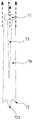
图1是一实施例提供的电子烟雾化器的示意图;1 is a schematic diagram of an electronic cigarette vaporizer provided by an embodiment;
图2是图1中管状元件的结构示意图;Fig. 2 is the structural representation of the tubular element in Fig. 1;
图3是图1中柔化器件的结构示意图;FIG. 3 is a schematic structural diagram of the softening device in FIG. 1;
图4是图1中雾化组件的剖面结构示意图;Fig. 4 is the sectional structure schematic diagram of the atomizing assembly in Fig. 1;
图5是图4的雾化组件的立体结构示意图;Fig. 5 is the three-dimensional structure schematic diagram of the atomization assembly of Fig. 4;
图6是又一实施例提供的雾化组件的剖面结构示意图;6 is a schematic cross-sectional structure diagram of an atomizing assembly provided by another embodiment;
图7是图6的雾化组件的立体结构示意图;Fig. 7 is the perspective structure schematic diagram of the atomizing assembly of Fig. 6;
图8是又一实施例提供的雾化组件的剖面结构示意图;8 is a schematic cross-sectional structure diagram of an atomizing assembly provided by another embodiment;
图9是图8的雾化组件的立体结构示意图;Fig. 9 is the three-dimensional structure schematic diagram of the atomization assembly of Fig. 8;
图10是一实施例提供的电子烟的示意图。FIG. 10 is a schematic diagram of an electronic cigarette provided by an embodiment.
具体实施方式Detailed ways
为了便于理解本实用新型,下面结合附图和具体实施方式,对本实用新型进行更详细的说明。In order to facilitate the understanding of the present utility model, the present utility model will be described in more detail below with reference to the accompanying drawings and specific embodiments.
本实用新型实施例的电子烟雾化器,其用于对液体烟油进行加热雾化,产生供吸食的气溶胶;在一个实施例中,其结构参见图1所示,包括:The electronic cigarette atomizer according to the embodiment of the present invention is used to heat and atomize the liquid e-liquid to generate an aerosol for smoking; in one embodiment, its structure is shown in FIG. 1 , including:
外壳体10,形成电子烟雾化器的外部结构;并且从图1中可以看出,该外壳体10呈内部为中空的结构,用于安装各功能零件。The
管状元件50,可以由硬质耐热聚合物或者金属材料制成,用作为气流通道输出气溶胶;The
用于存储烟油的储油腔20,在图1实施例中由管状元件50外壁与外壳体10内壁之间的空间限定出;The
为了防止储油腔20内的烟油从外壳体10渗漏出,在外壳体10的底端设置有硅胶座30、以及端盖件40。In order to prevent the e-liquid in the
管状元件50内安装有雾化组件60,用于从储油腔20内吸取烟油,并对烟油进行加热雾化生成气溶胶;在图1实施例中,雾化组件60包括用于吸取和传导烟油的柱状多孔体61,该多孔体61同轴设置于管状元件50内部;并且多孔体61具有沿轴向贯穿的通孔611,以及设置于通孔611的内壁上的发热元件62,该发热元件62呈沿通孔611的轴向方向延伸的螺旋形状。An
当然,管状元件50与多孔体61外侧壁相对的部位开设有导油孔51,以使储油腔20内的烟油通过该导油孔51传递至多孔体61外侧壁上,烟油从多孔体61的外侧壁被吸收,如图1中箭头R1所示,而后由多孔体61内部微孔孔隙的毛细浸润被传递至通孔611的内壁面上,被发热元件62加热雾化生成气溶胶,并逸出至通孔611内。Of course, an
同时,为了便于管状元件50和雾化组件60在外壳体10内的安装和固定,硅胶座30上设置有朝管状元件50延伸出的环状的插接部31;管状元件50的上端与外壳体10邻接、下端插入至插接部31内,并抵接在硅胶座30上,从而形成固定。At the same time, in order to facilitate the installation and fixation of the
在气流路径设计中,端盖40上开设有至少一个进气口11,用于在抽吸过程中供外部大气进入外壳体10内;硅胶座30上开设有使进气口11与多孔体61的通孔611气流连通的气道32;并且在外壳体10的上端开设有与管状元件50的内部中空连通的出气口12;在抽吸的过程中,气流路径如图1中箭头R2所示,外部大气由进气口11进入、经气道32流入通孔611,并携带通孔611内的气溶胶经管状元件50的内部中空输出至出气口12被用户吸食。In the airflow path design, the
在图1实施例中,管状元件50内还设有柔化器件70,在气流方向上位于雾化组件60下游,可以使通孔611内的气溶胶向出气口12输出时,在柔化器件70的阻挡下,绕开柔化器件70从柔化器件70与管状元件50的内壁之间的间隙流向出气口12,一方面气溶胶中粒径较大的颗粒被截留在柔化器件70上,而较小粒径的气溶胶可在流动路径中围绕柔化器件70转向,降低了大液滴被吸入的风险;另一方面,加大了气溶胶到达出口的路径、增加了气溶胶与空气的相互作用时间,降低了气溶胶的温度。In the embodiment of FIG. 1 , the
参见图1和图3所示,柔化器件70的设置,使得气流从通孔611围绕柔化器件70转向时,这一部位的容积减小从而增大湍流;而在沿靠近出气口12的方向,柔化器件70至少一部分呈截面积逐渐减小,在图1和图3中可以看出,柔化器件70整体呈上端小而下端大的形状,从而在靠近出口的部位增大气流通道的容积减小湍流,从而整体减小用户吸入的气溶胶的颗粒粒度。Referring to FIGS. 1 and 3 , the setting of the softening
在图3所示更加优选的实施方式中,柔化器件70包括靠近出气口12的第一端71、以及与第一端71相对的第二端72;柔化器件70表面上设有至少一个延伸至第一端71的凹槽73,当然图3中优选采用的数量为4个,在增大气流通道的容积的同时,提升气溶胶与柔化器件70的接触面积,有助于提升对气溶胶中液滴的粘滞,具有过滤效果。In a more preferred embodiment shown in FIG. 3 , the softening
并且第二端72沿多孔体61轴向方向投影的至少一部分覆盖通孔611,从而使得从通孔611输出的气流尽可能被柔化器件70阻碍,提升大粒径液滴的粘附过滤效果。同时根据图1和图3可以看出,第二端72呈从边缘向中心凹陷的形状,从而使第二端72的表面呈倾斜形状,并且第二端72的边缘设有至少一个朝多孔体61延伸出的尖头部721,用于对第二端72表面上凝聚的液滴进行引导,使其从边缘通过尖头部721滴落至多孔体61上,进而被重新吸收利用。And at least a part of the projection of the
为了防止从尖头部721滴落至多孔体61上的液滴流向通孔611内,在雾化组件60还包括挡沿63,用于阻挡液滴从多孔体61的上表面流入至通孔611内。在图4和图5所示的实施方式中,挡沿63由发热元件62的至少一部分形成,从通孔611延伸出的筒状结构部分形成以上挡沿63。具体在图4中可以详细看出,发热元件62包括圆筒形形状的电连接部分621,以及沿通孔611的轴向方向延伸的发热丝部分622,圆筒形形状的电连接部分621至少一部分凸出至通孔611上端,形成挡沿63。In order to prevent the droplets from the
在图6和图7所示的实施方式中,多孔体61包括两个部分,包括沿径向方向向外依次设置的第一多孔部610和第二多孔部620;第一多孔部610至少一部分沿轴向方向相对第二多孔部620凸出,从而形成挡沿63a。在实施中,第一多孔部610采用多孔陶瓷体制备,第二多孔部620采用耐热聚合物弹性多孔体。In the embodiment shown in FIG. 6 and FIG. 7 , the
在图8至图9所示的实施方式中,多孔体61延伸出的围绕通孔611的凸沿结构,进而形成挡沿63b。并且在图8和图9中,为了便于多孔体61的紧密安装,在多孔体61的外侧壁靠近上端或者下端的部位套设有第一弹性密封圈64和第二弹性密封圈65。防止烟油从导油孔51进入管状元件50内之后从与多孔体61之间的间隙渗漏。In the embodiments shown in FIG. 8 to FIG. 9 , the protruding edge structure extending from the
本实用新型一实施例还提出一种包含有以上电子烟雾化器的电子烟,参见图10所示,将发热元件62两端的导电引脚,分别连接至一电池/电源装置200的正/负极,即可在供电的状态下使发热元件62对多孔体61通过毛细浸润吸取或传导的烟油进行加热雾化生成供吸食的气溶胶,实现抽吸。An embodiment of the present invention also proposes an electronic cigarette including the above electronic cigarette vaporizer. Referring to FIG. 10 , the conductive pins at both ends of the
需要说明的是,本实用新型的说明书及其附图中给出了本实用新型的较佳的实施例,但并不限于本说明书所描述的实施例,进一步地,对本领域普通技术人员来说,可以根据上述说明加以改进或变换,而所有这些改进和变换都应属于本实用新型所附权利要求的保护范围。It should be noted that the preferred embodiments of the present utility model are given in the description of the present invention and the accompanying drawings, but are not limited to the embodiments described in the present specification. , can be improved or transformed according to the above description, and all these improvements and transformations should belong to the protection scope of the appended claims of the present utility model.
Claims (11)
Priority Applications (1)
| Application Number | Priority Date | Filing Date | Title |
|---|---|---|---|
| CN201921304316.4UCN211048398U (en) | 2019-08-13 | 2019-08-13 | Electronic Cigarettes and Electronic Cigarettes |
Applications Claiming Priority (1)
| Application Number | Priority Date | Filing Date | Title |
|---|---|---|---|
| CN201921304316.4UCN211048398U (en) | 2019-08-13 | 2019-08-13 | Electronic Cigarettes and Electronic Cigarettes |
Publications (1)
| Publication Number | Publication Date |
|---|---|
| CN211048398Utrue CN211048398U (en) | 2020-07-21 |
Family
ID=71581440
Family Applications (1)
| Application Number | Title | Priority Date | Filing Date |
|---|---|---|---|
| CN201921304316.4UActiveCN211048398U (en) | 2019-08-13 | 2019-08-13 | Electronic Cigarettes and Electronic Cigarettes |
Country Status (1)
| Country | Link |
|---|---|
| CN (1) | CN211048398U (en) |
Cited By (4)
| Publication number | Priority date | Publication date | Assignee | Title |
|---|---|---|---|---|
| CN114176254A (en)* | 2020-09-15 | 2022-03-15 | 深圳市合元科技有限公司 | Aerosol generating system and heater |
| CN115670013A (en)* | 2022-09-29 | 2023-02-03 | 深圳市合元科技有限公司 | An atomizer and its electronic atomization device |
| CN116801740A (en)* | 2021-12-29 | 2023-09-22 | 韩国烟草人参公社 | Filter segment, aerosol-generating article and system comprising such an aerosol-generating article |
| RU2819330C1 (en)* | 2020-08-05 | 2024-05-17 | Филип Моррис Продактс С.А. | Replaceable module for device for generation of aerosol and flavoring substance, heating system for device for generation of aerosol and flavoring substance, device for generating aerosol and flavoring substance and method for creating air flow through replaceable module for device for generating aerosol and flavoring substance |
- 2019
- 2019-08-13CNCN201921304316.4Upatent/CN211048398U/enactiveActive
Cited By (4)
| Publication number | Priority date | Publication date | Assignee | Title |
|---|---|---|---|---|
| RU2819330C1 (en)* | 2020-08-05 | 2024-05-17 | Филип Моррис Продактс С.А. | Replaceable module for device for generation of aerosol and flavoring substance, heating system for device for generation of aerosol and flavoring substance, device for generating aerosol and flavoring substance and method for creating air flow through replaceable module for device for generating aerosol and flavoring substance |
| CN114176254A (en)* | 2020-09-15 | 2022-03-15 | 深圳市合元科技有限公司 | Aerosol generating system and heater |
| CN116801740A (en)* | 2021-12-29 | 2023-09-22 | 韩国烟草人参公社 | Filter segment, aerosol-generating article and system comprising such an aerosol-generating article |
| CN115670013A (en)* | 2022-09-29 | 2023-02-03 | 深圳市合元科技有限公司 | An atomizer and its electronic atomization device |
Similar Documents
| Publication | Publication Date | Title |
|---|---|---|
| JP7321228B2 (en) | An aerosol generating system that uses the venturi effect to deliver a substrate to a heater element | |
| JP6895021B2 (en) | Aerosol generator and system | |
| CN205831079U (en) | Large-volume lung electrophilic aerosolization core and nebulizer | |
| CN111479477B (en) | Aerosol delivery device including a control body, a nebulizer body, and a cartridge, and related methods | |
| KR102851139B1 (en) | Aerosol delivery device providing flavor control | |
| JP2022504715A (en) | Heaters and liquid transport for aerosol delivery systems | |
| CN210782908U (en) | Atomizers and Electronic Cigarettes | |
| CN108135284A (en) | Tool is there are two the liquid storage device of storage space and with atomizer/liquid storage device part of liquid storage device and electrical smoking device | |
| CN108289503A (en) | Sliding attachment for electrical smoking device | |
| CN105592734A (en) | Electronic smoking devices with alternative airflow paths | |
| CN211048398U (en) | Electronic Cigarettes and Electronic Cigarettes | |
| CN105578913A (en) | electronic smoking device | |
| JP7483041B2 (en) | Ultrasonic Mist Inhaler | |
| CN207185907U (en) | A kind of capillary drain atomizer and electronic cigarette device | |
| WO2019051667A1 (en) | ATOMIZER AND ELECTRONIC CIGARETTE | |
| CN116829013A (en) | Atomizer and atomization assembly thereof | |
| CN108272139A (en) | Smoke grenade atomizer and the electronic cigarette for installing it | |
| CN111787820B (en) | Suction nozzle assembly for inhalation device comprising a replaceable base part and replaceable base part | |
| WO2018112766A1 (en) | Vaporizer | |
| CN112315029A (en) | Efficient leakage-proof oil smoke bomb | |
| CN207185906U (en) | A kind of atomizer and electronic cigarette device with lead rod structure | |
| CN218474035U (en) | Atomizer and electronic atomization device | |
| CN215347034U (en) | Atomizers and Electronic Atomizers | |
| CN117064101A (en) | Aerosol generating system, and co-operable atomizer and flavour release device | |
| CN114867374A (en) | Aerosol generating device |
Legal Events
| Date | Code | Title | Description |
|---|---|---|---|
| GR01 | Patent grant | ||
| GR01 | Patent grant |