CN211023572U - Novel emergency stretcher - Google Patents
Novel emergency stretcherDownload PDFInfo
- Publication number
- CN211023572U CN211023572UCN201922049371.XUCN201922049371UCN211023572UCN 211023572 UCN211023572 UCN 211023572UCN 201922049371 UCN201922049371 UCN 201922049371UCN 211023572 UCN211023572 UCN 211023572U
- Authority
- CN
- China
- Prior art keywords
- rod
- stretcher
- clamping block
- fixedly connected
- sleeve
- Prior art date
- Legal status (The legal status is an assumption and is not a legal conclusion. Google has not performed a legal analysis and makes no representation as to the accuracy of the status listed.)
- Active
Links
- 238000003780insertionMethods0.000claimsabstractdescription26
- 230000037431insertionEffects0.000claimsabstractdescription26
- 239000004744fabricSubstances0.000claimsabstractdescription10
- 238000000034methodMethods0.000description6
- 230000000694effectsEffects0.000description5
- 238000010586diagramMethods0.000description2
- 238000012986modificationMethods0.000description2
- 230000004048modificationEffects0.000description2
- 230000009286beneficial effectEffects0.000description1
- 201000010099diseaseDiseases0.000description1
- 208000037265diseases, disorders, signs and symptomsDiseases0.000description1
- 238000002474experimental methodMethods0.000description1
- 230000001900immune effectEffects0.000description1
- 238000009434installationMethods0.000description1
- 239000000463materialSubstances0.000description1
- 230000002503metabolic effectEffects0.000description1
- 238000012544monitoring processMethods0.000description1
- 230000000144pharmacologic effectEffects0.000description1
- 238000012546transferMethods0.000description1
- 238000003466weldingMethods0.000description1
Images

Landscapes
- Handcart (AREA)
Abstract
Translated fromChinese
Description
Translated fromChinese技术领域technical field
本实用新型涉及医疗担架技术领域,具体为一种新型急救担架。The utility model relates to the technical field of medical stretchers, in particular to a novel emergency stretcher.
背景技术Background technique
医疗器械,是指单独或者组合使用于人体的仪器、设备、器具、材料或者其他物品,包括所需要的软件,其用于人体体表及体内的作用不是用药理学、免疫学或者代谢的手段获得,但是可能有这些手段参与并起一定的辅助作用,旨在达到对疾病的预防、诊断、治疗、监护、缓解,急救过程中将伤员转移至救护车需要使用担架,但是现有的担架在使用过程中不便于收纳,在救护车中占据较大空间,给担架使用带来不便。Medical devices refer to instruments, equipment, appliances, materials or other items that are used alone or in combination on the human body, including the required software, whose effects on the human body surface and body are not obtained by pharmacological, immunological or metabolic means , but these means may be involved and play a certain auxiliary role, aiming at preventing, diagnosing, treating, monitoring, and relieving the disease. During the first aid process, the transfer of the wounded to the ambulance requires the use of stretchers, but the existing stretchers are in use. It is inconvenient to store during the process, and occupies a large space in the ambulance, which brings inconvenience to the use of the stretcher.
实用新型内容Utility model content
本实用新型的目的在于提供一种新型急救担架,具备便携的优点,解决了现有的担架在使用过程中不便于收纳,在救护车中占据较大空间,给担架使用带来不便的问题。The purpose of the utility model is to provide a novel emergency stretcher, which has the advantage of being portable, and solves the problem that the existing stretcher is inconvenient for storage during use, occupies a large space in the ambulance, and brings inconvenience to the use of the stretcher.
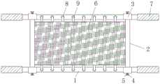
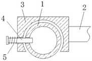
为实现上述目的,本实用新型提供如下技术方案:一种新型急救担架,包括横杆,所述横杆之间设置有固定杆,所述固定杆的两端均固定连接有卡块,所述卡块与横杆的表面卡接,所述卡块的外部活动连接有插杆,所述插杆的表面套设有第一复位弹簧,所述固定杆之间固定连接有担架布。In order to achieve the above purpose, the present utility model provides the following technical solutions: a novel emergency stretcher, comprising a cross bar, a fixing bar is arranged between the horizontal bars, and both ends of the fixing bar are fixedly connected with clamping blocks, and the The clamping block is clamped with the surface of the cross bar, an insertion rod is movably connected to the outside of the clamping block, a first return spring is sleeved on the surface of the insertion rod, and a stretcher cloth is fixedly connected between the fixing rods.
优选的,所述横杆的数量为两个,所述横杆的表面开设有固定孔,所述固定孔的内腔卡接有拉带,所述拉带远离固定孔内腔的一端与担架布固定连接。Preferably, the number of the cross bars is two, the surface of the cross bars is provided with a fixing hole, the inner cavity of the fixing hole is clamped with a pulling strap, and the end of the pulling strap away from the inner cavity of the fixing hole is connected to the stretcher. Cloth fixed connection.
优选的,所述横杆底部的两侧均固定连接有套管,所述套管的两侧均开设有限位滑孔,所述套管的内腔活动连接有支腿,所述支腿的底部通过轴承活动连接有行走轮。Preferably, both sides of the bottom of the crossbar are fixedly connected with sleeves, both sides of the sleeve are provided with limited sliding holes, and the inner cavity of the sleeve is movably connected with legs. The bottom is movably connected with a traveling wheel through a bearing.
优选的,所述支腿的两侧均固定连接有螺纹杆,所述螺纹杆的一端延伸至限位滑孔的外部,所述螺纹杆位于限位滑孔外部一端的表面螺纹连接有螺纹套。Preferably, both sides of the legs are fixedly connected with threaded rods, one end of the threaded rod extends to the outside of the limit sliding hole, and a surface of the threaded rod located outside the limit sliding hole is threadedly connected with a threaded sleeve .
优选的,所述横杆的两端均套设有防滑套,所述防滑套的表面设置有防滑纹,所述横杆表面的两侧均开设有插孔,且插杆延伸至插孔的内腔。Preferably, both ends of the crossbar are provided with anti-skid sleeves, the surface of the anti-skid sleeve is provided with anti-slip patterns, both sides of the surface of the crossbar are provided with insertion holes, and the insertion rods extend to the holes of the insertion holes. lumen.
与现有技术相比,本实用新型的有益效果如下:Compared with the prior art, the beneficial effects of the present utility model are as follows:
1、本实用新型通过拉动插杆,插杆对第一复位弹簧进行挤压,插杆会从横杆表面的插孔内脱离,从而卡块与横杆脱离卡接,旋转螺纹套,螺纹套与螺纹杆脱离固定,从而可将支腿从套管的内腔抽出,经过拆卸后,便于对担架进行携带,减小了收储面积,方便使用,解决了现有的担架在使用过程中不便于收纳,在救护车中占据较大空间,给担架使用带来不便的问题。1. The utility model pulls the insertion rod, and the insertion rod squeezes the first return spring, and the insertion rod is disengaged from the jack on the surface of the crossbar, so that the clamping block and the crossbar are disengaged from the clamping connection, and the threaded sleeve is rotated, and the threaded sleeve is removed. It is detached and fixed from the threaded rod, so that the outrigger can be pulled out from the inner cavity of the casing. After disassembly, it is convenient to carry the stretcher, which reduces the storage area and is convenient for use. It is easy to store, occupies a large space in the ambulance, and brings inconvenience to the use of the stretcher.
2、本实用新型通过设置第一复位弹簧,起到了安装时带动插杆复位的效果,通过设置固定孔和拉带,起到了对担架布固定的效果,通过设置支腿,起到了可推行的效果,通过设置限位滑孔,起到了对螺纹杆限位的效果,通过设置螺纹杆和螺纹套,起到了对支腿固定的效果。2. By setting the first reset spring, the utility model has the effect of driving the insertion rod to reset during installation; by setting the fixing hole and the pull strap, it has the effect of fixing the stretcher cloth; As a result, by setting the limit sliding hole, the effect of limiting the position of the threaded rod is achieved, and by setting the threaded rod and the threaded sleeve, the effect of fixing the outrigger is achieved.
附图说明Description of drawings
图1为本实用新型结构示意图;Fig. 1 is the structural representation of the utility model;
图2为本实用新型左视结构示意图;Fig. 2 is the left side view structure schematic diagram of the present utility model;
图3为本实用新型支腿结构示意图。Figure 3 is a schematic diagram of the structure of the outrigger of the present invention.
图中:1、横杆;2、固定杆;3、卡块;4、插杆;5、第一复位弹簧;6、担架布;7、防滑套;8、固定孔;9、拉带;10、套管;11、限位滑孔;12、支腿;13、螺纹杆;14、螺纹套。In the figure: 1. Cross bar; 2. Fixed bar; 3. Block; 4. Insertion bar; 5. First return spring; 6. Stretcher cloth; 7. Anti-skid cover; 8. Fixing hole; 10. Sleeve; 11. Limiting sliding hole; 12. Outrigger; 13. Threaded rod; 14. Threaded sleeve.
具体实施方式Detailed ways
下面将结合本实用新型实施例中的附图,对本实用新型实施例中的技术方案进行清楚、完整地描述,显然,所描述的实施例仅仅是本实用新型一部分实施例,而不是全部的实施例。基于本实用新型中的实施例,本领域普通技术人员在没有做出创造性劳动前提下所获得的所有其他实施例,都属于本实用新型保护的范围。The technical solutions in the embodiments of the present utility model will be clearly and completely described below with reference to the accompanying drawings in the embodiments of the present utility model. Obviously, the described embodiments are only a part of the embodiments of the present utility model, rather than all the implementations. example. Based on the embodiments of the present invention, all other embodiments obtained by those of ordinary skill in the art without creative work fall within the protection scope of the present invention.
本实用新型的横杆1、固定杆2、卡块3、插杆4、第一复位弹簧5、担架布6、防滑套7、固定孔8、拉带9、套管10、限位滑孔11、支腿12、螺纹杆13和螺纹套14部件均为通用标准件或本领域技术人员知晓的部件,其结构和原理都为本技术人员均可通过技术手册得知或通过常规实验方法获知。The utility model has the
请参阅图1-3,一种新型急救担架,包括横杆1,横杆1底部的两侧均固定连接有套管10,套管10的两侧均开设有限位滑孔11,套管10的内腔活动连接有支腿12,支腿12的底部通过轴承活动连接有行走轮,支腿12的两侧均固定连接有螺纹杆13,螺纹杆13的一端延伸至限位滑孔11的外部,螺纹杆13位于限位滑孔11外部一端的表面螺纹连接有螺纹套14,横杆1之间设置有固定杆2,固定杆2的两端均固定连接有卡块3,卡块3与横杆1的表面卡接,卡块3的外部活动连接有插杆4,插杆4的表面套设有第一复位弹簧5,固定杆2之间固定连接有担架布6,横杆1的数量为两个,横杆1的表面开设有固定孔8,固定孔8的内腔卡接有拉带9,拉带9远离固定孔8内腔的一端与担架布6固定连接,横杆1的两端均套设有防滑套7,防滑套7的表面设置有防滑纹,横杆1表面的两侧均开设有插孔,且插杆4延伸至插孔的内腔,通过拉动插杆4,插杆4对第一复位弹簧5进行挤压,插杆4会从横杆1表面的插孔内脱离,从而卡块3与横杆1脱离卡接,旋转螺纹套14,螺纹套14与螺纹杆13脱离固定,从而可将支腿12从套管10的内腔抽出,经过拆卸后,便于对担架进行携带,减小了收储面积,方便使用,解决了现有的担架在使用过程中不便于收纳,在救护车中占据较大空间,给担架使用带来不便的问题。Please refer to Figure 1-3, a new type of emergency stretcher, including a
使用时,通过拉动插杆4,插杆4对第一复位弹簧5进行挤压,插杆4会从横杆1表面的插孔内脱离,从而卡块3与横杆1脱离卡接,旋转螺纹套14,螺纹套14与螺纹杆13脱离固定,从而可将支腿12从套管10的内腔抽出,经过拆卸后,便于对担架进行携带,减小了收储面积,方便使用。During use, by pulling the
本申请文件中使用到的标准零件均可以从市场上购买,而且根据说明书和附图的记载均可以进行订制,各个零件的具体连接方式均采用现有技术中成熟的螺栓、铆钉、焊接等常规手段,机械、零件和设备均采用现有技术中常规的型号,控制方式是通过控制器来自动控制,控制器的控制电路通过本领域的技术人员简单编程即可实现,属于本领域的公知常识,并且本申请文主要用来保护机械装置,所以本申请文不再详细解释控制方式和电路连接。The standard parts used in this application document can be purchased from the market, and can be customized according to the description in the description and the attached drawings. The specific connection method of each part adopts the mature bolts, rivets, welding, etc. in the prior art. Conventional means, machinery, parts and equipment all use conventional models in the prior art, the control method is automatically controlled by the controller, and the control circuit of the controller can be realized by simple programming by those skilled in the art, which belongs to the well-known in the art. Common sense, and this application is mainly used to protect mechanical devices, so this application will not explain the control method and circuit connection in detail.
尽管已经示出和描述了本实用新型的实施例,对于本领域的普通技术人员而言,可以理解在不脱离本实用新型的原理和精神的情况下可以对这些实施例进行多种变化、修改、替换和变型,本实用新型的范围由所附权利要求及其等同物限定。Although the embodiments of the present invention have been shown and described, it will be understood by those skilled in the art that various changes and modifications can be made to these embodiments without departing from the principles and spirit of the present invention , alternatives and modifications, the scope of the present invention is defined by the appended claims and their equivalents.
Claims (5)
Translated fromChinesePriority Applications (1)
| Application Number | Priority Date | Filing Date | Title |
|---|---|---|---|
| CN201922049371.XUCN211023572U (en) | 2019-11-25 | 2019-11-25 | Novel emergency stretcher |
Applications Claiming Priority (1)
| Application Number | Priority Date | Filing Date | Title |
|---|---|---|---|
| CN201922049371.XUCN211023572U (en) | 2019-11-25 | 2019-11-25 | Novel emergency stretcher |
Publications (1)
| Publication Number | Publication Date |
|---|---|
| CN211023572Utrue CN211023572U (en) | 2020-07-17 |
Family
ID=71563066
Family Applications (1)
| Application Number | Title | Priority Date | Filing Date |
|---|---|---|---|
| CN201922049371.XUActiveCN211023572U (en) | 2019-11-25 | 2019-11-25 | Novel emergency stretcher |
Country Status (1)
| Country | Link |
|---|---|
| CN (1) | CN211023572U (en) |
Cited By (1)
| Publication number | Priority date | Publication date | Assignee | Title |
|---|---|---|---|---|
| CN112569049A (en)* | 2020-11-02 | 2021-03-30 | 李广有 | Stretcher is used in emergency call patient's transportation |
- 2019
- 2019-11-25CNCN201922049371.XUpatent/CN211023572U/enactiveActive
Cited By (1)
| Publication number | Priority date | Publication date | Assignee | Title |
|---|---|---|---|---|
| CN112569049A (en)* | 2020-11-02 | 2021-03-30 | 李广有 | Stretcher is used in emergency call patient's transportation |
Similar Documents
| Publication | Publication Date | Title |
|---|---|---|
| CN205127298U (en) | But tensile auxiliary device of shank of angle regulation and height | |
| CN211023572U (en) | Novel emergency stretcher | |
| CN206964700U (en) | A kind of animal and veterinary check device | |
| CN207306802U (en) | A kind of field emergency folding-type portable stretcher | |
| CN212090164U (en) | Rehabilitation department is with supplementary running gear | |
| CN206424246U (en) | A kind of flatcar and sick bed instrument rack | |
| CN206183293U (en) | Oral cavity photography draws excavator to construct | |
| CN205031440U (en) | Novel multi -functional operation transfer car | |
| CN204618633U (en) | Nursing bed for tumor gynecology | |
| CN205144927U (en) | Multifunctional care bed | |
| CN205054614U (en) | Laborsaving stretcher | |
| CN201572187U (en) | Tank-type folding medical examination bed | |
| CN215779238U (en) | Emergency transfer first-aid kit | |
| CN203280693U (en) | Walk assisting leg | |
| CN217660633U (en) | Auxiliary walking device for postoperative patient | |
| CN105055089B (en) | A kind of application process of reassembling type stretcher | |
| CN212816807U (en) | Emergency nursing stretcher | |
| CN204671412U (en) | One can rolling stretcher | |
| CN106264999A (en) | A kind of nursing auxiliary walking device | |
| CN206792585U (en) | A kind of Simple stretcher | |
| CN201022797Y (en) | Stretcher carrier | |
| CN213250779U (en) | Emergency department is with diagnosing bed | |
| CN204446170U (en) | A kind of experimental rabbit acupuncture fixture | |
| CN204684107U (en) | A kind of nursing auxiliary walking device | |
| CN204446335U (en) | Split strecher car |
Legal Events
| Date | Code | Title | Description |
|---|---|---|---|
| GR01 | Patent grant | ||
| GR01 | Patent grant | ||
| TR01 | Transfer of patent right | ||
| TR01 | Transfer of patent right | Effective date of registration:20201021 Address after:110000, No. 44, Xiaohe Road, Dadong District, Liaoning, Shenyang Patentee after:LIAONING CANCER HOSPITAL & INSTITUTE Address before:2-6-3, No.4, nanqingzhen Road, Shenhe District, Shenyang City, Liaoning Province Patentee before:He Xiaodan |