CN210977265U - A turnable unitized lattice tower crane foundation lifting device - Google Patents
A turnable unitized lattice tower crane foundation lifting deviceDownload PDFInfo
- Publication number
- CN210977265U CN210977265UCN201920983275.XUCN201920983275UCN210977265UCN 210977265 UCN210977265 UCN 210977265UCN 201920983275 UCN201920983275 UCN 201920983275UCN 210977265 UCN210977265 UCN 210977265U
- Authority
- CN
- China
- Prior art keywords
- handrail
- tower crane
- crane foundation
- unit
- side beams
- Prior art date
- Legal status (The legal status is an assumption and is not a legal conclusion. Google has not performed a legal analysis and makes no representation as to the accuracy of the status listed.)
- Active
Links
Images


Landscapes
- Jib Cranes (AREA)
Abstract
Description
Translated fromChinese技术领域technical field
本实用新型涉及格构式塔吊基础辅助设备技术领域,具体涉及一种可周转单元化的格构式塔吊基础上人装置。The utility model relates to the technical field of lattice type tower crane foundation auxiliary equipment, in particular to a turnover unitized lattice type tower crane foundation climbing device.
背景技术Background technique
格构式塔吊基础主要由预埋于灌注桩内的钢格构柱及在其上浇筑的钢筋混凝土承台或焊接钢板组成,以此作为承受塔吊荷载的基础。这种结构形式在深基坑工程运用中相对于传统方式(例如:①开挖塔吊基础土方,将塔吊基础作用在地下室底板处;②利用混凝土桩作为塔吊基础)具有以下优点:施工方法简便,相对工期较短,质量安全有保证;格构柱材料可回收,成本相对较低的特点。因此,目前在较大深基坑地下室施工过程中,更多地采用格构式塔吊基础作为现场塔吊的基础形式。The lattice tower crane foundation is mainly composed of steel lattice columns pre-buried in cast-in-place piles and reinforced concrete caps or welded steel plates poured on them, as the basis for bearing the tower crane load. Compared with traditional methods in the application of deep foundation pit engineering (for example: ① excavating the earthwork of the tower crane foundation, and applying the tower crane foundation to the basement floor; ② using concrete piles as the tower crane foundation), it has the following advantages: the construction method is simple, Relatively short construction period, quality and safety are guaranteed; lattice column material can be recycled, and the cost is relatively low. Therefore, at present, in the construction process of large deep foundation pit basement, the lattice tower crane foundation is more used as the foundation form of the on-site tower crane.
在深基坑地下室结构施工过程中,若采用格构式塔吊基础,塔吊操作人员需从地下室开挖面采用上人装置,上至塔基混凝土承台,进而到达塔吊操作室。现有的上人装置通常采用钢管搭设上人马镫或爬梯,由于其为临时搭设装置,安全性与灵活性较差;且在进行下一标高楼层作业时,还需要将整个架体拆除,吊装完成需再次安装上人装置,施工工艺较为繁琐,反复拆搭耗时耗力,成本投入较大。因此,一种可周转、施工简便、更加安全与经济的格构式塔吊基础专用上人装置亟待开发。In the construction process of the basement structure of the deep foundation pit, if the lattice tower crane foundation is used, the tower crane operator needs to use the upper device from the basement excavation surface, up to the tower foundation concrete bearing platform, and then to the tower crane operation room. The existing climbing devices usually use steel pipes to set up stirrups or climbing ladders. Because they are temporary devices, the safety and flexibility are poor; and when the operation on the next elevation floor is carried out, the entire frame body needs to be dismantled and hoisted. After the completion, it is necessary to re-install the upper-hand device, the construction process is relatively cumbersome, the repeated dismantling and erection are time-consuming and labor-intensive, and the cost investment is relatively large. Therefore, there is an urgent need to develop a special access device for lattice tower crane foundations, which can be turned around, is easy to construct, and is safer and more economical.
发明内容SUMMARY OF THE INVENTION
本实用新型的目的在于,针对现有技术的不足,提供一种拆装方便且可多次利用的可周转单元化的格构式塔吊基础上人装置。The purpose of the present utility model is to provide a revolving unitized lattice tower crane foundation lifting device that is convenient for disassembly and assembly and can be used multiple times, aiming at the deficiencies of the prior art.
本实用新型采用的技术方案为:一种可周转单元化的格构式塔吊基础上人装置,包括扶手单元,以及若干依次首尾相连的标准单元,所述扶手单元固定于塔吊基础的顶部,扶手单元的的下端与第一个标准单元相连;所述扶手单元固定于格构式塔吊基础的外壁。The technical scheme adopted by the utility model is as follows: a revolvable unitized lattice tower crane foundation lift device, comprising a handrail unit, and a number of standard units connected end to end in sequence, the handrail unit is fixed on the top of the tower crane foundation, and the handrail unit is The lower end of the unit is connected with the first standard unit; the handrail unit is fixed on the outer wall of the lattice tower crane foundation.
按上述方案,所述标准单元包括两根侧梁、若干踏步,以及附着结构,所述两根侧梁平行设置,且两者分别通过附着结构与格构式塔吊基础的外壁连接固定;所述踏步沿侧梁的长度方向间隔安装于两根侧梁之间。According to the above scheme, the standard unit includes two side beams, a number of steps, and an attachment structure, the two side beams are arranged in parallel, and the two are respectively connected and fixed with the outer wall of the lattice tower crane foundation through the attachment structure; the The steps are installed between the two side beams at intervals along the length direction of the side beams.
按上述方案,所述侧梁的上端固连连接板,上一个标准单元的侧梁下端通过螺栓与下一个标准单元侧梁上端的连接板相连。According to the above solution, the upper end of the side beam is fixedly connected to the connecting plate, and the lower end of the side beam of the previous standard unit is connected to the connecting plate at the upper end of the side beam of the next standard unit through bolts.
按上述方案,在两根侧梁的外侧沿侧梁的长度方向间隔安装若干拦腰杆。According to the above scheme, a number of lumbar bars are installed at intervals along the length direction of the side beams on the outside of the two side beams.
按上述方案,所述附着结构包括附着挑梁和附着斜拉梁,所述附着挑梁的一端与踏步及侧梁连接固定,附着挑梁的另一端与格构式塔吊基础的外壁相连;所述附着斜拉梁的上端与格构式塔吊基础的外壁相连,附着斜拉梁的下端与附着挑梁相连。According to the above scheme, the attachment structure includes an attached cantilever beam and an attached cable-stayed beam, one end of the attached cantilever beam is connected and fixed with the step and the side beam, and the other end of the attached cantilever beam is connected with the outer wall of the lattice tower crane foundation; The upper end of the attached cable-stayed beam is connected with the outer wall of the lattice tower crane foundation, and the lower end of the attached cable-stayed beam is connected with the attached cantilever beam.
按上述方案,所述扶手单元包括两根与第一个标准单元的两根侧梁上端对应相连的扶手立杆;每根扶手立杆分别配设一根扶手横杆和扶手斜杆,所述扶手立杆的下端与扶手横杆的一端相连,扶手横杆通过膨胀螺栓固定于格构式塔吊基础的混凝土承台上,扶手横杆的另一端与扶手斜杆的下端固连,扶手斜杆的上端与扶手立杆的上端固连。According to the above solution, the handrail unit includes two handrail vertical bars correspondingly connected to the upper ends of the two side beams of the first standard unit; The lower end of the handrail vertical bar is connected with one end of the handrail cross bar. The handrail cross bar is fixed on the concrete bearing platform of the lattice tower crane foundation through expansion bolts. The other end of the handrail cross bar is fixed with the lower end of the handrail inclined bar. The upper end of the armrest is fixedly connected with the upper end of the armrest pole.
按上述方案,在两根扶手立杆的外侧沿扶手立杆的长度方向分别间隔设有若干拦腰杆。According to the above solution, a number of waist bars are respectively arranged on the outside of the two handrail vertical bars along the length direction of the handrail vertical bars.
按上述方案,附着斜拉梁和附着挑梁均分别采用角钢制作。According to the above scheme, the attached cable-stayed beam and the attached cantilever beam are made of angle steel respectively.
按上述方案,连接板采用钢板制作。According to the above scheme, the connecting plate is made of steel plate.
本实用新型的有益效果为:本实用新型所述上人装置由扶手单元和若干标准单元连接而成,便于局部安装和拆除;拆除后的各单元可再次利用,减少了材料的浪费,节约了施工成本;扶手单元和标准单元可分别预制加工,加快了施工进度。本实用新型中上下标准单元之间的侧梁均通过螺栓连接、扶手横杆与塔吊基础的混凝土承台通过螺栓连接,这种可拆式连接可完整地保护各单元。本实用新型中涉及的构件采用角钢、槽钢、圆钢或钢板制成,取材方便。本实用新型结构设计合理,实用性强。The beneficial effects of the utility model are as follows: the boarding device of the utility model is formed by connecting the handrail unit and several standard units, which is convenient for partial installation and dismantling; the dismantled units can be reused, which reduces the waste of materials and saves money. Construction cost; handrail units and standard units can be prefabricated separately, which speeds up the construction progress. In the utility model, the side beams between the upper and lower standard units are connected by bolts, and the handrail crossbar and the concrete bearing platform of the tower crane foundation are connected by bolts, and the detachable connection can completely protect each unit. The components involved in the utility model are made of angle steel, channel steel, round steel or steel plate, which is convenient to obtain. The utility model has reasonable structural design and strong practicability.
附图说明Description of drawings
图1为本实用新型一个具体实施例的结构示意图。FIG. 1 is a schematic structural diagram of a specific embodiment of the present invention.
图2为本实施例中扶手单元的结构示意图。FIG. 2 is a schematic structural diagram of the armrest unit in this embodiment.
图3为本实施例中标准单元的结构示意图。FIG. 3 is a schematic structural diagram of a standard cell in this embodiment.
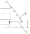
其中:1、拦腰杆;2、附着挑梁;3、附着斜拉梁;4、踏步;5、侧梁;6、连接板;7、扶手横杆;8、扶手斜杆;9、扶手立杆;10、混凝土承台;11、塔吊基础。Among them: 1, the middle bar; 2, attached to the beam; 3, attached to the inclined-stayed beam; 4, the step; 5, the side beam; 6, the connecting plate; 7, the handrail crossbar; Rod; 10. Concrete cap; 11. Tower crane foundation.
具体实施方式Detailed ways
为了更好地理解本实用新型,下面结合附图和具体实施例对本实用新型作进一步地描述。In order to better understand the present utility model, the present utility model will be further described below with reference to the accompanying drawings and specific embodiments.
如图1所示的一种可周转单元化的格构式塔吊基础上人装置,包括扶手单元,以及若干依次首尾相连的标准单元,所述扶手单元固定于塔吊基础11顶部的混凝土承台10上,扶手单元的的下端与第一个标准单元相连;所述扶手单元固定于格构式塔吊基础11的外壁。As shown in FIG. 1 , a revolvable unitized lattice tower crane foundation lifting device includes a handrail unit and a number of standard units connected end to end in sequence, and the handrail unit is fixed on the
如图3所示,所述标准单元包括两根侧梁5、若干踏步4,以及附着结构,所述两根侧梁5平行设置,且两者分别通过附着结构与格构式塔吊基础11的外壁连接固定;所述踏步4沿侧梁5的长度方向间隔安装于两根侧梁5之间(可为焊接)。优选地,所述侧梁5的上端通过螺栓固连连接板6,上一个标准单元的侧梁5下端通过螺栓与下一个标准单元侧梁5上端的连接板6相连。优选地,在两根侧梁5的外侧沿侧梁5的长度方向间隔安装若干拦腰杆1(可为焊接)。优选地,所述附着结构包括附着挑梁2和附着斜拉梁3,所述附着挑梁2的一端与踏步4及侧梁5连接固定(可为焊接),附着挑梁2的另一端与格构式塔吊基础11的外壁相连(可为焊接);所述附着斜拉梁3的上端与格构式塔吊基础11的外壁相连(可为焊接),附着斜拉梁3的下端与附着挑梁2相连(可为焊接)。As shown in FIG. 3 , the standard unit includes two
如图2所示,所述扶手单元包括两根与第一个标准单元的两根侧梁5上端对应相连的扶手立杆9,两根扶手立杆9之间的距离至少可容纳一人通过;每根扶手立杆9分别配设一根扶手横杆7和扶手斜杆8,所述扶手立杆9的下端与扶手横杆7的一端相连,扶手横杆7通过膨胀螺栓固定于格构式塔吊基础11的混凝土承台10上,扶手横杆7的另一端与扶手斜杆8的下端固连,扶手斜杆8的上端与扶手立杆9的上端固连。优选地,在两根扶手立杆9的外侧沿扶手立杆9的长度方向分别间隔设有若干拦腰杆1(可为焊接)。As shown in Figure 2, the handrail unit includes two handrail
本实用新型中,附着斜拉梁3和附着挑梁2均分别采用角钢制作;连接板6采用钢板制作,其上设两组螺栓孔,一组四个与下一个标准单元的侧梁5连接,另一组四个与上一个标准单元的侧梁5连接;拦腰杆1采用圆钢制作,其通过焊接方式与其他结构比如侧梁5或扶手立杆9相连;踏步4采用槽钢制作,其通过焊接方式与两个侧梁5及附着挑梁2连接;侧梁5采用槽钢制作;扶手立杆9、扶手横杆7和扶手斜杆8均分别采用角钢制作,扶手横杆7与塔吊基础11的混凝土承台10通过膨胀螺栓连接,扶手横杆7上开设两组分设于两端的膨胀螺栓孔。In the utility model, the attached inclined-stayed
本实用新型的具体安装流程为:The specific installation process of the utility model is as follows:
步骤一、根据塔吊基础11的高度,制作扶手单元和标准单元;
步骤二、通过螺栓将扶手单元安装在塔吊基础11的混凝土承台10上;
步骤三、安装第一个标准单元,第一个标准单元的上端与扶手单元相连;第一个标准单元的两根侧梁5间通过螺栓进行调节和固定,附着结构采用焊接与格构式塔吊基础11的外壁连接固定;
步骤四,自上而下依次各标准单元,在安装过程中,为保证塔吊操作人员能够顺利上行,因此至少确保使用过程中最底部一榀挂架无拦腰杆1,待底部需安挂架后再可安装拦腰杆1。
本实用新型涉及的部件均采用钢板或型钢制作而成,只是为了说明采用此种材料制作与安装工艺均比较简单,容易理解掌握,并不代表仅能采用此类材料。本图例提及的各部件造型均为最佳结构造型,若采用其它相似造型,即有类似结构,但只是安装方位或数量、尺寸、连接方式、材质的改变均属本实用新型保护范围。The components involved in the present invention are all made of steel plates or profiled steels, just to illustrate that the fabrication and installation processes using such materials are relatively simple and easy to understand and grasp, but it does not mean that only such materials can be used. The shapes of the components mentioned in this illustration are the best structural shapes. If other similar shapes are used, there will be similar structures, but only changes in the installation orientation or quantity, size, connection method, and material belong to the protection scope of the present invention.
最后应说明的是,以上仅为本实用新型的优选实施例而已,并不用于限制本实用新型,尽管参照实施例对本实用新型进行了详细的说明,对于本领域的技术人员来说,其依然可以对前述各实施例所记载的技术方案进行修改,或者对其中部分技术特征进行等同替换,但是凡在本实用新型的精神和原则之内,所作的任何修改、等同替换、改进等,均应包含在本实用新型的保护范围之内。Finally, it should be noted that the above are only the preferred embodiments of the present utility model, and are not intended to limit the present utility model. Although the present utility model has been described in detail with reference to the embodiments, for those skilled in the art, the The technical solutions described in the foregoing embodiments can be modified, or some technical features thereof can be equivalently replaced, but any modification, equivalent replacement, improvement, etc. made within the spirit and principle of the present utility model shall be Included within the scope of protection of the present invention.
Claims (9)
Translated fromChinesePriority Applications (1)
| Application Number | Priority Date | Filing Date | Title |
|---|---|---|---|
| CN201920983275.XUCN210977265U (en) | 2019-06-27 | 2019-06-27 | A turnable unitized lattice tower crane foundation lifting device |
Applications Claiming Priority (1)
| Application Number | Priority Date | Filing Date | Title |
|---|---|---|---|
| CN201920983275.XUCN210977265U (en) | 2019-06-27 | 2019-06-27 | A turnable unitized lattice tower crane foundation lifting device |
Publications (1)
| Publication Number | Publication Date |
|---|---|
| CN210977265Utrue CN210977265U (en) | 2020-07-10 |
Family
ID=71458618
Family Applications (1)
| Application Number | Title | Priority Date | Filing Date |
|---|---|---|---|
| CN201920983275.XUActiveCN210977265U (en) | 2019-06-27 | 2019-06-27 | A turnable unitized lattice tower crane foundation lifting device |
Country Status (1)
| Country | Link |
|---|---|
| CN (1) | CN210977265U (en) |
Cited By (1)
| Publication number | Priority date | Publication date | Assignee | Title |
|---|---|---|---|---|
| CN114105008A (en)* | 2021-12-20 | 2022-03-01 | 中国建筑第二工程局有限公司 | Can have enough to meet need formula tower crane passageway of going up people that climbs along with climbing frame |
- 2019
- 2019-06-27CNCN201920983275.XUpatent/CN210977265U/enactiveActive
Cited By (2)
| Publication number | Priority date | Publication date | Assignee | Title |
|---|---|---|---|---|
| CN114105008A (en)* | 2021-12-20 | 2022-03-01 | 中国建筑第二工程局有限公司 | Can have enough to meet need formula tower crane passageway of going up people that climbs along with climbing frame |
| CN114105008B (en)* | 2021-12-20 | 2023-07-28 | 中国建筑第二工程局有限公司 | Turnover type tower crane manned channel climbing along with climbing frame |
Similar Documents
| Publication | Publication Date | Title |
|---|---|---|
| WO2022142999A1 (en) | Hoisting device for bridge water surface pile tie beam and construction method therefor | |
| CN113136853B (en) | A prefabricated drilling platform and process for bare rock pile foundation in reservoir area | |
| CN108360380B (en) | Bridge pier column construction operation platform and construction method thereof | |
| WO2022252829A1 (en) | Liftable scaffold, lifting and installation methods thereof, and construction method for prefabricated building | |
| CN214993171U (en) | Bridge bent cap construction is with assembled sectional shelf-unit platform | |
| CN114606870A (en) | Integral dismantling method for hoop-method bent cap supporting system | |
| CN210977265U (en) | A turnable unitized lattice tower crane foundation lifting device | |
| CN214883028U (en) | A door font template gallows for steel-concrete composite beam | |
| CN116044137B (en) | Cantilever formwork construction method suitable for large-section vertical shaft concrete structure wall | |
| CN216947902U (en) | A hydraulic lifting truss platform system for high pier overturning construction | |
| CN216947881U (en) | Formwork support of I-shaped composite beam cast-in-situ bridge deck | |
| CN216305335U (en) | Assembled elevator shaft operating platform for high-rise building | |
| CN214270021U (en) | Operation radius lengthening device for tower crane | |
| CN214274677U (en) | A beret support and protection structure for shallow buried underground pipelines | |
| CN212295581U (en) | Instrument formula elevartor shaft operation platform | |
| CN210563531U (en) | Steel structure support for building protection | |
| CN111088904B (en) | An integral hoisting device and process for a 100-meter-high cylindrical iron chimney steel frame | |
| CN210659227U (en) | Exterior wall formwork system free of external scaffold | |
| CN210685313U (en) | Safe convenient house steel connection structure | |
| CN209742334U (en) | Steel structure corridor bottom curtain wall construction platform | |
| CN222043943U (en) | An inverted trapezoidal structural support for a large-span upper beam of a super-high bridge tower | |
| CN223034004U (en) | Top operation platform of steel pipe pile construction tool section | |
| CN217079853U (en) | Channel structure capable of being turned over | |
| CN215210559U (en) | Anti-scouring large-span continuous beam stress support | |
| CN222878490U (en) | An integral movable pedestrian bridge used in the construction of the superstructure of a high-pile wharf |
Legal Events
| Date | Code | Title | Description |
|---|---|---|---|
| GR01 | Patent grant | ||
| GR01 | Patent grant |