CN210961475U - An electric pressure cooker with an air fryer head - Google Patents
An electric pressure cooker with an air fryer headDownload PDFInfo
- Publication number
- CN210961475U CN210961475UCN201920573750.6UCN201920573750UCN210961475UCN 210961475 UCN210961475 UCN 210961475UCN 201920573750 UCN201920573750 UCN 201920573750UCN 210961475 UCN210961475 UCN 210961475U
- Authority
- CN
- China
- Prior art keywords
- cavity
- hole
- plate
- shell
- cover
- Prior art date
- Legal status (The legal status is an assumption and is not a legal conclusion. Google has not performed a legal analysis and makes no representation as to the accuracy of the status listed.)
- Active
Links
- 238000010438heat treatmentMethods0.000claimsabstractdescription56
- 238000005485electric heatingMethods0.000claimsabstractdescription24
- 230000003068static effectEffects0.000claimsdescription3
- 238000000034methodMethods0.000claimsdescription2
- XLYOFNOQVPJJNP-UHFFFAOYSA-NwaterSubstancesOXLYOFNOQVPJJNP-UHFFFAOYSA-N0.000abstract2
- 238000009434installationMethods0.000description4
- 230000002093peripheral effectEffects0.000description2
- 230000006835compressionEffects0.000description1
- 238000007906compressionMethods0.000description1
- 238000001816coolingMethods0.000description1
- 238000005516engineering processMethods0.000description1
- 238000012986modificationMethods0.000description1
- 230000004048modificationEffects0.000description1
- 238000005580one pot reactionMethods0.000description1
- 239000007787solidSubstances0.000description1
Images


Landscapes
- Cookers (AREA)
- Frying-Pans Or Fryers (AREA)
Abstract
Description
Translated fromChinese技术领域technical field
本实用新型涉及一种电压力锅,尤其是一种带空气热源装置的电压力锅。The utility model relates to an electric pressure cooker, in particular to an electric pressure cooker with an air heat source device.
背景技术Background technique
目前现有技术,如图1所示,一种电压力锅上,包括锅盖组件1和锅体组件2,锅体组件2包括内胆、外锅、电发热盘、中环、外壳和底座,外锅与中环连接,电发热盘设在外锅内,内胆与电发热盘配合,外锅的锅牙伸入中环的环形凹槽内;锅盖组件1包括锅盖、环绕锅盖的装盖圈和与装饰圈一体成型的座体,座体包括沿锅盖的径向部和轴向部,锅盖的内扣板与外锅的外扣板旋合。存在问题是:功能单一,只能作为普通的电压力锅使用,In the current prior art, as shown in FIG. 1 , an electric pressure cooker includes a lid assembly 1 and a pot body assembly 2. The pot body assembly 2 includes an inner pot, an outer pot, an electric heating plate, a middle ring, an outer shell and a base. The pot is connected with the middle ring, the electric heating plate is arranged in the outer pot, the inner pot is matched with the electric heating plate, and the pot teeth of the outer pot extend into the annular groove of the middle ring; the pot cover assembly 1 includes a pot cover and a cover ring surrounding the pot cover. and a seat body integrally formed with the decorative ring, the seat body includes a radial portion and an axial portion along the pot cover, and the inner gusset plate of the pot cover is screwed with the outer gusset plate of the outer pot. The problem is that it has a single function and can only be used as an ordinary electric pressure cooker.
实用新型内容Utility model content
本实用新型的目的是:提供一种带空气炸锅头的电压力锅,它与电压力锅的锅体组件配合,实现热空气煎炸、或炒功能。The purpose of the utility model is to provide an electric pressure cooker with an air fryer head, which cooperates with the pot body components of the electric pressure cooker to realize the function of hot air frying or frying.
本实用新型是这样实现的:一种带空气炸锅头的电压力锅,包括锅盖组件和锅体组件,锅盖组件包括锅盖和环绕锅盖的装盖圈,锅盖上设有内扣板;锅体组件包括内胆、外锅、电发热盘、中环、外壳和底座,外锅与中环连接,电发热盘设在外锅内,内胆与电发热盘配合,外锅的外扣板伸入中环的环形凹槽内;锅盖组件的锅体组件可拆卸配合;其特征在于:所述中环上设有在一条直径线两端设有上开口的左腔体和上开口的右腔体,左腔体和右腔体与中环的环形凹槽相通,左腔体的底板上设有左定位凸起,右腔体的底板上设有右凸起,右凸起中空下开口,顶板上设有伸出孔;The utility model is realized as follows: an electric pressure cooker with an air fryer head, comprising a pot cover assembly and a pot body assembly, the pot cover assembly includes a pot cover and a cover ring surrounding the pot cover, and the pot cover is provided with an inner buckle The pot body assembly includes an inner pot, an outer pot, an electric heating plate, a middle ring, a shell and a base, the outer pot is connected with the middle ring, the electric heating plate is arranged in the outer pot, the inner pot is matched with the electric heating plate, and the outer plate of the outer pot is connected. It extends into the annular groove of the middle ring; the pot body assembly of the pot cover assembly can be detachably matched; it is characterized in that: the middle ring is provided with a left cavity with an upper opening and a right cavity with an upper opening on both ends of a diameter line The left cavity and the right cavity communicate with the annular groove of the middle ring. The bottom plate of the left cavity is provided with a left positioning protrusion, and the bottom plate of the right cavity is provided with a right protrusion. There are protruding holes on it;
还包括一空气加热装置、子耦合器和母耦合器;Also includes an air heating device, sub-coupler and female coupler;
所述空气加热装置包括下开口的外壳、内壳、下开口的发热腔、热风出风罩、电发热体、电机、上轴流叶轮、下轴流叶轮和操控面板,The air heating device includes an outer shell with a lower opening, an inner shell, a heating cavity with a lower opening, a hot air outlet hood, an electric heating element, a motor, an upper axial flow impeller, a lower axial flow impeller and a control panel,
外壳的顶板上设有顶出风孔,外壳的周向壁板上设有进风孔,外壳的下端内设有卡舌;外壳的下端设有在一条直径线两侧的下开口的左容置腔和下开口的右容置腔;The top plate of the outer casing is provided with an ejection air hole, the peripheral wall plate of the outer casing is provided with an air inlet hole, and the lower end of the outer casing is provided with a tab; and the right receiving cavity with the lower opening;
内壳的顶板上设有贯通孔和环绕贯通孔的电机安装位;周向壁板上设有进风孔,周向壁板的下部设有卡位;内壳的下开口的设有下开口的下沉孔;内壳的下端设有一条直径线两侧的左盖板和右盖板,左盖板设有左定位腔,右盖板上设有贯通孔;The top plate of the inner shell is provided with a through hole and a motor installation position surrounding the through hole; the circumferential wall plate is provided with an air inlet hole, and the lower part of the circumferential wall plate is provided with a clamping position; the lower opening of the inner shell is provided with a sinking hole with a lower opening ; The lower end of the inner shell is provided with a left cover plate and a right cover plate on both sides of a diameter line, the left cover plate is provided with a left positioning cavity, and the right cover plate is provided with a through hole;
母耦合器设在右凸起内并从伸出孔中伸出;电机固定在内壳的电机安装位上,内壳嵌入外壳内,左盖板和右盖板分别嵌入左容置腔和右容置腔内,子耦合器的固定在右盖板上,子耦合器与贯通孔相对;卡舌与卡位嵌合,内壳顶板的连接柱伸入外壳顶板上的固定座的沉孔内,螺钉穿过连接柱与固定座螺合;发热腔设在内壳内,发热腔的环形沿板与下沉孔的顶板固定连接,发热腔的顶板与内壳的顶板之间有间隙;电机的轴伸入发热腔内,上轴流叶轮设在发热腔和内壳的顶部之间的间隙内,下轴流叶轮设在发热腔内,电发热体设在发热腔内,热风出风罩覆盖发热腔的下开口;外壳的进风孔、内胆的进风孔和发热腔的进风孔相配合;The female coupler is arranged in the right protrusion and protrudes from the protruding hole; the motor is fixed on the motor installation position of the inner shell, the inner shell is embedded in the outer shell, and the left cover plate and the right cover plate are respectively embedded in the left accommodating cavity and the right In the accommodating cavity, the sub-coupler is fixed on the right cover plate, and the sub-coupler is opposite to the through hole; the tab is fitted with the clamping position, and the connecting column of the top plate of the inner shell extends into the countersunk hole of the fixing seat on the top plate of the outer shell , the screws pass through the connecting column and screw with the fixed seat; the heating chamber is set in the inner shell, the annular edge plate of the heating chamber is fixedly connected with the top plate of the sinking hole, and there is a gap between the top plate of the heating chamber and the top plate of the inner shell; the motor The shaft extends into the heating cavity, the upper axial flow impeller is arranged in the gap between the heating cavity and the top of the inner shell, the lower axial flow impeller is arranged in the heating cavity, the electric heating element is arranged in the heating cavity, and the hot air is discharged from the hood. Cover the lower opening of the heating chamber; the air inlet holes of the shell, the air inlet holes of the inner tank and the air inlet holes of the heating chamber are matched;
外壳的下端与所述中环的环形凹槽的底板支撑配合,热风出风罩伸入所述内胆内,内胆的上端与发热腔的环形沿板支撑配合;左定位凸起插入左定位腔内,母耦合器插入子耦合器内电连接;操控面板设在外壳上。The lower end of the outer shell is supported and matched with the bottom plate of the annular groove of the middle ring, the hot air outlet cover extends into the inner pot, and the upper end of the inner pot is supported and matched with the annular edge plate of the heating cavity; the left positioning protrusion is inserted into the left positioning cavity Inside, the female coupler is inserted into the sub-coupler for electrical connection; the control panel is arranged on the casing.
所述的一种带空气炸锅头的电压力锅,其特殊之处在于:所述外壳的顶板上设有沉孔,沉孔的底板的中心设置所述顶出风孔、环绕顶出风孔的套筒和设在套筒上端的若干个凸起;The electric pressure cooker with an air fryer head is special in that the top plate of the casing is provided with a countersunk hole, and the center of the bottom plate of the countersunk hole is provided with the top-out air hole, which surrounds the top-out air hole. the sleeve and several protrusions arranged on the upper end of the sleeve;
还包括顶盖,顶盖与外壳的沉孔嵌合,顶盖的外周向上与沉孔的内壁之间有间隙,顶盖与凸起支撑配合,相邻二个凸起之间的顶盖和套筒构成导向出风孔。It also includes a top cover, the top cover is fitted with the countersunk hole of the shell, there is a gap between the outer circumference of the top cover and the inner wall of the counterbore, the top cover is supported and matched with the protrusion, the top cover between the adjacent two protrusions and the The sleeve constitutes a guide air outlet.
所述的一种带空气炸锅头的电压力锅,其特殊之处在于:所述顶盖上设有若干个扣钩;The special feature of the electric pressure cooker with an air fryer head is that a plurality of hooks are arranged on the top cover;
所述沉孔的底板上设有扣钩孔,扣钩穿过扣钩孔与沉孔的底板扣合。The bottom plate of the counterbore is provided with a clasp hole, and the clasp passes through the clasp hole and is fastened to the bottom plate of the counterbore.
所述的一种带空气炸锅头的电压力锅,其特殊之处在于:所述外壳的顶部边缘设有半圆形梯级,The special feature of the electric pressure cooker with an air fryer head is that the top edge of the outer shell is provided with a semicircular step,
还包括半圆形提手,提手两端设有半轴,It also includes a semi-circular handle with half shafts at both ends of the handle.
半轴与半圆形梯级上部的外壳上的半轴孔转动配合,静止状态,提手与半圆形梯级嵌合;使用时,提手直立。The half shaft is rotatably matched with the half shaft hole on the casing on the upper part of the semicircular step. In a static state, the handle is fitted with the semicircular step; when in use, the handle is upright.
所述的一种带空气炸锅头的电压力锅,其特殊之处在于:还包括微动开关、顶杆和压力弹簧,The described electric pressure cooker with an air fryer head is special in that it also includes a micro switch, a top rod and a pressure spring,
所述内壳的下沉孔的顶板上设有下开口的容置腔,容置腔的顶板上设有导向孔;A accommodating cavity with a lower opening is provided on the top plate of the sinking hole of the inner shell, and a guide hole is provided on the top plate of the accommodating cavity;
所述发热腔的环形沿板上设有伸出孔;The annular edge plate of the heating chamber is provided with a protruding hole;
顶杆上设有挡盘,There is a baffle plate on the top rod,
顶杆的上端穿过压力弹簧和导向孔伸出容置腔,压力弹簧与挡盘和容置腔的顶板配合;顶杆的下端穿过伸出孔伸出容置腔;The upper end of the ejector rod protrudes out of the accommodating cavity through the pressure spring and the guide hole, and the pressure spring cooperates with the baffle plate and the top plate of the accommodating cavity; the lower end of the ejector rod protrudes out of the accommodating cavity through the protruding hole;
微动开关设在内壳上,顶杆的上端与微动开关配合、下端与所述内胆的上端配合。The micro switch is arranged on the inner shell, the upper end of the ejector rod is matched with the micro switch, and the lower end is matched with the upper end of the inner pot.
本实用新型一种带空气炸锅头的电压力锅,空气炸锅头向内胆内吹热风,加热内胆的食物。与现有技术中相比,增加了功能,一锅多用。The utility model relates to an electric pressure cooker with an air fryer head. The air fryer head blows hot air into the inner pot to heat the food in the inner pot. Compared with the prior art, functions are increased, and one pot can be used for multiple purposes.
附图说明Description of drawings
图1是本实用新型现在技术的立体图。FIG. 1 is a perspective view of the present technology of the present invention.
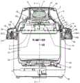
图2是本实用新型的剖视图。Figure 2 is a cross-sectional view of the present invention.
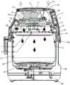
图3是图2的A—A视图。FIG. 3 is an A-A view of FIG. 2 .
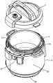
图4是本实用新型的立体图之一。Figure 4 is one of the perspective views of the present invention.
图5是本实用新型的立体图之二。Fig. 5 is the second perspective view of the present invention.
图6是本实用新型的立体分解图之一。Figure 6 is one of the three-dimensional exploded views of the present invention.
图7是本实用新型的立体分解图之二。FIG. 7 is the second exploded perspective view of the present invention.
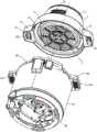
图8是本实用新型空气加热装置的立体分解图之一。FIG. 8 is one of the perspective exploded views of the air heating device of the present invention.
图9是本实用新型空气加热装置的立体分解图之二。Fig. 9 is the second exploded perspective view of the air heating device of the present invention.
具体实施方式Detailed ways
下面结合附图对本实用新型作进一步描述。The present utility model will be further described below in conjunction with the accompanying drawings.
如图1、图2、图3所示,一种带空气炸锅头的电压力锅,包括锅盖组件1和锅体组件2,锅体组件2包括内胆21、外锅22、电发热盘23、中环24、外壳25和底座26,外锅22与中环24连接,电发热盘23设在外锅22内,内胆21与电发热盘23配合,外锅22的外扣板221伸入中环24的环形凹槽内;外锅22也称中锅;锅盖组件1包括锅盖和环绕锅盖的装盖圈,锅盖上设有内扣板;锅盖组件1和锅体组件2可拆卸配合。As shown in Figures 1, 2, and 3, an electric pressure cooker with an air fryer head includes a lid assembly 1 and a pot body assembly 2. The pot body assembly 2 includes an
所述中环24上设有在一条直径线两端设有上开口的左腔体241和上开口的右腔体242,左腔体241和右腔体242与中环24的环形凹槽相通,左腔体241的底板上设有左定位凸起2411,右腔体242的底板上设有右凸起 2421,右凸起2421中空下开口,顶板上设有伸出孔;The
还包括一空气加热装置3、子耦合器3A和母耦合器3B;Also includes an air heating device 3, a
如图3、图4、图8、图9所示,所述空气加热装置3包括下开口的外壳4、内壳5、下开口的发热腔6、热风出风罩7、电发热体8、电机9、上轴流叶轮101、下轴流叶轮102和操控面板31,As shown in Figure 3, Figure 4, Figure 8, Figure 9, the air heating device 3 includes an
电发热体8由电发热管螺旋绕在一个平面上制成;The
外壳4的顶板上设有顶出风孔,外壳的周向壁板上设有进风孔41,外壳的下端内设有卡舌42;外壳4的下端设有在一条直径线两侧的下开口的左容置腔43和下开口的右容置腔44;The top plate of the
内壳5的顶板上设有贯通孔51和环绕贯通孔的电机安装位;周向壁板上设有进风孔52,周向壁板的下部设有卡位53;内壳5的下开口的设有下开口的下沉孔54;内壳5的下端设有一条直径线两侧的左盖板55和右盖板 56,左盖板55设有左定位腔551,右盖板56上设有贯通孔;The top plate of the
发热腔6的下开口上设有环形沿板61和进风孔62;The lower opening of the
热风出风罩7的上开口上设有环形座板71;An
母耦合器3B设在右凸起2421内,并从右凸起2421上的伸出孔中伸出;电机9固定在内壳5的电机安装位上,内壳5嵌入外壳4内,左盖板55和右盖板56分别嵌入左容置腔43和右容置腔44内,子耦合器3A的固定在右盖板56上,子耦合器3A与贯通孔相对;卡舌42与卡位53嵌合,内壳5 顶板的连接柱5A伸入外壳4顶板上的固定座4A的沉孔内,螺钉穿过连接柱5A与固定座4A螺合;发热腔6设在内壳5内,发热腔6的环形沿板61 与下沉孔54的顶板固定连接,发热腔6的顶板与内壳5的顶板之间有间隙;电机9的轴伸入发热腔6内,上轴流叶轮101设在发热腔6和内壳5的顶部之间的间隙内,下轴流叶轮102设在发热腔6内,电发热体8设在发热腔6内并位于下轴流叶轮102的下方,热风出风罩7覆盖发热腔6的下开口,环形座板71与环形沿板61固定连接;外壳的进风孔41、内胆的进风孔52和发热腔6的进风孔62相配合;The female coupler 3B is arranged in the right protrusion 2421 and protrudes from the protruding hole on the right protrusion 2421; the motor 9 is fixed on the motor installation position of the inner shell 5, the inner shell 5 is embedded in the outer shell 4, and the left cover The plate 55 and the right cover plate 56 are embedded in the left accommodating cavity 43 and the right accommodating cavity 44 respectively, the sub-coupler 3A is fixed on the right cover plate 56, and the sub-coupler 3A is opposite to the through hole; 53 is fitted, the connecting column 5A of the top plate of the inner shell 5 extends into the countersunk hole of the fixing seat 4A on the top plate of the outer shell 4, the screw passes through the connecting column 5A and is screwed with the fixing seat 4A; the heating chamber 6 is arranged in the inner shell 5, The annular edge plate 61 of the heating chamber 6 is fixedly connected with the top plate of the sinking hole 54, and there is a gap between the top plate of the heating chamber 6 and the top plate of the inner shell 5; the shaft of the motor 9 extends into the heating chamber 6, and the upper axial flow impeller 101 It is arranged in the gap between the heating chamber 6 and the top of the inner shell 5, the lower axial flow impeller 102 is arranged in the heating chamber 6, and the electric heating element 8 is arranged in the heating chamber 6 and is located below the lower axial flow impeller 102, and the hot air is heated. The
外壳4的下端与所述中环24的环形凹槽的底板支撑配合,热风出风罩 7伸入所述内胆21内,内胆21的上端与发热腔6的环形沿板61支撑配合;左定位凸起2422插入左定位腔551内,母耦合器3B穿过右盖板56上的贯通孔插入子耦合器3A内电连接;母耦合器3B与锅体组件2内的电源电连接。左容置腔43和下开口的右容置腔44分别嵌入左腔体241和右腔体242 内;操控面板31设在外壳4上。The lower end of the
如图2、图6、图8、图9所示,还包括微动开关13、顶杆14和压力弹簧,As shown in Figure 2, Figure 6, Figure 8, Figure 9, it also includes a
所述内壳5的下沉孔54的顶板上设有下开口的容置腔57,容置腔57 的顶板上设有导向孔;The top plate of the
所述发热腔6的环形沿板61上设有伸出孔611;The
顶杆14上设有挡盘,The
顶杆14的上端穿过压力弹簧和容置腔57的顶板上的导向孔伸出容置腔57,压力弹簧与挡盘和容置腔57的顶板配合;顶杆14的下端穿过伸出孔611伸出容置腔;The upper end of the
微动开关13设在内壳5上,顶杆14的上端与微动开关13配合、下端与所述内胆21的上端配合;The
微动开关13作为电源开关或信号源,采用这样结构,只有在空气加热装置3与中环24正确接合,且环形沿板61与内胆21的对接,才能操作控制,空气加热装置3才能工作,消除了安全隐患。The
如图3所示,空气加热装置3工作时,电发热体8工作,电机通电转动,外界空气经外壳4的进风孔41、内壳5的进风孔52、发热腔6的进风孔62进入加热腔6内,下轴流叶轮102将电发热体8加热的空气,吹入内胆21内,加热内胆的食物;如实心箭头方向;As shown in FIG. 3 , when the air heating device 3 works, the
外界空气经外壳4的进风孔41、内壳5的进风孔52进入加热腔6和内壳5之间的间隙内,风经贯通孔51、电机9,从外壳4的顶出风孔流出,将电机散热;如空芯箭头方向。The outside air enters the gap between the
使用时,可以是电发热体8和电发热盘23交替工作,也可以是电发热体8单独工作。使用方便。In use, the
作为本实用新型的进一步改进:所述外壳4的顶板上设有沉孔45,沉孔45的底板的中心设置所述顶出风孔、环绕顶出风孔的套筒46和设在套筒上端的若干个凸起47;As a further improvement of the present invention, the top plate of the
还包括顶盖11,顶盖11与外壳4的沉孔45嵌合,顶盖11的外周向上与沉孔45的内壁之间有间隙,顶盖11与凸起47支撑配合,相邻二个凸起 47之间的顶盖11和套筒构成导风出风孔。电机转动9转动,上轴流叶轮 101转动,进入内壳5内空气,经内壳5的贯通孔51、冷却电机9、外壳的顶出风孔、导风出风孔及顶盖11的外周向上与沉孔45的内壁之间的间隙排出。It also includes a
所述顶盖11上设有若干个扣钩111;The
所述沉孔45的底板上设有扣钩孔46,扣钩111穿过沉孔45底板上的扣钩孔48与沉孔45的底板扣合。The bottom plate of the
作为本实用新型更进一步改进:所述外壳4的顶部边缘设有半圆形梯级49,As a further improvement of the present invention: the top edge of the
还包括半圆形提手12,提手12两端设有半轴,It also includes a
半轴与半圆形梯级49上部的外壳4上的半轴孔转动配合,如图4所示,静止状态,提手12与半圆形梯级49嵌合;如图5所示,使用时,提手12 直立。手提提手12,实现空气加热装置3和锅体组件2分离。The half shaft is rotatably matched with the half shaft hole on the
消费者使用时,可以作为普通电压力锅使用,也可以单独作为空气炸锅使用。When used by consumers, it can be used as an ordinary electric pressure cooker, or it can be used alone as an air fryer.
以上所述的仅是本实用新型的优先实施方式。应当指出的是,对于本领域的普通技术人员来说,在不脱离本实用新型原理的情况下,还可以作出若干改进和变型,这也视为本实用新型的保护范围。The above are only preferred embodiments of the present invention. It should be pointed out that for those of ordinary skill in the art, without departing from the principle of the present invention, several improvements and modifications can be made, which are also regarded as the protection scope of the present invention.
Claims (5)
Applications Claiming Priority (2)
| Application Number | Priority Date | Filing Date | Title |
|---|---|---|---|
| CN2019205258075 | 2019-04-17 | ||
| CN201920525807 | 2019-04-17 |
Publications (1)
| Publication Number | Publication Date |
|---|---|
| CN210961475Utrue CN210961475U (en) | 2020-07-10 |
Family
ID=71443538
Family Applications (2)
| Application Number | Title | Priority Date | Filing Date |
|---|---|---|---|
| CN201920573750.6UActiveCN210961475U (en) | 2019-04-17 | 2019-04-24 | An electric pressure cooker with an air fryer head |
| CN201920573761.4UActiveCN210961465U (en) | 2019-04-17 | 2019-04-24 | An air fryer head mounted on an electric pressure cooker |
Family Applications After (1)
| Application Number | Title | Priority Date | Filing Date |
|---|---|---|---|
| CN201920573761.4UActiveCN210961465U (en) | 2019-04-17 | 2019-04-24 | An air fryer head mounted on an electric pressure cooker |
Country Status (1)
| Country | Link |
|---|---|
| CN (2) | CN210961475U (en) |
Cited By (1)
| Publication number | Priority date | Publication date | Assignee | Title |
|---|---|---|---|---|
| CN114129047A (en)* | 2021-12-15 | 2022-03-04 | 广东韩派电器有限公司 | Electric pressure cooker with drying and sterilizing device |
Families Citing this family (5)
| Publication number | Priority date | Publication date | Assignee | Title |
|---|---|---|---|---|
| WO2019032876A1 (en) | 2017-08-09 | 2019-02-14 | Sharkninja Operating Llc | Cooking device and components thereof |
| WO2020176477A1 (en) | 2019-02-25 | 2020-09-03 | Sharkninja Operating Llc | Cooking system with guard |
| US11678765B2 (en) | 2020-03-30 | 2023-06-20 | Sharkninja Operating Llc | Cooking device and components thereof |
| CN114680604B (en)* | 2020-12-30 | 2024-03-12 | 杭州九阳小家电有限公司 | Cooking utensil |
| CN115517557A (en)* | 2022-10-11 | 2022-12-27 | 慈溪市悦达电子科技有限公司 | Deep-fry integrative multi-functional food processor |
- 2019
- 2019-04-24CNCN201920573750.6Upatent/CN210961475U/enactiveActive
- 2019-04-24CNCN201920573761.4Upatent/CN210961465U/enactiveActive
Cited By (1)
| Publication number | Priority date | Publication date | Assignee | Title |
|---|---|---|---|---|
| CN114129047A (en)* | 2021-12-15 | 2022-03-04 | 广东韩派电器有限公司 | Electric pressure cooker with drying and sterilizing device |
Also Published As
| Publication number | Publication date |
|---|---|
| CN210961465U (en) | 2020-07-10 |
Similar Documents
| Publication | Publication Date | Title |
|---|---|---|
| CN210961475U (en) | An electric pressure cooker with an air fryer head | |
| US9803653B2 (en) | Heater pump | |
| US20160040686A1 (en) | Heating Pump | |
| US5701388A (en) | Combined heater and pump | |
| EP2221485A2 (en) | Fluid circulation pump adapted to a household appliance | |
| US11060531B2 (en) | Heating pump | |
| CN105795962B (en) | Safe water-adding type broken food machine | |
| CN210727514U (en) | An electric pressure cooker that can place an air fryer head | |
| CN204218743U (en) | Food processor | |
| CN107160730B (en) | Oil press | |
| CN107440551B (en) | Top-blowing hot air and bottom-heating three-dimensional frying pan | |
| CN220275382U (en) | Constant temperature kettle | |
| CN214678684U (en) | An air frying pan for frying and cooking | |
| CN213578064U (en) | A thick/film heating tube type electric water heater | |
| CN214128186U (en) | Pot cover assembly and cooking utensil | |
| CN213984009U (en) | Water heating device with spiral heating water channel | |
| JPH10103297A (en) | Pump with built-in heater | |
| CN218942953U (en) | Steam valve assembly and cooking utensil | |
| CN107126089A (en) | Cooker | |
| CN208677020U (en) | A kind of electric cooker that food is separated with soup | |
| CN112021931A (en) | Water pumping device for appliance coupler | |
| KR20160134128A (en) | electric cooker | |
| CN222704132U (en) | Water flow sensor with controllable silicon cooling function | |
| CN213882908U (en) | Upper cover subassembly and have its cooking utensil | |
| CN104359224A (en) | An electrical partition wall connection assembly with flow sensing |
Legal Events
| Date | Code | Title | Description |
|---|---|---|---|
| GR01 | Patent grant | ||
| GR01 | Patent grant |