CN210931221U - Sealing structure and intelligent cleaning equipment - Google Patents
Sealing structure and intelligent cleaning equipmentDownload PDFInfo
- Publication number
- CN210931221U CN210931221UCN201921473122.7UCN201921473122UCN210931221UCN 210931221 UCN210931221 UCN 210931221UCN 201921473122 UCN201921473122 UCN 201921473122UCN 210931221 UCN210931221 UCN 210931221U
- Authority
- CN
- China
- Prior art keywords
- lens
- casing
- intelligent cleaning
- sealing structure
- infrared
- Prior art date
- Legal status (The legal status is an assumption and is not a legal conclusion. Google has not performed a legal analysis and makes no representation as to the accuracy of the status listed.)
- Active
Links
- 238000004140cleaningMethods0.000titleclaimsabstractdescription186
- 238000007789sealingMethods0.000titleclaimsabstractdescription49
- 230000001681protective effectEffects0.000claimsabstractdescription32
- 239000000428dustSubstances0.000abstractdescription31
- 230000000694effectsEffects0.000abstractdescription13
- XLYOFNOQVPJJNP-UHFFFAOYSA-NwaterSubstancesOXLYOFNOQVPJJNP-UHFFFAOYSA-N0.000description73
- 239000004744fabricSubstances0.000description33
- 238000009434installationMethods0.000description19
- 239000007788liquidSubstances0.000description8
- 230000006870functionEffects0.000description6
- 238000000034methodMethods0.000description6
- 238000005108dry cleaningMethods0.000description5
- 239000000463materialSubstances0.000description5
- 230000033001locomotionEffects0.000description4
- 238000010586diagramMethods0.000description3
- 230000006872improvementEffects0.000description3
- 230000003993interactionEffects0.000description3
- 230000008569processEffects0.000description3
- 238000010408sweepingMethods0.000description3
- 239000002131composite materialSubstances0.000description2
- 238000013461designMethods0.000description2
- 238000001514detection methodMethods0.000description2
- 238000005516engineering processMethods0.000description2
- 238000012423maintenanceMethods0.000description2
- 238000012544monitoring processMethods0.000description2
- 238000003825pressingMethods0.000description2
- 238000000926separation methodMethods0.000description2
- WHXSMMKQMYFTQS-UHFFFAOYSA-NLithiumChemical compound[Li]WHXSMMKQMYFTQS-UHFFFAOYSA-N0.000description1
- 229910005813NiMHInorganic materials0.000description1
- 241001417527PempheridaeSpecies0.000description1
- 229910000831SteelInorganic materials0.000description1
- 238000009825accumulationMethods0.000description1
- 230000009471actionEffects0.000description1
- 230000006399behaviorEffects0.000description1
- 238000005452bendingMethods0.000description1
- 238000004891communicationMethods0.000description1
- 239000000356contaminantSubstances0.000description1
- 238000011161developmentMethods0.000description1
- 230000003670easy-to-cleanEffects0.000description1
- 238000001125extrusionMethods0.000description1
- 239000011521glassSubstances0.000description1
- 229910052744lithiumInorganic materials0.000description1
- 230000004807localizationEffects0.000description1
- 238000012986modificationMethods0.000description1
- 230000004048modificationEffects0.000description1
- 238000003032molecular dockingMethods0.000description1
- 239000002245particleSubstances0.000description1
- 230000000149penetrating effectEffects0.000description1
- 230000002572peristaltic effectEffects0.000description1
- 238000012545processingMethods0.000description1
- 238000005096rolling processMethods0.000description1
- 238000007790scrapingMethods0.000description1
- 239000010959steelSubstances0.000description1
- 239000000126substanceSubstances0.000description1
- 239000000725suspensionSubstances0.000description1
- 230000007704transitionEffects0.000description1
Images


Classifications
- A—HUMAN NECESSITIES
- A47—FURNITURE; DOMESTIC ARTICLES OR APPLIANCES; COFFEE MILLS; SPICE MILLS; SUCTION CLEANERS IN GENERAL
- A47L—DOMESTIC WASHING OR CLEANING; SUCTION CLEANERS IN GENERAL
- A47L11/00—Machines for cleaning floors, carpets, furniture, walls, or wall coverings
- A47L11/24—Floor-sweeping machines, motor-driven
- A—HUMAN NECESSITIES
- A47—FURNITURE; DOMESTIC ARTICLES OR APPLIANCES; COFFEE MILLS; SPICE MILLS; SUCTION CLEANERS IN GENERAL
- A47L—DOMESTIC WASHING OR CLEANING; SUCTION CLEANERS IN GENERAL
- A47L11/00—Machines for cleaning floors, carpets, furniture, walls, or wall coverings
- A47L11/28—Floor-scrubbing machines, motor-driven
- A—HUMAN NECESSITIES
- A47—FURNITURE; DOMESTIC ARTICLES OR APPLIANCES; COFFEE MILLS; SPICE MILLS; SUCTION CLEANERS IN GENERAL
- A47L—DOMESTIC WASHING OR CLEANING; SUCTION CLEANERS IN GENERAL
- A47L11/00—Machines for cleaning floors, carpets, furniture, walls, or wall coverings
- A47L11/40—Parts or details of machines not provided for in groups A47L11/02 - A47L11/38, or not restricted to one of these groups, e.g. handles, arrangements of switches, skirts, buffers, levers
- A47L11/4002—Installations of electric equipment
- A—HUMAN NECESSITIES
- A47—FURNITURE; DOMESTIC ARTICLES OR APPLIANCES; COFFEE MILLS; SPICE MILLS; SUCTION CLEANERS IN GENERAL
- A47L—DOMESTIC WASHING OR CLEANING; SUCTION CLEANERS IN GENERAL
- A47L11/00—Machines for cleaning floors, carpets, furniture, walls, or wall coverings
- A47L11/40—Parts or details of machines not provided for in groups A47L11/02 - A47L11/38, or not restricted to one of these groups, e.g. handles, arrangements of switches, skirts, buffers, levers
- A47L11/4036—Parts or details of the surface treating tools
- A—HUMAN NECESSITIES
- A47—FURNITURE; DOMESTIC ARTICLES OR APPLIANCES; COFFEE MILLS; SPICE MILLS; SUCTION CLEANERS IN GENERAL
- A47L—DOMESTIC WASHING OR CLEANING; SUCTION CLEANERS IN GENERAL
- A47L11/00—Machines for cleaning floors, carpets, furniture, walls, or wall coverings
- A47L11/40—Parts or details of machines not provided for in groups A47L11/02 - A47L11/38, or not restricted to one of these groups, e.g. handles, arrangements of switches, skirts, buffers, levers
- A47L11/4061—Steering means; Means for avoiding obstacles; Details related to the place where the driver is accommodated
- A—HUMAN NECESSITIES
- A47—FURNITURE; DOMESTIC ARTICLES OR APPLIANCES; COFFEE MILLS; SPICE MILLS; SUCTION CLEANERS IN GENERAL
- A47L—DOMESTIC WASHING OR CLEANING; SUCTION CLEANERS IN GENERAL
- A47L11/00—Machines for cleaning floors, carpets, furniture, walls, or wall coverings
- A47L11/40—Parts or details of machines not provided for in groups A47L11/02 - A47L11/38, or not restricted to one of these groups, e.g. handles, arrangements of switches, skirts, buffers, levers
- A47L11/408—Means for supplying cleaning or surface treating agents
- A47L11/4083—Liquid supply reservoirs; Preparation of the agents, e.g. mixing devices
- G—PHYSICS
- G02—OPTICS
- G02B—OPTICAL ELEMENTS, SYSTEMS OR APPARATUS
- G02B7/00—Mountings, adjusting means, or light-tight connections, for optical elements
- G02B7/02—Mountings, adjusting means, or light-tight connections, for optical elements for lenses
- A—HUMAN NECESSITIES
- A47—FURNITURE; DOMESTIC ARTICLES OR APPLIANCES; COFFEE MILLS; SPICE MILLS; SUCTION CLEANERS IN GENERAL
- A47L—DOMESTIC WASHING OR CLEANING; SUCTION CLEANERS IN GENERAL
- A47L2201/00—Robotic cleaning machines, i.e. with automatic control of the travelling movement or the cleaning operation
Landscapes
- Physics & Mathematics (AREA)
- General Physics & Mathematics (AREA)
- Optics & Photonics (AREA)
- Cleaning In General (AREA)
- Electric Vacuum Cleaner (AREA)
- Control Of Position, Course, Altitude, Or Attitude Of Moving Bodies (AREA)
Abstract
Translated fromChinese
Description
Translated fromChinese技术领域technical field
本实用新型涉及智能清洁设备技术领域,特别是涉及一种密封结构及智能清洁设备。The utility model relates to the technical field of intelligent cleaning equipment, in particular to a sealing structure and an intelligent cleaning equipment.
背景技术Background technique
随着技术的发展,出现了多种多样的自动清洁设备。比如,自动扫地机器人、自动拖地机器人等。自动清洁设备可以自动执行清洁操作,方便用户。以自动扫地机器人为例,是通过直接刮扫、真空吸尘等技术来实现对待清扫区域的自动清理,刮扫操作可以通过自动清洁设备底部的刮条和滚刷结构来实现。对于带有拖地功能的自动清扫机器人,其在进行拖地时通常需要在机器人上设置水箱,提供拖地需要的水源。With the development of technology, a variety of automatic cleaning equipment has appeared. For example, automatic sweeping robots, automatic mopping robots, etc. Automatic cleaning equipment can automatically perform cleaning operations for the convenience of users. Taking the automatic sweeping robot as an example, the automatic cleaning of the area to be cleaned is realized through technologies such as direct scraping and vacuuming. For an automatic cleaning robot with a mopping function, it is usually necessary to set a water tank on the robot when mopping the floor to provide the water source required for mopping the floor.
现有的自动清洁设备的红外沿墙模组在自动清洁设备被使用一段时间后容易积累灰尘,防尘效果较差,使得灰尘容易进入红外沿墙模组,不能对红外沿墙模组产生较好的保护效果。The infrared along the wall module of the existing automatic cleaning equipment is easy to accumulate dust after the automatic cleaning equipment is used for a period of time, and the dustproof effect is poor, so that the dust easily enters the infrared along the wall module, and cannot cause serious damage to the infrared along the wall module. good protection.
实用新型内容Utility model content
本实用新型实施例提供一种密封结构及智能清洁设备,密封结构能够对红外沿墙模组实现较好的密封效果,且具有较好的防尘效果,使得灰尘不容易进入红外沿墙模组,对红外沿墙模组具有较好的保护作用。The embodiments of the present utility model provide a sealing structure and an intelligent cleaning device. The sealing structure can achieve a better sealing effect on the infrared wall along the module, and has a better dustproof effect, so that the dust is not easy to enter the infrared wall along the module. , has a better protection effect on the infrared along the wall module.
一方面,根据本实用新型实施例提出了一种密封结构,用于密封智能清洁设备的红外沿墙模组,包括:壳体,连接于红外沿墙模组面向智能清洁设备的防护壳的一侧;镜片,与壳体相连接,镜片包覆于壳体面向防护壳的一侧,镜片包括弧形面板及设置于弧形面板的边缘部位且朝向红外沿墙模组方向延伸的连接板,弧形面板与连接板相交设置。On the one hand, according to an embodiment of the present invention, a sealing structure is proposed, which is used for sealing an infrared wall-mounted module of an intelligent cleaning device, comprising: a casing, a part connected to a protective shell of the infrared wall-mounted module facing the intelligent cleaning device. side; lens, connected with the shell, the lens is covered on the side of the shell facing the protective shell, the lens includes an arc panel and a connecting plate arranged at the edge of the arc panel and extending toward the infrared along the direction of the wall module, The arc panel and the connecting plate are set to intersect.
根据本实用新型实施例的一个方面,壳体与镜片通过卡合结构相连接,卡合结构包括相互配合的卡合扣和卡合孔,卡合扣设置于壳体和镜片中的其中一者上,卡合孔设置于壳体和镜片中的另一者上。According to an aspect of the embodiment of the present invention, the housing and the lens are connected by a snap structure, the snap structure includes a snap buckle and a snap hole that cooperate with each other, and the snap snap is disposed on one of the housing and the lens On the top, the engaging hole is arranged on the other of the shell and the lens.
根据本实用新型实施例的一个方面,至少部分连接板上设置有连接臂,卡合孔设置于连接臂的远离弧形面板的一端;其中,卡合扣设置于壳体上与卡合孔相对应的位置,以实现壳体与镜片的连接。According to an aspect of the embodiment of the present invention, at least part of the connecting plate is provided with a connecting arm, and the engaging hole is disposed at one end of the connecting arm away from the arc-shaped panel; wherein, the engaging buckle is disposed on the housing in correspondence with the engaging hole Corresponding position to realize the connection between the shell and the lens.
根据本实用新型实施例的一个方面,卡合孔为在连接板厚度方向上贯通连接板的条形通孔结构。According to an aspect of the embodiment of the present invention, the engaging hole is a strip-shaped through-hole structure penetrating the connecting plate in the thickness direction of the connecting plate.
根据本实用新型实施例的一个方面,进一步包括至少一个由弧形面板延伸出的第一延伸板,第一延伸板与弧形面板平滑过渡连接。According to an aspect of the embodiment of the present invention, it further comprises at least one first extension plate extending from the arc-shaped panel, and the first extension plate is smoothly connected with the arc-shaped panel.
根据本实用新型实施例的一个方面,进一步包括至少一个由连接板朝向远离弧形面板的方向延伸出的第二延伸板,第二延伸板与连接板相交设置。According to an aspect of the embodiment of the present invention, it further includes at least one second extension plate extending from the connecting plate in a direction away from the arc-shaped panel, and the second extending plate and the connecting plate are arranged to intersect.
根据本实用新型实施例的一个方面,壳体包括相互配合的上壳和下壳,上壳与下壳可拆卸连接。According to an aspect of the embodiment of the present invention, the casing includes an upper casing and a lower casing that cooperate with each other, and the upper casing and the lower casing are detachably connected.
另一方面,根据本实用新型实施例提出了一种智能清洁设备,包括:机器主体,内部设置有红外沿墙模组;上述的密封结构,设置于红外沿墙模组外侧,用于密封红外沿墙模组;防护壳,设置于密封结构外侧,且与机器主体配合连接,用于防护机器主体。On the other hand, according to the embodiment of the present invention, an intelligent cleaning device is proposed, which includes: a machine body, an infrared wall along the module is arranged inside; the above-mentioned sealing structure is arranged on the outside of the infrared wall along the module for sealing the infrared Along the wall module; the protective shell is arranged on the outside of the sealing structure, and is connected with the main body of the machine to protect the main body of the machine.
根据本实用新型实施例的另一个方面,防护壳上与弧形面板相对应的位置设置通孔。According to another aspect of the embodiment of the present invention, a through hole is provided on the protective shell at a position corresponding to the arc-shaped panel.
根据本实用新型实施例的另一个方面,镜片面向防护壳的一侧表面与防护壳的内壁紧密贴合。According to another aspect of the embodiment of the present invention, the surface of the side of the lens facing the protective case is closely fitted with the inner wall of the protective case.
本实用新型实施例提供的密封结构及智能清洁设备,密封结构用于密封智能清洁设备的红外沿墙模组,密封结构包括壳体和镜片,壳体连接于红外沿墙模组面向智能清洁设备的防护壳的一侧;镜片与壳体相连接,镜片包覆于壳体面向防护壳的一侧表面,镜片包括弧形面板及设置于弧形面板的边缘部位且朝向红外沿墙模组方向延伸的连接板。壳体与镜片的配合共同实现对红外沿墙模组的密封,密封效果较好,使得灰尘不容易进入红外沿墙模组,对红外沿墙模组具有较好的保护作用。In the sealing structure and the intelligent cleaning device provided by the embodiment of the present invention, the sealing structure is used to seal the infrared along the wall module of the intelligent cleaning device. One side of the protective shell; the lens is connected with the shell, the lens is covered on the side surface of the shell facing the protective shell, and the lens includes an arc-shaped panel and is arranged on the edge of the arc-shaped panel and faces the infrared along the wall module direction Extended connection plate. The cooperation of the housing and the lens realizes the sealing of the infrared along the wall module, and the sealing effect is good, so that the dust is not easy to enter the infrared along the wall module, and has a good protective effect on the infrared along the wall module.
附图说明Description of drawings
下面将参考附图来描述本实用新型示例性实施例的特征、优点和技术效果。The features, advantages and technical effects of the exemplary embodiments of the present invention will be described below with reference to the accompanying drawings.
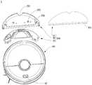
图1是本实用新型实施例的智能清洁设备的爆炸图;1 is an exploded view of an intelligent cleaning device according to an embodiment of the present invention;
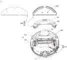
图2是本实用新型实施例的智能清洁设备的另一角度的爆炸图;2 is an exploded view of another angle of the smart cleaning device according to the embodiment of the present invention;
图3是本实用新型实施例的智能清洁设备的轴测图;Fig. 3 is the axonometric view of the intelligent cleaning device of the embodiment of the present invention;
图4是本实用新型实施例的智能清洁设备去掉柔性清洁体后的另一角度的轴测图;4 is an axonometric view of another angle after the flexible cleaning body is removed from the intelligent cleaning device according to the embodiment of the present utility model;
图5是本实用新型实施例的机器主体的轴测图;Fig. 5 is the axonometric view of the machine main body of the embodiment of the present invention;
图6是本实用新型实施例的托板与水箱的连接结构的爆炸图;6 is an exploded view of the connection structure of the support plate and the water tank according to the embodiment of the present invention;
图7是本实用新型实施例的另一角度的托板与水箱的连接结构的爆炸图;7 is an exploded view of the connection structure of the support plate and the water tank from another angle of the embodiment of the present utility model;
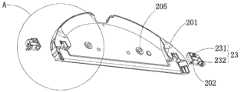
图8是本实用新型实施例的托板和设置于托板上的控制结构的连接结构的爆炸图;8 is an exploded view of the connection structure of the support plate and the control structure disposed on the support plate according to the embodiment of the present invention;
图9是图8中A位置的局部结构放大图;Fig. 9 is the partial structure enlarged view of A position in Fig. 8;
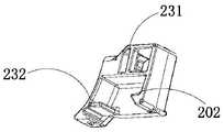
图10是本实用新型实施例的第二卡勾与控制结构的一体式结构的结构示意图;10 is a schematic structural diagram of an integrated structure of a second hook and a control structure according to an embodiment of the present invention;
图11是本实用新型实施例的托板和设置于托板上的控制结构的连接结构的结构示意图;11 is a schematic structural diagram of the connection structure of the support plate and the control structure disposed on the support plate according to the embodiment of the present invention;
图12是图11中B位置的局部结构放大图;Fig. 12 is a partial structure enlarged view of position B in Fig. 11;
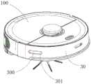
图13是本实用新型实施例的智能清洁设备的轴测图;13 is an axonometric view of an intelligent cleaning device according to an embodiment of the present invention;
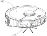
图14是本实用新型实施例的智能清洁设备去掉防护壳后的轴测图;14 is an axonometric view of the intelligent cleaning device according to the embodiment of the present invention after removing the protective shell;
图15是本实用新型实施例的镜片的轴测图;15 is an axonometric view of a lens of an embodiment of the present invention;
图16是本实用新型实施例的另一角度的镜片的轴测图。FIG. 16 is an axonometric view of a lens at another angle according to an embodiment of the present invention.
图中,In the figure,
1-智能清扫机器人;1-Intelligent cleaning robot;
100-机器主体;100 - the main body of the machine;
10-驱动系统;101-驱动轮模块;102-从动轮;10- drive system; 101- drive wheel module; 102- driven wheel;
11-悬崖传感器;11 - cliff sensor;
12-人机交互系统;12- Human-computer interaction system;
13-干式清洁部;131-滚刷;132-边刷;13-Dry cleaning section; 131-Rolling brush; 132-Side brush;
14-前向部分;14 - Forward part;
15-后向部分;15 - backward part;
16-风机安装位置;16- Fan installation position;
200-清洁组件;200 - cleaning components;
20-托板;201-导向凸起;202-第二卡勾;203-安装槽;204-豁口;205-弹性件;206-通水孔;207-安装口;20-support plate; 201-guide protrusion; 202-second hook; 203-installation slot; 204-gap; 205-elastic part; 206-water hole; 207-installation port;
21-清洁布;211-导向条;21-cleaning cloth; 211-guide strip;
22-水箱;221-导向槽;222-第一卡勾;22-water tank; 221-guide groove; 222-first hook;
23-控制结构;231-安装架;232-操作件;23-control structure; 231-mounting frame; 232-operating piece;
24-按钮;24 - button;
25-同程水路道板;251-出水口;25- Tongcheng waterway slab; 251- water outlet;
300-密封结构;300 - sealed structure;
30-防护壳;301-通孔;30-protective shell; 301-through hole;
31-镜片;311-弧形面板;3111-第一延伸板;312-第一连接板;3121-连接臂;3122-卡合孔;313-第二连接板;314-第三连接板;3141-第二延伸板;315-第四连接板。31-lens; 311-arc panel; 3111-first extension plate; 312-first connecting plate; 3121-connecting arm; 3122-engaging hole; 313-second connecting plate; 314-third connecting plate; - Second extension plate; 315 - Fourth connecting plate.
在附图中,相同的部件使用相同的附图标记。附图并未按照实际的比例绘制。In the drawings, the same components are given the same reference numerals. The drawings are not drawn to actual scale.
具体实施方式Detailed ways
下面将详细描述本实用新型的各个方面的特征和示例性实施例。在下面的详细描述中,提出了许多具体细节,以便提供对本实用新型的全面理解。但是,对于本领域技术人员来说很明显的是,本实用新型可以在不需要这些具体细节中的一些细节的情况下实施。下面对实施例的描述仅仅是为了通过示出本实用新型的示例来提供对本实用新型的更好的理解。在附图和下面的描述中,至少部分的公知结构和技术没有被示出,以便避免对本实用新型造成不必要的模糊;并且,为了清晰,可能夸大了部分结构的尺寸。此外,下文中所描述的特征、结构或特性可以以任何合适的方式结合在一个或更多实施例中。Features and exemplary embodiments of various aspects of the invention are described in detail below. In the following detailed description, numerous specific details are set forth in order to provide a thorough understanding of the present invention. However, it will be apparent to those skilled in the art that the present invention may be practiced without some of these specific details. The following description of the embodiments is merely to provide a better understanding of the present invention by illustrating examples of the present invention. In the drawings and the following description, at least some well-known structures and techniques are not shown in order to avoid unnecessarily obscuring the present invention; and, the dimensions of some structures may be exaggerated for clarity. Furthermore, the features, structures or characteristics described below may be combined in any suitable manner in one or more embodiments.
下述描述中出现的方位词均为图中示出的方向,并不是对本实用新型的密封结构300及智能清洁设备的具体结构进行限定。在本实用新型的描述中,还需要说明的是,除非另有明确的规定和限定,术语“安装”、“连接”应做广义理解,例如,可以是固定连接,也可以是可拆卸连接,或一体地连接;可以是直接相连,也可以间接相连。对于本领域的普通技术人员而言,可视具体情况理解上述术语在本实用新型中的具体含义。The orientation words appearing in the following description are all directions shown in the figures, and are not intended to limit the specific structures of the sealing
本实用新型实施例提供一种智能清洁设备,能够在每次更换柔性清洁体时,不需要拆卸液体容置箱,只需要沿着机器主体的前向或者后向方向拆卸连接板即可将柔性清洁体一并拆卸下来,方便操作的同时能够避免现有技术中的拆卸液体容置箱易造成的智能清洁设备的损坏。The embodiment of the present invention provides an intelligent cleaning device, which can remove the flexible cleaning body by removing the connecting plate along the forward or backward direction of the machine body without disassembling the liquid accommodating box each time the flexible cleaning body is replaced. The cleaning body is disassembled together, which is convenient for operation and can avoid damage to the intelligent cleaning equipment that is easily caused by disassembling the liquid accommodating box in the prior art.
为了更好地理解本实用新型,下面结合图1至12根据本实用新型实施例的智能清洁设备及清洁组件200进行详细描述。In order to better understand the present invention, the intelligent cleaning device and the cleaning
请参阅图1至图12,图1示出了本实用新型实施例的智能清洁设备的爆炸图;图2示出了本实用新型实施例的智能清洁设备的另一角度的爆炸图;图3示出了本实用新型实施例的智能清洁设备的轴测图;图4示出了本实用新型实施例的智能清洁设备的另一角度的轴测图;图5示出了本实用新型实施例的机器主体100的轴测图;图6示出了本实用新型实施例的托板20与水箱22的连接结构的爆炸图;图7示出了本实用新型实施例的另一角度的托板20与水箱22的连接结构的爆炸图;图8示出了本实用新型实施例的托板20和设置于托板20上的控制结构23的连接结构的爆炸图;图9示出了图8中A位置的局部结构放大图;图10示出了本实用新型实施例的第二卡勾202与控制结构23的一体式结构的结构示意图;图11示出了本实用新型实施例的托板20和设置于托板20上的控制结构23的连接结构的结构示意图;图12示出了图11中B位置的局部结构放大图。Please refer to FIGS. 1 to 12. FIG. 1 shows an exploded view of the smart cleaning device according to an embodiment of the present invention; FIG. 2 shows an exploded view from another angle of the smart cleaning device according to an embodiment of the present invention; FIG. 3 An axonometric view of the smart cleaning device according to an embodiment of the present invention is shown; FIG. 4 is an axonometric view from another angle of the smart cleaning device according to an embodiment of the present invention; and FIG. 5 shows an embodiment of the present invention. Figure 6 shows an exploded view of the connection structure of the supporting
名称定义:Name Definition:
前向:智能清洁设备的前进方向。Forward: The forward direction of the smart cleaning device.
后向:与智能清洁设备的前向相反的方向。Backward: The opposite direction to the forward direction of the smart cleaning device.
请参阅图1至图7,本实用新型实施例提供的智能清洁设备,包括机器主体100及清洁组件200,其中机器主体100用于承载智能清洁设备的各个功能部件,清洁组件200可拆卸地设置在机器主体100上,清洁组件200装入或拆出机器主体100时,清洁组件200可沿机器主体100的前向或后向方向移动。在一些可选的实施例中,清洁组件200包括层叠设置的液体容置箱、连接板和柔性清洁体,连接板通过导向结构安装于液体容置箱底部,当连接板被安装于液体容置箱底部后,连接板能够相对于液体容置箱上下浮动。在一些可选的实施例中,智能清洁设备为智能清扫机器人1,连接板为托板20,柔性清洁体为清洁布21,液体容置箱为水箱22。Referring to FIGS. 1 to 7 , the intelligent cleaning device provided by the embodiment of the present invention includes a
本实用新型实施例提供的智能清洁设备,在一些可选的实施例中,导向结构包括相互配合的导向凸起201和导向槽221,导向凸起201设置于托板20上,导向槽221设置于水箱22上;其中,导向凸起201的厚度小于导向槽221的槽厚,使得托板20被安装于水箱22底部后,托板20能够相对于水箱22上下浮动。可选的,导向凸起201的厚度具体指在智能清扫机器人1的高度方向上、导向凸起201的厚度,且导向槽221的槽厚是指在智能清扫机器人1的高度方向上、导向槽221的厚度。In the intelligent cleaning device provided by the embodiments of the present invention, in some optional embodiments, the guide structure includes guide
可以理解的是,导向结构并不限于上述结构形式,导向结构的具体结构也可以设置为:导向结构包括相互配合的导向凸起201和导向槽221,导向凸起201设置于水箱22上,导向槽221设置于托板20上;其中,导向凸起201的厚度小于导向槽221的槽厚,使得托板20被安装于水箱22底部后,托板20能够相对于水箱22上下浮动。导向凸起201的厚度具体指在智能清扫机器人1的高度方向上、导向凸起201的厚度,且导向槽221的槽厚也可以指在智能清扫机器人1的高度方向上、导向槽221的厚度。导向结构的结构设计只要能够满足水箱22和托板20的安装要求,并能够保证托板20能够沿着智能清扫机器人1的前向或后向方向移动即可。可选的,导向结构的设计还要满足当将托板20安装于水箱22上后,托板20能够相对于水箱22上下浮动。It can be understood that the guide structure is not limited to the above-mentioned structural form, and the specific structure of the guide structure can also be set as follows: the guide structure includes a
本实用新型实施例提供的智能清洁设备,清洁组件200整体可沿着智能清扫机器人1的前向或者后向方向从智能清扫机器人1的机器主体100上拆卸下来,托板20也可以沿着智能清扫机器人1的前向或者后向方向单独从智能清扫机器人1主体上拆卸下来,操作方便。In the intelligent cleaning device provided by the embodiment of the present invention, the cleaning
请进一步参阅图6及图7,本实用新型实施例提供的智能清洁设备,进一步地,托板20安装于水箱22上后,通过连接结构与水箱22相连接,连接结构包括相互配合的且分别设置于水箱22上的第一连接结构和设置于托板20上的第二连接结构。在一些可选的实施例中,第一连接结构为设置于水箱22上的第一卡勾222,第二连接结构为设置于托板20上的第二卡勾202,托板20通过导向结构安装于水箱22底部后,第一卡勾222和第二卡勾202能够相互卡合,使得托板20和水箱22连接稳固。Please further refer to FIG. 6 and FIG. 7 , in the intelligent cleaning device provided by the embodiment of the present invention, further, after the
请进一步参阅图8至图12,可选的,连接结构还包括控制结构23,控制结构23设置于托板20上,控制结构23能够控制第一卡勾222和第二卡勾202的连接和分离。在一些可选的实施例中,控制结构23与第二卡勾202为一体式结构,控制结构23包括:安装架231,安装架231可移动地设置于托板20上,第二卡勾202连接于安装架231的一端,以使第二卡勾202能够在安装架231的带动下移动至止挡位置或避让位置;操作件232,操作件232设置于安装架231的另一端,与第二卡勾202相对设置,以便于通过操作件232控制安装架231的移动。具体操作过程为:当向着智能清扫机器人1主体内部的方向按压操作件232时,整个控制结构23向着智能清扫机器人1主体内部的方向移动,此时第二卡勾202在控制结构23的带动下向着智能清扫机器人1主体内部的方向移动至避让位置,使得第一卡勾222和第二卡勾202分离,在第一卡勾222和第二卡勾202分离后,可以进一步沿着导向结构将托板20从水箱22上拆卸下来,操作方便。在更换完清洁布21后,重新将托板20安装至水箱22底部后,第二卡勾202在导向凸起201的限制下处于止挡位置,使得第一卡勾222和第二卡勾202相互连接,进一步使得水箱22和托板20稳固连接。Please refer to FIG. 8 to FIG. 12 , optionally, the connection structure further includes a
在一些可选的实施例中,导向凸起201设置于托板20上,且导向凸起201为弹性结构体,在第二卡勾202移动至避让位置时,导向凸起201能够在第二卡勾202的挤压下弹性变形,以使第一卡勾222与第二卡勾202分离,在第二卡勾202移动至止挡位置时,导向凸起201能够恢复至原始状态,以使第一卡勾222与第二卡勾202相连接。In some optional embodiments, the
可以理解的是,控制结构23可以但不限于上述结构形式,控制结构23还可以设置于水箱22上,且可选的,控制结构23可以与第一卡勾222为一体式结构,能够控制第一卡勾222和第二卡勾202的连接和分离。It can be understood that the
请参阅图1、图2及图12,本实用新型实施例提供的智能清洁设备,托板20和清洁布21通过滑动组件可拆卸连接,滑动组件包括相互配合的安装槽203和导向条211,在一些可选的实施例中,安装槽203设置于托板20上,导向条211设置于清洁布21上,导向条211可穿入安装槽203内以使清洁布21与托板20相连接,导向条211可从安装槽203内穿出以使清洁布21与托板20相分离,如此使得需要拆卸清洁布21时,可以直接将清洁布21从托板20上拆卸下来更换或者清洗,方便操作,同时也能够解决现有的智能清扫机器人1在更换清洁布21时需要将智能清扫机器人1翻转过来再将水箱22或者托板20一同拆下时,容易造成智能清扫机器人1的碰撞和损坏,还容易损坏智能清扫机器人1上的传感器,甚至容易造成智能清扫机器人1内部电路和部件损坏,产生不可修复的问题,进一步造成较大经济损失的技术问题。托板20与水箱22可拆卸连接,托板20装入或拆出机器主体100时,托板20沿机器主体100的前向或后向方向移动,将清洁布21连同托板20一同从智能清扫机器人1的水箱22上拆卸下来,由于清洁组件200的托板20在装配至水箱22上或者从水箱22上拆除时,托板20沿水箱22的前向方向或后向方向运动,而通常情况下水箱22的前向方向及后向方向为水平方向,所以使得带清洁布21的托板20的装入和拆卸更加方便,进一步解决了现有技术中需要将智能清扫机器人1翻转至底面朝上才能够拆卸清洁组件200的技术问题,这样使得清洁组件200的更换和维护更加方便。可以理解的是,智能清洁设备可以为但不限于智能清扫机器人1,在其他一些可选的实施例中,智能清洁设备还可以是太阳能电池板清洁装置或大楼外墙清洁装置等。Please refer to FIG. 1, FIG. 2 and FIG. 12. In the intelligent cleaning device provided by the embodiment of the present invention, the
可以理解的是,清洁组件200可以为并不限于上述结构形式,在其他一些可选的实施例中,安装槽203也可以设置于清洁布21上,导向条211也可以设置于托板20上,只要能够方便实现托板20和清洁布21的安装和拆卸即可。It can be understood that the cleaning
例如在如图1及图12所示的实施例中,安装槽203设置于托板20的远离机器主体100的一侧的一端端部,导向条211设置于清洁布21上与安装槽203相对应的位置,也即清洁布21的端部。但可以理解的是,在其他一些可选的实施例中,安装槽203也可以设置于托板20的远离机器主体100的一侧的中部位置,相应的,导向条211在清洁布21上的位置与安装槽203相对应,也设置于清洁布21的中部位置。For example, in the embodiment shown in FIG. 1 and FIG. 12 , the
本实用新型实施例提供的智能清洁设备,托板20上的安装槽203一端为安装端,另一端为止挡端,导向条211可通过安装端穿入或穿出安装槽203,并且通过止挡端限制导向条211由止挡端穿出安装槽203。In the intelligent cleaning device provided by the embodiment of the present invention, one end of the
在一些可选的实施例中,导向条211可以是具有一定刚度的塑料杆或钢制杆等,也可以是柔性的条状物。导向条211的横截面形状可以为圆形或非圆的其他形状。托板20上的安装槽203的横截面形状为C型或与C型相似的形状,只要保证能够容纳并限定导向条211即可。安装槽203的供清洁布21伸出的开口朝下,即C型的开口朝下,安装槽203的一端为伸入端,该伸入端不具有止挡结构,以供导向条211伸入,另一端为止挡端,该止挡端具有止挡结构,以防止导向条211从此端脱出。换而言之,安装槽203的一端封闭,另一端为开口。清洁布21的尾部通过导向条211与安装槽203配合的方式,固定在托板20上,提高了固定的稳定性,防止清洁布21脱落。该导向条211和安装槽203位于托板20上朝向智能清扫机器人1前向的方向上。通过这种先安装导向条211,再将清洁布21粘在魔术贴上的方式,确保清洁布21安装正确。In some optional embodiments, the
请进一步参阅图1及图2,清洁布21可以是整体为同一材质的清洁布21,也可以是不同位置采用不同材质的复合式清洁布21。在一些可选的实施例中,清洁布21为复合式清洁布21,该清洁布21主体基本上呈半圆形,其内层为渗水区,选用渗水率较高的材质;中间层为去污区,采用较为硬质的材料,用于刮去地面较硬物质;外层为吸水区,用于吸收底面的水分,去除水渍水痕,采用吸水效果较好的材料。这样可以提高清洁效率。导向条211设置在半圆形的直线段上。Please refer to FIG. 1 and FIG. 2 further, the cleaning
请进一步参阅图5及图6,本实用新型实施例提供的智能清洁设备,托板20上设置有通水孔206,用于将水箱22的水连通至清洁布21上。在一些可选的实施例中,水箱22可以为设置有蠕动泵的电控水箱22,智能清扫机器人1内部设置水路道板,可选的,水路道板为同程水路道板25,同程水路道板25设置于机器主体100与托板20之间,其与机器主体100可拆卸连接,且同程水路道板25上设置有进水口和出水口251,进水口与水箱22内部的蠕动泵的出水管道相连接,出水口251的位置与托板20上的通水孔206位对应设置,以便于水箱22的水经由同程水路道板25的出水口251和托板20上的通水孔206流至清洁布21上。Please further refer to FIG. 5 and FIG. 6 , in the intelligent cleaning device provided by the embodiment of the present invention, the
请进一步参阅图1及图2,本实用新型实施例提供的智能清洁设备,水箱22与机器主体100的对接位置形状对应设置,将水箱22安装于机器主体100上后,水箱22的外侧壁与机器主体100的侧壁相对接,水箱22的水箱底壁与机器主体100的底壁相对接,且水箱22至少部分包围在机器主体100内的风机的外侧,如图2所示,风机设置于风机安装位置16内部,在一些可选的实施例中,水箱22可以通过按钮24实现与机器主体100的连接和分离,托板20上设置有用于避让按钮24的豁口204,具体的,豁口204为设置于托板20顶部的与按钮24的外形相匹配的豁口204,需要将清洁组件200从机器主体100上拆卸下来时,按住按钮24即可实现清洁组件200与机器主体100的分离。Please refer to FIG. 1 and FIG. 2 further. In the intelligent cleaning device provided by the embodiment of the present invention, the shape of the docking position of the
请进一步参阅图6,本实用新型实施例提供的智能清洁设备,在一些可选的实施例中,托板20上面向水箱22的一侧表面上设置有弹性件205,当托板20被安装在水箱22上后,使托板20和水箱22之间为弹性接触,能够使得水箱22的上下浮动较为平稳,且托板20上的弹性件205抵触水箱22底面,使得工作时,托板20和地面之间产生压紧力,能够进一步使清洁布21和地面更加贴合,达到更好的清洁效果。可选的,弹性件205包括多个间隔设置于挡板面向水箱22的一侧表面的弹性纽扣,弹性纽扣内部均设置弹簧。Referring further to FIG. 6 , in the intelligent cleaning device provided by the embodiment of the present invention, in some optional embodiments, an
可以理解的是,弹性件205可以但不限于为上述结构,弹性件205也可以设置于水箱22面向托板20的一侧表面上,弹性件205包括多个间隔设置于水箱22面向托板20的一侧表面的弹性纽扣。当然,水箱22面向托板20的一侧表面上和托板20上面向水箱22的一侧表面上也可以同时设置弹性件205,当托板20被安装在水箱22上后,使托板20和水箱22之间为弹性接触。当水箱22面向托板20的一侧表面和托板20面向水箱22的一侧表面上同时设置弹性件205时,较为优选的,设置于水箱22面向托板20的一侧表面的弹性件205和设置于托板20面向水箱22的一侧表面的弹性件205错位设置,以进一步使得水箱22和托板20件达到更优的弹性接触效果。It can be understood that the
请进一步参阅图1及图2,本实用新型实施例提供的智能清洁设备,在一些可选的实施例中,机器主体100包括感知系统(图中未示出)、控制系统(图中未示出)、驱动系统10、能源系统、人机交互系统及干式清洁部13等。下面将对智能清洁设备的各主要部分进行说明。Please further refer to FIG. 1 and FIG. 2 , in the intelligent cleaning device provided by the embodiment of the present invention, in some optional embodiments, the
在一些可选的实施例中,机器主体100还包括上封盖、前向部分、后向部分和底盘等。机器主体100具有近似圆形形状,也可以为其他形状,包括但不限于前方后圆的近似D形形状。In some optional embodiments, the
感知系统包括位于机器主体100上方的位置确定装置、位于机器主体100的前向部分的缓冲器、悬崖传感器和超声传感器、红外传感器、磁力计、加速度计、陀螺仪、里程计等传感装置。这些传感装置向控制系统提供机器的各种位置信息和运动状态信息。位置确定装置包括但不限于红外发射接收装置、摄像头、激光测距装置(LDS)。The sensing system includes a position determination device located above the
驱动系统10用以驱动机器主体100及其上的部件移动,以进行自动行走和清扫。驱动系统10包括驱动轮模块101,驱动系统10可基于距离和角度信息,例如x、y及θ分量,发出驱动命令而操纵智能清扫机器人1跨越地面行驶。驱动轮模块101可以同时控制左轮和右轮,为了更为精确地控制机器的运动,优选驱动轮模块101分别包括左驱动轮模块和右驱动轮模块。左、右驱动轮模块沿着由机器主体100界定的横向轴对置,可选的,左、右驱动轮模块对称设置。为了智能清扫机器人1能够在地面上更为稳定地运动或者更强的运动能力,智能清扫机器人1可以包括一个或者多个从动轮102,从动轮包括但不限于万向轮。The driving
驱动轮模块101包括行走轮和驱动马达以及控制驱动马达的控制电路,驱动轮模块101还可以连接测量驱动电流的电路和里程计。驱动轮模块101可以可拆卸地连接到机器主体100上,方便拆装和维修。驱动轮可具有偏置下落式悬挂系统,以可移动方式紧固,例如以可旋转方式附接,到机器主体100上,且接受向下及远离机器主体100偏置的弹簧偏置。弹簧偏置允许驱动轮以一定的着地力维持与地面的接触及牵引,同时智能清扫机器人1的清洁元件(如滚刷131等)也以一定的压力接触地面。The
机器主体100的前向部分14可承载缓冲器,在清洁过程中驱动轮模块101推进智能清扫机器人1在地面行走时,缓冲器经由传感器系统,例如红外传感器,检测智能清扫机器人1的行驶路径中的一个或多个事件,智能清扫机器人1可通过由缓冲器检测到的事件,例如障碍物、墙壁,而控制驱动轮模块101使智能清扫机器人1来对事件做出响应,例如远离障碍物。The
控制系统设置在机器主体100内的电路主板上,包括与非暂时性存储器,例如硬盘、快闪存储器、随机存取存储器,通信的计算处理器,例如中央处理单元、应用处理器,应用处理器根据激光测距装置反馈的障碍物信息利用定位算法,例如SLAM,绘制智能清扫机器人1所在环境中的即时地图。并且结合缓冲器、悬崖传感器11和超声传感器、红外传感器、磁力计、加速度计、陀螺仪、里程计等传感装置反馈的距离信息、速度信息综合判断扫地机当前处于何种工作状态,如过门槛,上地毯,位于悬崖处,上方或者下方被卡住,尘盒满,被拿起等等,还会针对不同情况给出具体的下一步动作策略,使得智能清扫机器人1的工作更加符合主人的要求,有更好的用户体验。进一步地,控制系统能基于SLAM绘制的即时地图信息规划最为高效合理的清扫路径和清扫方式,大大提高智能清扫机器人1的清扫效率。The control system is arranged on the circuit board in the
能源系统包括充电电池,例如镍氢电池和锂电池。充电电池可以连接有充电控制电路、电池组充电温度检测电路和电池欠压监测电路,充电控制电路、电池组充电温度检测电路、电池欠压监测电路再与单片机控制电路相连。主机通过设置在机身侧方或者下方的充电电极与充电桩连接进行充电。如果裸露的充电电极上沾附有灰尘,会在充电过程中由于电荷的累积效应,导致电极周边的塑料机体融化变形,甚至导致电极本身发生变形,无法继续正常充电。The energy system includes rechargeable batteries such as NiMH and Lithium batteries. The rechargeable battery can be connected with a charging control circuit, a battery pack charging temperature detection circuit and a battery undervoltage monitoring circuit, and the charging control circuit, the battery pack charging temperature detection circuit, and the battery undervoltage monitoring circuit are then connected with the single-chip microcomputer control circuit. The host is charged by connecting to the charging pile through the charging electrode arranged on the side or below of the fuselage. If there is dust on the bare charging electrode, the plastic body around the electrode will melt and deform due to the accumulation effect of the charge during the charging process, and even the electrode itself will be deformed, making it impossible to continue normal charging.
人机交互系统12包括主机面板上的按键,按键供用户进行功能选择;还可以包括显示屏和/或指示灯和/或喇叭,显示屏、指示灯和喇叭向用户展示当前机器所处状态或者功能选择项;还可以包括手机客户端程序。对于路径导航型清洁设备,在手机客户端可以向用户展示设备所在环境的地图,以及机器所处位置,可以向用户提供更为丰富和人性化的功能项。The human-
请进一步参阅图3,为了更加清楚地描述智能清扫机器人1的行为,进行如下方向定义:智能清扫机器人1可通过相对于由机器主体100界定的如下三个相互垂直轴的移动的各种组合在地面上行进:前后轴X(即沿机器主体100的前向部分14和后向部分15方向的轴线)、横向轴Y(即垂直于轴X且与轴X在同一水平面的轴)及中心垂直轴Z(垂直于轴X和轴Y所组成的平面的轴)。沿着前后轴X的前向驱动方向标示为“前向”,且沿着前后轴X的向后驱动方向标示为“后向”。横向轴Y实质上是沿着由驱动轮模块101的中心点界定的轴心在智能清扫机器人1的右轮与左轮之间延伸。Referring further to FIG. 3 , in order to describe the behavior of the
智能清扫机器人1可以绕Y轴转动。当智能清扫机器人1的前向部分向上倾斜,向后向部分向下倾斜时为“上仰”,且当智能清扫机器人1的前向部分向下倾斜,向后向部分向上倾斜时为“下俯”。另外,智能清扫机器人1可以绕Z轴转动。在智能清扫机器人1的前向方向上,当智能清扫机器人1向X轴的右侧倾斜为“右转”,当智能清扫机器人1向X轴的左侧倾斜为“左转”。The
尘盒以机械抠手卡接的方式将尘盒安装在容纳腔中,抠手被抠住时卡件收缩,抠手放开时卡件伸出卡在容纳腔中容纳卡件的凹槽中。The dust box is installed in the accommodating cavity in the way of mechanically picking up the hand. When the hand is picked up, the clip shrinks, and when the hand is released, the clip protrudes and gets stuck in the groove of the accommodating clip in the accommodating cavity. .
上述清洁组件200作为智能清扫机器人1的湿式清洁部,其主要作用是通过含有清洁液的清洁布21对被清洁表面(如地面)进行擦拭。而干式清洁部13的主要作用是通过清扫刷等结构清扫被清洁表面的固定颗粒污染物。干式清洁部13的主要清洁功能源于滚刷131、尘盒、风机、出风口以及四者之间的连接部件所构成的第二清洁部。与地面具有一定干涉的滚刷131将地面上的垃圾扫起并卷带到滚刷131与尘盒之间的吸尘口前方,然后被风机产生并经过尘盒的有吸力的气体吸入尘盒。智能清扫机器人1的除尘能力可用垃圾的清扫效率DPU(Dust pick up efficiency)进行表征,清扫效率DPU受滚刷131结构和材料影响,受吸尘口、尘盒、风机、出风口以及四者之间的连接部件所构成的风道的风力利用率影响,受风机的类型和功率影响。相比于普通的插电吸尘器,除尘能力的提高对于能源有限的清洁智能清扫机器人1来说意义更大。因为除尘能力的提高直接有效降低了对于能源要求,也就是说原来充一次电可以清扫80平米地面的智能清扫机器人1,可以进化为充一次电清扫100平米甚至更多。并且减少充电次数的电池的使用寿命也会大大增加,使得用户更换电池的频率也会增加。更为直观和重要的是,除尘能力的提高是最为明显和重要的用户体验,用户会直接得出扫得是否干净/擦得是否干净的结论。干式清洁组件200还可包含具有旋转轴的边刷132,旋转轴相对于地面成一定角度,以用于将碎屑移动到第二清洁部的滚刷131的清扫区域中。The above-mentioned
本实用新型实施例还提供一种密封结构300,能够对红外沿墙模组实现较好的密封效果,且具有较好的防尘效果,使得灰尘不容易进入红外沿墙模组,对红外沿墙模组具有较好的保护作用。The embodiment of the present invention also provides a sealing
为了更好地理解本实用新型,下面结合图13至图16根据本实用新型实施例的密封结构300进行详细描述。For a better understanding of the present invention, the following describes the sealing
请参阅图13至图16,图13示出了本实用新型实施例的智能清洁设备的轴测图;图14示出了本实用新型实施例的智能清洁设备去掉防护壳30后的轴测图;图15示出了本实用新型实施例的镜片31的轴测图;图16示出了本实用新型实施例的另一角度的镜片的轴测图。Please refer to FIGS. 13 to 16 , FIG. 13 shows an axonometric view of the smart cleaning device according to an embodiment of the present invention; FIG. 14 shows an axonometric view of the smart cleaning device according to an embodiment of the present invention after removing the
请参阅图13至图16,本实用新型实施例提供的一种密封结构300,用于密封智能清洁设备的红外沿墙模组,包括壳体(图中未示出)和镜片31,壳体连接于红外沿墙模组面向智能清洁设备的防护壳30的一侧;镜片31与壳体相连接,镜片31包覆于壳体面向防护壳30的一侧表面,镜片31包括弧形面板311及设置于弧形面板311的边缘部位且朝向红外沿墙模组方向延伸的连接板。可选的,镜片31为透明镜片,进一步可以为玻璃片。该壳体为与镜片31相适配的结构,在此对其具体结构不予赘述。Referring to FIGS. 13 to 16 , a sealing
本实用新型实施例提供的密封结构300,壳体与镜片31通过卡合结构相连接,卡合结构包括相互配合的卡合扣和卡合孔3122,卡合扣设置于壳体和镜片31中的其中一者上,卡合孔3122设置于壳体和镜片31中的另一者上。In the sealing
本实用新型实施例提供的一种密封结构300,至少部分连接板上设置有连接臂3121,卡合孔3122设置于连接臂3121的远离弧形面板311的一端;其中,卡合扣设置于壳体上与卡合孔3122相对应的位置,以实现壳体与镜片31的连接。In the sealing
请进一步参阅参阅图15及图16,本实用新型实施例提供的密封结构300,在一些可选的实施例中,弧形面板311可以由矩形面板弯曲后得到,该弧形面板311具有四个外边缘,相应的,连接板为四个,四个连接板分别由弧形面板311的四个外边缘延伸出,且由弧形面板311的两个长边延伸出的两个连接板相对设置,具体的,由弧形面板311的两个长边延伸出的两个连接板分别为第一连接板312和第二连接板313,第一连接板312上设置有两个连接臂3121,两个连接臂3121沿第一连接板312的长度方向间隔设置,两个连接臂3121分别设置于第一连接板312的两端,且各连接臂3121上远离弧形面板311的一端均设置卡合孔3122;第二连接板313上设置有三个连接臂3121,三个连接臂3121沿第一连接板312的长度方向间隔设置,且其中两个连接臂3121分别设置于第二连接板313的两端,另一个连接臂3121设置于第二连接板313的中部,且各连接臂3121上远离弧形面板311的一端均设置卡合孔3122,可选的,卡合孔3122为在连接臂3121的厚度方向上贯通连接臂3121的条形通孔结构。15 and 16, the sealing
本实用新型实施例提供的密封结构300,在一些可选的实施例中,壳体上与卡合孔3122相对应的位置均设置卡合扣(图中未示出),在镜片31安装至壳体上时,卡合扣能够置于卡合孔3122内,以实现壳体与镜片31的连接。In the sealing
本实用新型实施例提供的密封结构300,在一些可选的实施例中,进一步包括至少一个由弧形面板311延伸出的第一延伸板3111,延伸板与弧形面板311平滑过渡连接。且密封结构300进一步包括至少一个由连接板朝向远离弧形面板311的方向延伸出的第二延伸板3141,第二延伸板3141与连接板相交设置。In some optional embodiments, the sealing
可选的,第一延伸板3111由弧形面板311上设置第一连接板312和第二连接板313的一侧延伸出,且延伸的宽度为弧形面板311的宽度的三分之一至四分之三,第一延伸板3111的设置可以进一步加强密封结构300对红外沿墙模组的保护作用,在不利条件下,灰尘即使与镜片31直接接触,也不会直接进入红外沿墙模组,而是使部分灰尘附着于第一延伸板3111上,而避免灰尘进入红外沿墙模组。Optionally, the
可选的,由弧形面板311的两个短边延伸出的两个连接板分别为第三连接板314和第四连接板315,第二延伸板3141为两个,两个第二延伸板3141各自由第三连接板314和第四连接板315延伸出,且分别与第三连接板314和第四连接板315相交设置,较为优选的,第二延伸板3141与第三连接板314和第四连接板315的夹角均为直角或者近似直角。同理,第二延伸板3141的设置可以进一步加强密封结构300对红外沿墙模组的保护作用,在不利条件下,灰尘即使与镜片31直接接触,也不会直接进入红外沿墙模组,而是使部分灰尘附着于第二延伸板3141上,而避免灰尘进入红外沿墙模组。Optionally, the two connecting plates extending from the two short sides of the arc-shaped
可以理解的是,密封结构300可以但不限于为上述具体结构,例如,密封结构300可以仅具有第一连接板312、第二连接板313、第三连接板314及第四连接板315中的至少其中一个。第一延伸板3111也可以设置为四个,四个第一延伸板3111分别由弧形面板311的四个外边缘延伸出,第二延伸板3141也可以为两个、三个或四个,本申请对此不作具体限制。It can be understood that the sealing
本实用新型实施例提供的密封结构300,在一些可选的实施例中,壳体包括相互配合的上壳和下壳,上壳与下壳可拆卸连接(图中未示出)。智能清洁设备的防护壳30设置于密封结构300外侧,且与机器主体100配合连接,用于防护机器主体100。具体的,防护壳30为近似半圆弧板的结构,其对应机器主体的前向部分15设置,防护壳30上与弧形面板311相对应的位置设置通孔301,在智能清洁设备使用一段时间后,镜片31上附着灰尘,能够通过通孔301直接对灰尘进行清理,方便操作,且便于将灰尘清理干净。In the sealing
本实用新型实施例提供的密封结构300,在一些可选的实施例中,镜片31面向防护壳30的一侧表面与防护壳30的内壁紧密贴合。在镜片31与防护壳30紧密贴合设置时,使得镜片31与防护壳30之间不具有间隙,在一定程度上使得灰尘只能附着于通过防护壳30上的通孔301暴露的镜片31部位,进一步避免灰尘进入红外沿墙模组,也进一步便于对灰尘的清理。In the sealing
虽然已经参考可选择的实施例对本实用新型进行了描述,但在不脱离本实用新型的范围的情况下,可以对其进行各种改进并且可以用等效物替换其特征在于的部件。尤其是,只要不存在结构冲突,各个实施例中所提到的各项技术特征均可以任意方式组合起来。本实用新型并不局限于文中公开的特定实施例,而是包括落入权利要求的范围内的所有技术方案。While the invention has been described with reference to alternative embodiments, various modifications may be made and equivalents may be substituted for the features it features without departing from the scope of the invention. In particular, as long as there is no structural conflict, each technical feature mentioned in each embodiment can be combined in any manner. The present invention is not limited to the specific embodiments disclosed herein, but includes all technical solutions falling within the scope of the claims.
Claims (10)
Translated fromChinesePriority Applications (6)
| Application Number | Priority Date | Filing Date | Title |
|---|---|---|---|
| CN201921473122.7UCN210931221U (en) | 2019-09-05 | 2019-09-05 | Sealing structure and intelligent cleaning equipment |
| US17/640,798US20220330775A1 (en) | 2019-09-05 | 2020-08-13 | Sealing structure and smart cleaning apparatus |
| ES20860214TES3000589T3 (en) | 2019-09-05 | 2020-08-13 | Sealing structure and smart cleaning apparatus |
| PCT/CN2020/108902WO2021042959A1 (en) | 2019-09-05 | 2020-08-13 | Sealing structure and smart cleaning apparatus |
| PL20860214.4TPL4011266T3 (en) | 2019-09-05 | 2020-08-13 | Sealing structure and smart cleaning apparatus |
| EP20860214.4AEP4011266B1 (en) | 2019-09-05 | 2020-08-13 | Sealing structure and smart cleaning apparatus |
Applications Claiming Priority (1)
| Application Number | Priority Date | Filing Date | Title |
|---|---|---|---|
| CN201921473122.7UCN210931221U (en) | 2019-09-05 | 2019-09-05 | Sealing structure and intelligent cleaning equipment |
Publications (1)
| Publication Number | Publication Date |
|---|---|
| CN210931221Utrue CN210931221U (en) | 2020-07-07 |
Family
ID=71387434
Family Applications (1)
| Application Number | Title | Priority Date | Filing Date |
|---|---|---|---|
| CN201921473122.7UActiveCN210931221U (en) | 2019-09-05 | 2019-09-05 | Sealing structure and intelligent cleaning equipment |
Country Status (6)
| Country | Link |
|---|---|
| US (1) | US20220330775A1 (en) |
| EP (1) | EP4011266B1 (en) |
| CN (1) | CN210931221U (en) |
| ES (1) | ES3000589T3 (en) |
| PL (1) | PL4011266T3 (en) |
| WO (1) | WO2021042959A1 (en) |
Cited By (3)
| Publication number | Priority date | Publication date | Assignee | Title |
|---|---|---|---|---|
| WO2021042959A1 (en)* | 2019-09-05 | 2021-03-11 | 北京石头世纪科技股份有限公司 | Sealing structure and smart cleaning apparatus |
| CN113100671A (en)* | 2021-04-27 | 2021-07-13 | 深圳乐生机器人智能科技有限公司 | Cleaning assembly for floor sweeping robot and floor sweeping robot |
| WO2023174105A1 (en)* | 2022-03-16 | 2023-09-21 | 北京赫特智慧科技有限公司 | Housing module and cleaning device |
Families Citing this family (10)
| Publication number | Priority date | Publication date | Assignee | Title |
|---|---|---|---|---|
| USD1003550S1 (en)* | 2020-09-03 | 2023-10-31 | Sharkninja Operating Llc | Robot vacuum wet module |
| CA207237S (en)* | 2021-02-10 | 2022-08-05 | Beijing Roborock Technology Co Ltd | Supporting plate for cleaning pad for robotic vacuum cleaner |
| USD1000741S1 (en)* | 2021-02-10 | 2023-10-03 | Beijing Roborock Technology Co., Ltd. | Water tank for a cleaning robot |
| USD990802S1 (en)* | 2021-08-05 | 2023-06-27 | Shenzhen Haitao Optimization Technology Co., Ltd. | Sweeping robot |
| USD998922S1 (en)* | 2021-08-23 | 2023-09-12 | Beijing Roborock Technology Co., Ltd. | Water tank for a cleaning robot |
| USD1010259S1 (en)* | 2022-02-09 | 2024-01-02 | Beijing Roborock Technology Co., Ltd. | Mop component for a robotic vacuum cleaner |
| TWD231050S (en)* | 2023-02-28 | 2024-05-01 | 大陸商北京石頭世紀科技股份有限公司 (中國大陸) | Cleaning robot |
| JP1788034S (en) | 2023-03-15 | 2024-12-27 | Cleaning pad for mobile cleaning robot | |
| USD1049528S1 (en)* | 2023-03-29 | 2024-10-29 | Irobot Corporation | Cleaning pad for use in a mobile cleaning robot |
| USD1082190S1 (en)* | 2023-06-12 | 2025-07-01 | Samsung Electronics Co., Ltd. | Robot vacuum cleaner |
Family Cites Families (11)
| Publication number | Priority date | Publication date | Assignee | Title |
|---|---|---|---|---|
| KR100711972B1 (en)* | 2004-12-08 | 2007-05-02 | 주식회사 유진로봇 | Cleaning robot and its cleaning method |
| US9144360B2 (en)* | 2005-12-02 | 2015-09-29 | Irobot Corporation | Autonomous coverage robot navigation system |
| CN104248395B (en)* | 2008-04-24 | 2018-06-22 | 艾罗伯特公司 | The positioning of mobile product, position control and the application of navigation system enabled for robot |
| WO2016021111A1 (en)* | 2014-08-07 | 2016-02-11 | パナソニックIpマネジメント株式会社 | Resin structure and electric vacuum cleaner using same |
| CN205697554U (en)* | 2015-10-17 | 2016-11-23 | 胡永纲 | A kind of Crashworthy plate mechanism of intelligent sweeping |
| CN105615778B (en)* | 2016-01-22 | 2017-12-22 | 杭州信多达电器有限公司 | Sweeper with infrared camera shooting function |
| US10575696B2 (en)* | 2016-07-13 | 2020-03-03 | Irobot Corporation | Autonomous robot auto-docking and energy management systems and methods |
| JP6831213B2 (en)* | 2016-11-09 | 2021-02-17 | 東芝ライフスタイル株式会社 | Vacuum cleaner |
| CN108903848B (en)* | 2018-08-28 | 2021-11-30 | 深圳市无限动力发展有限公司 | Protection component and robot of sweeping floor |
| CN109124496B (en)* | 2018-09-20 | 2023-11-28 | 小狗电器互联网科技(北京)股份有限公司 | Sweeping robot and cleaning equipment |
| CN210931221U (en)* | 2019-09-05 | 2020-07-07 | 北京石头世纪科技股份有限公司 | Sealing structure and intelligent cleaning equipment |
- 2019
- 2019-09-05CNCN201921473122.7Upatent/CN210931221U/enactiveActive
- 2020
- 2020-08-13USUS17/640,798patent/US20220330775A1/enactivePending
- 2020-08-13PLPL20860214.4Tpatent/PL4011266T3/enunknown
- 2020-08-13EPEP20860214.4Apatent/EP4011266B1/enactiveActive
- 2020-08-13ESES20860214Tpatent/ES3000589T3/enactiveActive
- 2020-08-13WOPCT/CN2020/108902patent/WO2021042959A1/ennot_activeCeased
Cited By (3)
| Publication number | Priority date | Publication date | Assignee | Title |
|---|---|---|---|---|
| WO2021042959A1 (en)* | 2019-09-05 | 2021-03-11 | 北京石头世纪科技股份有限公司 | Sealing structure and smart cleaning apparatus |
| CN113100671A (en)* | 2021-04-27 | 2021-07-13 | 深圳乐生机器人智能科技有限公司 | Cleaning assembly for floor sweeping robot and floor sweeping robot |
| WO2023174105A1 (en)* | 2022-03-16 | 2023-09-21 | 北京赫特智慧科技有限公司 | Housing module and cleaning device |
Also Published As
| Publication number | Publication date |
|---|---|
| EP4011266A4 (en) | 2023-08-23 |
| PL4011266T3 (en) | 2025-02-24 |
| ES3000589T3 (en) | 2025-02-28 |
| US20220330775A1 (en) | 2022-10-20 |
| WO2021042959A1 (en) | 2021-03-11 |
| EP4011266A1 (en) | 2022-06-15 |
| EP4011266B1 (en) | 2024-10-02 |
Similar Documents
| Publication | Publication Date | Title |
|---|---|---|
| CN210931221U (en) | Sealing structure and intelligent cleaning equipment | |
| TWI789624B (en) | Smart cleaning device | |
| US11653806B2 (en) | Autonomous cleaning robot | |
| CN210931186U (en) | Seal and block up and intelligent cleaning equipment | |
| TWI769511B (en) | Cleaning assembly and intelligent cleaning device | |
| US11659972B2 (en) | Moisture-proof mat and intelligent cleaning system | |
| CN210931185U (en) | A smart cleaning device | |
| CN210931184U (en) | Cleaning assembly and intelligent cleaning equipment | |
| CN114587177A (en) | Automatic cleaning equipment | |
| CN219895618U (en) | Base station and cleaning robot system | |
| US12440081B2 (en) | Cleaning assembly and smart cleaning device |
Legal Events
| Date | Code | Title | Description |
|---|---|---|---|
| GR01 | Patent grant | ||
| GR01 | Patent grant |