CN210927937U - Terminal equipment, wireless headsets and electronic equipment components - Google Patents
Terminal equipment, wireless headsets and electronic equipment componentsDownload PDFInfo
- Publication number
- CN210927937U CN210927937UCN201921568931.6UCN201921568931UCN210927937UCN 210927937 UCN210927937 UCN 210927937UCN 201921568931 UCN201921568931 UCN 201921568931UCN 210927937 UCN210927937 UCN 210927937U
- Authority
- CN
- China
- Prior art keywords
- earphone
- terminal device
- wireless
- wireless earphone
- magnetic attraction
- Prior art date
- Legal status (The legal status is an assumption and is not a legal conclusion. Google has not performed a legal analysis and makes no representation as to the accuracy of the status listed.)
- Active
Links
Images


Classifications
- H—ELECTRICITY
- H04—ELECTRIC COMMUNICATION TECHNIQUE
- H04M—TELEPHONIC COMMUNICATION
- H04M1/00—Substation equipment, e.g. for use by subscribers
- H04M1/02—Constructional features of telephone sets
- H04M1/0202—Portable telephone sets, e.g. cordless phones, mobile phones or bar type handsets
- H04M1/0254—Portable telephone sets, e.g. cordless phones, mobile phones or bar type handsets comprising one or a plurality of mechanically detachable modules
- H04M1/0258—Portable telephone sets, e.g. cordless phones, mobile phones or bar type handsets comprising one or a plurality of mechanically detachable modules for a headset device
- H—ELECTRICITY
- H04—ELECTRIC COMMUNICATION TECHNIQUE
- H04R—LOUDSPEAKERS, MICROPHONES, GRAMOPHONE PICK-UPS OR LIKE ACOUSTIC ELECTROMECHANICAL TRANSDUCERS; DEAF-AID SETS; PUBLIC ADDRESS SYSTEMS
- H04R1/00—Details of transducers, loudspeakers or microphones
- H04R1/10—Earpieces; Attachments therefor ; Earphones; Monophonic headphones
- H04R1/1041—Mechanical or electronic switches, or control elements
- H—ELECTRICITY
- H01—ELECTRIC ELEMENTS
- H01F—MAGNETS; INDUCTANCES; TRANSFORMERS; SELECTION OF MATERIALS FOR THEIR MAGNETIC PROPERTIES
- H01F7/00—Magnets
- H01F7/06—Electromagnets; Actuators including electromagnets
- H01F7/20—Electromagnets; Actuators including electromagnets without armatures
- H—ELECTRICITY
- H04—ELECTRIC COMMUNICATION TECHNIQUE
- H04M—TELEPHONIC COMMUNICATION
- H04M1/00—Substation equipment, e.g. for use by subscribers
- H04M1/02—Constructional features of telephone sets
- H04M1/04—Supports for telephone transmitters or receivers
- H04M1/05—Supports for telephone transmitters or receivers specially adapted for use on head, throat or breast
- H—ELECTRICITY
- H04—ELECTRIC COMMUNICATION TECHNIQUE
- H04R—LOUDSPEAKERS, MICROPHONES, GRAMOPHONE PICK-UPS OR LIKE ACOUSTIC ELECTROMECHANICAL TRANSDUCERS; DEAF-AID SETS; PUBLIC ADDRESS SYSTEMS
- H04R1/00—Details of transducers, loudspeakers or microphones
- H04R1/10—Earpieces; Attachments therefor ; Earphones; Monophonic headphones
- H04R1/1016—Earpieces of the intra-aural type
- H—ELECTRICITY
- H04—ELECTRIC COMMUNICATION TECHNIQUE
- H04R—LOUDSPEAKERS, MICROPHONES, GRAMOPHONE PICK-UPS OR LIKE ACOUSTIC ELECTROMECHANICAL TRANSDUCERS; DEAF-AID SETS; PUBLIC ADDRESS SYSTEMS
- H04R1/00—Details of transducers, loudspeakers or microphones
- H04R1/10—Earpieces; Attachments therefor ; Earphones; Monophonic headphones
- H04R1/1091—Details not provided for in groups H04R1/1008 - H04R1/1083
- H—ELECTRICITY
- H04—ELECTRIC COMMUNICATION TECHNIQUE
- H04M—TELEPHONIC COMMUNICATION
- H04M1/00—Substation equipment, e.g. for use by subscribers
- H04M1/60—Substation equipment, e.g. for use by subscribers including speech amplifiers
- H04M1/6033—Substation equipment, e.g. for use by subscribers including speech amplifiers for providing handsfree use or a loudspeaker mode in telephone sets
- H04M1/6041—Portable telephones adapted for handsfree use
- H04M1/6058—Portable telephones adapted for handsfree use involving the use of a headset accessory device connected to the portable telephone
- H04M1/6066—Portable telephones adapted for handsfree use involving the use of a headset accessory device connected to the portable telephone including a wireless connection
- H—ELECTRICITY
- H04—ELECTRIC COMMUNICATION TECHNIQUE
- H04R—LOUDSPEAKERS, MICROPHONES, GRAMOPHONE PICK-UPS OR LIKE ACOUSTIC ELECTROMECHANICAL TRANSDUCERS; DEAF-AID SETS; PUBLIC ADDRESS SYSTEMS
- H04R1/00—Details of transducers, loudspeakers or microphones
- H04R1/10—Earpieces; Attachments therefor ; Earphones; Monophonic headphones
- H04R1/1025—Accumulators or arrangements for charging
- H—ELECTRICITY
- H04—ELECTRIC COMMUNICATION TECHNIQUE
- H04R—LOUDSPEAKERS, MICROPHONES, GRAMOPHONE PICK-UPS OR LIKE ACOUSTIC ELECTROMECHANICAL TRANSDUCERS; DEAF-AID SETS; PUBLIC ADDRESS SYSTEMS
- H04R2201/00—Details of transducers, loudspeakers or microphones covered by H04R1/00 but not provided for in any of its subgroups
- H04R2201/10—Details of earpieces, attachments therefor, earphones or monophonic headphones covered by H04R1/10 but not provided for in any of its subgroups
- H04R2201/107—Monophonic and stereophonic headphones with microphone for two-way hands free communication
- H—ELECTRICITY
- H04—ELECTRIC COMMUNICATION TECHNIQUE
- H04R—LOUDSPEAKERS, MICROPHONES, GRAMOPHONE PICK-UPS OR LIKE ACOUSTIC ELECTROMECHANICAL TRANSDUCERS; DEAF-AID SETS; PUBLIC ADDRESS SYSTEMS
- H04R2420/00—Details of connection covered by H04R, not provided for in its groups
- H04R2420/07—Applications of wireless loudspeakers or wireless microphones
- H—ELECTRICITY
- H04—ELECTRIC COMMUNICATION TECHNIQUE
- H04R—LOUDSPEAKERS, MICROPHONES, GRAMOPHONE PICK-UPS OR LIKE ACOUSTIC ELECTROMECHANICAL TRANSDUCERS; DEAF-AID SETS; PUBLIC ADDRESS SYSTEMS
- H04R2499/00—Aspects covered by H04R or H04S not otherwise provided for in their subgroups
- H04R2499/10—General applications
- H04R2499/11—Transducers incorporated or for use in hand-held devices, e.g. mobile phones, PDA's, camera's
Landscapes
- Physics & Mathematics (AREA)
- Engineering & Computer Science (AREA)
- Signal Processing (AREA)
- Acoustics & Sound (AREA)
- Electromagnetism (AREA)
- Power Engineering (AREA)
- Health & Medical Sciences (AREA)
- Otolaryngology (AREA)
- Headphones And Earphones (AREA)
- Telephone Set Structure (AREA)
Abstract
Description
Translated fromChinese技术领域technical field
本公开涉及电子设备领域,尤其涉及一种终端设备、无线耳机及电子设备组件。The present disclosure relates to the field of electronic devices, and in particular, to a terminal device, a wireless headset and an electronic device assembly.
背景技术Background technique
终端设备具有声音外放功能或接听功能,可与无线耳机配合使用。无线耳机由于便捷性越来越得到用户的青睐,通常无线耳机配备有专门的收纳装置,但携带收纳装置造成不便、容易丢失等问题,不能提升用户体验。The terminal device has the function of sound playback or answering, and can be used in conjunction with wireless earphones. Wireless earphones are increasingly favored by users due to their convenience. Usually, wireless earphones are equipped with a special storage device, but carrying the storage device causes problems such as inconvenience and easy loss, which cannot improve the user experience.
实用新型内容Utility model content
本公开提供了一种改进的终端设备、无线耳机及电子设备组件。The present disclosure provides an improved terminal device, wireless headset and electronic device assembly.
本公开的一个方面提供一种终端设备,所述终端设备包括:An aspect of the present disclosure provides a terminal device, the terminal device comprising:
机身,设有收纳无线耳机的收纳槽;The fuselage is provided with a storage slot for storing wireless headphones;
磁吸组件,设于所述收纳槽内;及a magnetic attraction component, disposed in the receiving slot; and
第一控制器,设于所述机身内,与所述磁吸组件电连接,控制所述磁吸组件与所述无线耳机吸引连接或排斥分离。The first controller is arranged in the body and is electrically connected to the magnetic attraction component, and controls the magnetic attraction component to be connected to or repulsed from the wireless earphone.
可选地,所述收纳槽包括凸出的限位台阶,所述限位台阶在所述收纳槽朝向耳机头的一侧设有所述磁吸组件。Optionally, the storage slot includes a protruding limit step, and the limit step is provided with the magnetic attraction component on a side of the storage slot facing the earphone head.
可选地,所述磁吸组件包括与所述第一控制器电连接的电磁铁,所述第一控制器控制所述电磁铁吸引或排斥所述无线耳机。Optionally, the magnetic attraction assembly includes an electromagnet electrically connected to the first controller, and the first controller controls the electromagnet to attract or repel the wireless earphone.
可选地,所述磁吸组件还包括吸引所述无线耳机的第一永磁体。Optionally, the magnetic attraction assembly further includes a first permanent magnet that attracts the wireless earphone.
可选地,所述终端设备还包括:收容于所述收纳槽内的弹性件,在所述无线耳机插入所述收纳槽内时,沿所述无线耳机插入方向弹性变形,且与所述无线耳机弹性相抵。Optionally, the terminal device further includes: an elastic member accommodated in the storage slot, when the wireless earphone is inserted into the storage slot, elastically deforms along the insertion direction of the wireless earphone, and is compatible with the wireless earphone. The earphones are elastically offset.
可选地,所述收纳槽的内壁设有凸出于所述内壁的第一触电点,所述第一触电点与所述无线耳机电连接时,所述第一控制器控制所述终端设备为所述无线耳机充电。Optionally, the inner wall of the storage slot is provided with a first electric contact point protruding from the inner wall, and when the first electric contact point is electrically connected with the wireless earphone, the first controller controls the terminal device Charge the wireless earphones.
可选地,所述收纳槽的数目为至少一个,收纳至少一个所述无线耳机。Optionally, the number of the storage slots is at least one, and at least one of the wireless earphones is stored.
本公开的另一个方面提供一种无线耳机,所述无线耳机可收纳于终端设备的收纳槽中,所述无线耳机包括:Another aspect of the present disclosure provides a wireless earphone, the wireless earphone can be stored in a storage slot of a terminal device, and the wireless earphone includes:
耳机本体;Headphone body;
耳机头,设于所述耳机本体的端部;及an earphone head, located at the end of the earphone body; and
磁吸件,设于所述耳机头,所述磁吸件与所述终端设备吸引连接或排斥分离。The magnetic attraction piece is arranged on the earphone head, and the magnetic attraction piece is connected with the terminal device by attraction or separation by repulsion.
可选地,所述耳机头的径向尺寸大于所述耳机本体的径向尺寸,所述磁吸件设于所述耳机头接近所述耳机本体的一侧。Optionally, the radial dimension of the earphone head is larger than the radial dimension of the earphone body, and the magnetic attraction member is provided on a side of the earphone head close to the earphone body.
可选地,所述磁吸件包括第二永磁体,与所述终端设备吸引连接。Optionally, the magnetic attraction piece includes a second permanent magnet, which is connected to the terminal device in an attractive manner.
可选地,所述耳机本体的外表面设有凹陷于所述外表面的第二触电点,与所述终端设备电连接。Optionally, the outer surface of the earphone body is provided with a second contact point recessed on the outer surface, and is electrically connected to the terminal device.
可选地,所述无线耳机包括设于所述耳机本体内的音频模组和第二控制器,所述音频模组与所述第二控制器电连接,所述第二触电点与所述终端设备电连接时,所述第二控制器控制所述音频模组的工作模式为扬声器模式。Optionally, the wireless earphone includes an audio module and a second controller arranged in the earphone body, the audio module is electrically connected to the second controller, and the second contact point is connected to the second controller. When the terminal device is electrically connected, the second controller controls the working mode of the audio module to be a speaker mode.
可选地,所述无线耳机的数目为至少一个,所述无线耳机在脱离所述收纳槽之后,与所述终端设备无线连接。Optionally, the number of the wireless earphones is at least one, and the wireless earphones are wirelessly connected to the terminal device after being detached from the storage slot.
可选地,所述耳机本体与所述耳机头可转动连接。Optionally, the earphone body and the earphone head are rotatably connected.
本公开的另一个方面提供一种电子设备组件,所述电子设备组件包括:上述提及的任一种所述的终端设备、以及上述提及的任一种所述的无线耳机。Another aspect of the present disclosure provides an electronic device assembly, the electronic device assembly comprising: any one of the aforementioned terminal devices, and any one of the aforementioned wireless headsets.
本公开实施例提供的终端设备、无线耳机及电子设备组件具有至少以下有益效果:The terminal device, wireless headset, and electronic device assembly provided by the embodiments of the present disclosure have at least the following beneficial effects:
本公开实施例提供的终端设备,通过收纳槽收纳无线耳机,避免为无线耳机配备专门的收纳装置,方便收纳。通过第一控制器控制磁吸组件与无线耳机吸引连接,以将无线耳机牢固地收纳于收纳槽内,避免丢失无线耳机,通过第一控制器控制磁吸组件与无线耳机排斥分离,方便从收纳槽中取出无线耳机。本公开实施例提供的无线耳机,可收纳于终端设备的收纳槽中,通过磁吸件与终端设备吸引连接,以牢固地收容于终端设备的收纳槽中,避免丢失。通过磁吸件与终端设备排斥分离,方便从收纳槽中取出无线耳机。本公开实施例提供的电子设备组件,无线耳机可牢固地收容于终端设备的收纳槽中,方便收纳,避免丢失,而且还方便将无线耳机从收纳槽中取出。In the terminal device provided by the embodiments of the present disclosure, the wireless earphone is stored in the storage slot, and a special storage device is avoided for the wireless earphone, which is convenient for storage. The first controller is used to control the magnetic attraction component to be connected with the wireless earphone to attract and connect, so that the wireless earphone can be securely stored in the storage slot to avoid losing the wireless earphone. Remove the wireless headset from the slot. The wireless earphone provided by the embodiment of the present disclosure can be stored in a storage slot of a terminal device, and is connected to the terminal device through a magnetic attraction, so as to be firmly stored in the storage slot of the terminal device to avoid loss. The magnetic attraction piece is repelled and separated from the terminal device, so that the wireless earphone can be conveniently taken out from the storage slot. In the electronic device assembly provided by the embodiment of the present disclosure, the wireless earphone can be firmly accommodated in the storage slot of the terminal device, which is convenient for storage and avoids loss, and also facilitates taking out the wireless earphone from the storage slot.
附图说明Description of drawings
图1所示为本公开根据一示例性实施例示出的电子设备组件的局部分解示意图;FIG. 1 shows a partial exploded schematic diagram of an electronic device assembly according to an exemplary embodiment of the present disclosure;
图2所示为本公开根据一示例性实施例示出的电子设备组件的局部剖视图;FIG. 2 shows a partial cross-sectional view of an electronic device assembly according to an exemplary embodiment of the present disclosure;
图3所示为本公开根据一示例性实施例示出的电子设备组件的局部放大示意图;FIG. 3 is a partial enlarged schematic diagram of an electronic device assembly shown in the present disclosure according to an exemplary embodiment;
图4所示为本公开根据一示例性实施例示出的电子设备组件的局部放大示意图;FIG. 4 is a partial enlarged schematic diagram of an electronic device assembly shown in the present disclosure according to an exemplary embodiment;
图5所示为本公开根据一示例性实施例示出的磁吸组件与磁吸件之间的磁性吸引示意图;FIG. 5 is a schematic diagram of the magnetic attraction between the magnetic attraction component and the magnetic attraction member according to an exemplary embodiment of the present disclosure;
图6所示为本公开根据一示例性实施例示出的电子设备组件的局部放大示意图;FIG. 6 is a partial enlarged schematic diagram of an electronic device assembly shown in the present disclosure according to an exemplary embodiment;
图7所示为本公开根据一示例性实施例示出的无线耳机的功能器件的控制示意图;FIG. 7 is a schematic control diagram of a functional device of a wireless headset according to an exemplary embodiment of the present disclosure;
图8所示为本公开根据一示例性实施例示出的与终端设备不同配合关系时无线耳机的工作示意图;FIG. 8 is a schematic diagram showing the operation of the wireless headset according to an exemplary embodiment of the present disclosure when the wireless headset is in a different cooperation relationship with the terminal device;
图9所示为本公开根据一示例性实施例示出的无线耳机与终端设备无线连接时的工作示意图;FIG. 9 is a schematic diagram showing the operation of the wireless headset when the wireless headset is wirelessly connected to a terminal device according to an exemplary embodiment of the present disclosure;
图10所示为本公开根据一示例性实施例示出的与终端设备不同配合关系时无线耳机的工作示意图;FIG. 10 is a schematic diagram showing the operation of the wireless headset according to an exemplary embodiment of the present disclosure when the wireless headset has different cooperation relationships with the terminal device;
图11所示为本公开根据一示例性实施例示出的无线耳机在被佩戴时的状态图;FIG. 11 shows a state diagram of the wireless headset according to an exemplary embodiment of the present disclosure when it is worn;
图12所示为本公开根据一示例性实施例示出的无线耳机在被收纳时的状态图。FIG. 12 shows a state diagram of the wireless headset according to an exemplary embodiment of the present disclosure when it is stored.
具体实施方式Detailed ways
这里将详细地对示例性实施例进行说明,其示例表示在附图中。下面的描述涉及附图时,除非另有表示,不同附图中的相同数字表示相同或相似的要素。以下示例性实施例中所描述的实施方式并不代表与本公开相一致的所有实施方式。相反,它们仅是与如所附权利要求书中所详述的、本公开的一些方面相一致的装置和方法的例子。Exemplary embodiments will be described in detail herein, examples of which are illustrated in the accompanying drawings. Where the following description refers to the drawings, the same numerals in different drawings refer to the same or similar elements unless otherwise indicated. The implementations described in the illustrative examples below are not intended to represent all implementations consistent with this disclosure. Rather, they are merely examples of apparatus and methods consistent with some aspects of the present disclosure as recited in the appended claims.
在本公开使用的术语是仅仅出于描述特定实施例的目的,而非旨在限制本公开。除非另作定义,本公开使用的技术术语或者科学术语应当为本公开所属领域内具有一般技能的人士所理解的通常意义。本公开说明书以及权利要求书中使用的“第一”“第二”以及类似的词语并不表示任何顺序、数量或者重要性,而只是用来区分不同的组成部分。同样,“一个”或者“一”等类似词语也不表示数量限制,而是表示存在至少一个。除非另行指出,“包括”或者“包含”等类似词语意指出现在“包括”或者“包含”前面的元件或者物件涵盖出现在“包括”或者“包含”后面列举的元件或者物件及其等同,并不排除其他元件或者物件。“连接”或者“相连”等类似的词语并非限定于物理的或者机械的连接,而且可以包括电性的连接,不管是直接的还是间接的。The terminology used in the present disclosure is for the purpose of describing particular embodiments only and is not intended to limit the present disclosure. Unless otherwise defined, technical or scientific terms used in this disclosure should have the ordinary meaning as understood by one of ordinary skill in the art to which this disclosure belongs. As used in this disclosure and in the claims, "first," "second," and similar terms do not denote any order, quantity, or importance, but are merely used to distinguish the various components. Likewise, "a" or "an" and the like do not denote a quantitative limitation, but rather denote the presence of at least one. Unless stated otherwise, words like "including" or "comprising" mean that the elements or items appearing before "including" or "including" encompass the elements or items listed after "including" or "including" and their equivalents, and Other elements or objects are not excluded. "Connected" or "connected" and similar words are not limited to physical or mechanical connections, but may include electrical connections, whether direct or indirect.
在本公开说明书和所附权利要求书中所使用的单数形式的“一种”、“所述”和“该”也旨在包括多数形式,除非上下文清楚地表示其他含义。还应当理解,本文中使用的术语“和/或”是指并包含一个或多个相关联的列出项目的任何或所有可能组合。As used in this disclosure and the appended claims, the singular forms "a," "the," and "the" are intended to include the plural forms as well, unless the context clearly dictates otherwise. It will also be understood that the term "and/or" as used herein refers to and includes any and all possible combinations of one or more of the associated listed items.
一些实施例中,终端设备设有收纳槽,无线耳机通过摩擦力收容于收纳槽内。但是在晃动终端设备时,无线耳机容易从收纳槽中跌落,终端设备不能牢固地收纳无线耳机。In some embodiments, the terminal device is provided with a storage slot, and the wireless earphone is stored in the storage slot by frictional force. However, when the terminal device is shaken, the wireless earphone is easily dropped from the storage slot, and the terminal device cannot securely store the wireless earphone.
为了解决上述问题,本公开实施例提供了一种终端设备、无线耳机及电子设备组件。终端设备包括机身、磁吸组件、第一控制器。机身设有收纳无线耳机的收纳槽,磁吸组件设于收纳槽内,第一控制器设于机身内,与磁吸组件电连接,控制磁吸组件与无线耳机吸引连接或排斥分离。本公开实施例提供的终端设备,通过收纳槽收纳无线耳机,避免为无线耳机配备专门的收纳装置,方便收纳。通过第一控制器控制磁吸组件与无线耳机吸引连接,以将无线耳机牢固地收容于收纳槽内,避免丢失无线耳机。通过第一控制器控制磁吸组件与无线耳机排斥分离,方便从收纳槽中取出无线耳机。In order to solve the above problems, embodiments of the present disclosure provide a terminal device, a wireless headset, and an electronic device assembly. The terminal device includes a body, a magnetic attraction component, and a first controller. The fuselage is provided with a storage slot for accommodating the wireless earphone, the magnetic attraction component is arranged in the storage slot, and the first controller is arranged in the fuselage and electrically connected with the magnetic attraction component to control the magnetic attraction component and the wireless earphone to attract connection or repulsion separation. In the terminal device provided by the embodiments of the present disclosure, the wireless earphone is stored in the storage slot, and a special storage device is avoided for the wireless earphone, which is convenient for storage. The first controller is used to control the magnetic attraction component to be connected with the wireless earphone to attract and connect, so as to firmly accommodate the wireless earphone in the storage slot and avoid losing the wireless earphone. The magnetic attraction assembly is controlled to be repelled and separated from the wireless earphone through the first controller, so that the wireless earphone can be conveniently taken out from the storage slot.
无线耳机可收纳于终端设备的收纳槽中,无线耳机包括:耳机本体、耳机头、磁吸件。耳机头设于耳机本体的端部,磁吸件设于耳机头,磁吸件与终端设备吸引连接或排斥分离。本公开实施例提供的无线耳机,可收纳于终端设备的收纳槽中,通过磁吸件与终端设备吸引连接,以牢固地收容于终端设备的收纳槽中,避免丢失。通过磁吸件与终端设备排斥分离,方便从收纳槽中取出无线耳机。The wireless earphone can be stored in the storage slot of the terminal device, and the wireless earphone includes: an earphone body, an earphone head, and a magnetic suction part. The earphone head is arranged on the end of the earphone body, the magnetic attraction piece is arranged on the earphone head, and the magnetic attraction piece is connected with the terminal equipment by attraction or separation by repulsion. The wireless earphone provided by the embodiment of the present disclosure can be stored in a storage slot of a terminal device, and is connected to the terminal device through a magnetic attraction, so as to be firmly stored in the storage slot of the terminal device to avoid loss. The magnetic attraction piece is repelled and separated from the terminal device, so that the wireless earphone can be conveniently taken out from the storage slot.
电子设备组件包括终端设备以及无线耳机,无线耳机可牢固地收容于终端设备的收纳槽中,方便收纳,避免丢失,而且还方便将无线耳机从收纳槽中取出。The electronic device assembly includes a terminal device and a wireless earphone, and the wireless earphone can be firmly accommodated in the storage slot of the terminal device, which is convenient for storage and avoids loss, and it is also convenient to take out the wireless earphone from the storage slot.
图1所示为本公开根据一示例性实施例示出的电子设备组件的局部分解示意图。图2所示为本公开根据一示例性实施例示出的电子设备组件的局部剖视图。结合参考图1和图2,电子设备组件包括终端设备100及无线耳机200。终端设备100包括机身110,机身110设有收纳无线耳机200的收纳槽111,无线耳机200可收容于收纳槽111内。在一个实施例中,收纳槽111的结构可以为圆柱结构、方形体结构、圆台体结构等规则或不规则结构,本公开对此不作具体限定,能够收纳无线耳机200即可。FIG. 1 shows a partial exploded schematic diagram of an electronic device assembly according to an exemplary embodiment of the present disclosure. FIG. 2 shows a partial cross-sectional view of an electronic device assembly according to an exemplary embodiment of the present disclosure. Referring to FIG. 1 and FIG. 2 in combination, the electronic device components include a
图3所示为本公开根据一示例性实施例示出的电子设备组件的局部放大示意图。图4所示为本公开根据一示例性实施例示出的电子设备组件的局部放大示意图。结合参考图3和图4,终端设备100还包括:磁吸组件120、第一控制器130(图3和图4未图示,在图8中示出),磁吸组件120设于收纳槽111内,第一控制器130设于机身110内,与磁吸组件120电连接,控制磁吸组件120与无线耳机200吸引连接或排斥分离。无线耳机200包括:耳机本体210、耳机头220及磁吸件230。耳机头220设于耳机本体210的端部,磁吸件230设于耳机头220,磁吸件230与终端设备100吸引连接或排斥分离。当无线耳机200收容于终端设备100的收纳槽111后,通过第一控制器130控制磁吸组件120与磁吸件230吸引连接,以使无线耳机200牢固收容于收纳槽111内,参考图3。通过第一控制器130控制磁吸组件120与磁吸件230排斥分离,以方便从收纳槽111内取出无线耳机200,参考图4。FIG. 3 shows a partial enlarged schematic diagram of an electronic device assembly according to an exemplary embodiment of the present disclosure. FIG. 4 is a partial enlarged schematic diagram of an electronic device assembly according to an exemplary embodiment of the present disclosure. With reference to FIGS. 3 and 4 , the
在一个实施例中,继续参考图4,收纳槽111包括凸出的限位台阶,限位台阶在收纳槽111朝向耳机头220的一侧设有磁吸组件120。耳机头220的径向尺寸大于耳机本体210的径向尺寸,磁吸件230设于耳机头220接近耳机本体210的一侧。一些实施例中,参考图3,当无线耳机200收容于收纳槽111时,耳机头220面向耳机本体210的一侧与限位台阶相对,使磁吸组件120与磁吸件230吸引连接,进而将无线耳机200牢固地收容于收纳槽111内,避免丢失。在一个实施例中,限位台阶呈环形结构。在另一个实施例中,限位台阶的数目为多个,沿收纳槽111的周向设置。在一个实施例中,限位台阶沿收纳槽111的径向凸出于收纳槽111的内壁,利于增大磁吸组件120与磁吸件230的接触面积。In one embodiment, with continued reference to FIG. 4 , the
在一个实施例中,继续参考图3或图4,磁吸组件120包括与第一控制器130电连接的电磁体121,第一控制器130控制电磁体121吸引或排斥无线耳机200。磁吸件230包括第二永磁体,与终端设备100吸引连接,其中,第二永磁体与终端设备100的磁吸组件120吸引连接。一些实施例中,第一控制器130控制电磁体121中流通不同方向的电流,可产生不同方向的磁场,进而吸引或排斥第二永磁体。第一控制器130还可控制电磁体121断电,以使电磁体121对第二永磁体没有作用力。In one embodiment, with continued reference to FIG. 3 or FIG. 4 , the
在一个实施例中,磁吸组件120还包括吸引无线耳机200的第一永磁体122,即第一永磁体122吸引第二永磁体。一些实施例中,通过第一永磁体122吸引第二永磁体,利于使无线耳机200稳定地定位于收纳槽111内,然后配合电磁体121使无线耳机200牢固地固定于收纳槽111内。另一些实施例中,当终端设备100关机或断电时,电磁铁121对第二永磁体没有作用力,通过第一永磁体122吸引第二永磁体,使无线耳机200不会容易地脱离终端设备100而丢失。In one embodiment, the
在一个实施例中,第一永磁体122、电磁体121、第二永磁体均呈环形结构,电磁体121套设于第一永磁体122内,第一永磁体122和电磁体121朝向耳机头220的一面齐平,第二永磁体可与第一永磁体122及电磁体121同时接触。此外,第一永磁体122、电磁体121、第二永磁体还可设为其他结构,本公开对此不作具体限定。需要说明的是,电磁体121对第二永磁体的排斥力大于第一永磁体122与第二永磁体之间的引力,以方便将无线耳机200取出。In one embodiment, the first
图5所示为本公开根据一示例性实施例示出的磁吸组件120与磁吸件230之间的磁性吸引示意图。参考图5,第二永磁体的S极与第一永磁体122的N极吸引连接,当无线耳机200收容于终端设备100的收纳槽111后,第一控制器130调整流通电磁体121的电流方向,使电磁体121与第二永磁体相对的一端为N极,电磁体121与第一永磁体配合吸引第二永磁体。当无线耳机200脱离终端设备100时,第一控制器130调整流通电磁体121的电流方向,使电磁体121与第二永磁体相对的一端为S极,电磁体121排斥第二永磁体,使无线耳机200与电磁体121及第一永磁体122分离,进而方便从收纳槽111中取出无线耳机200。在一个实施例中,终端设备100可设有控制电磁体121的虚拟按键或实体按键,通过按压虚拟按键或实体按键,以使第一控制器130控制电磁体121吸引或排斥无线耳机200。FIG. 5 is a schematic diagram of the magnetic attraction between the
为了方便在收纳槽111中取出无线耳机200,在一个实施例中,继续参考图3或图4,终端设备100还包括:收容于收纳槽111内的弹性件140,在无线耳机200插入收纳槽111内时,沿无线耳机200插入收纳槽111的方向弹性变形,且与无线耳机200弹性相抵。一些实施例中,由于弹性件140沿无线耳机200插入收纳槽111的方向弹性变形,当电磁体121排斥无线耳机200时,弹性件140给予无线耳机200弹力,以将无线耳机200弹出收纳槽111,进而方便从收纳槽111内取出无线耳机200。当将无线耳机200插入收纳槽111时,弹性件140与无线耳机200弹性相抵,避免无线耳机200与收纳槽111碰撞而磨损无线耳机200。在一个实施例中,弹性件140包括弹簧,弹簧的弹力好,容易获取。In order to facilitate taking out the
在一个实施例中,收纳槽111的限位台阶朝向耳机头220的一侧还设有第一卡接部,耳机头220朝向限位台阶的一侧(接近耳机本体210的一侧)设有第二卡接部,第二卡接部与第一卡接部配合卡扣连接。将无线耳机200插入收纳槽111后,按压无线耳机200,可使第一卡接部与第二卡接部卡扣连接。再次按压无线耳机200,可使第一卡接部与第二卡接部分离,且弹性件140将无线耳机200弹离收纳槽111。In one embodiment, the side of the limiting step of the
图6所示为本公开根据一示例性实施例示出的电子设备组件的局部放大示意图。在一个实施例中,参考图6,收纳槽111的内壁设有凸出于内壁的第一触电点150,第一触电点150与无线耳机200电连接时,第一控制器130控制终端设备100为无线耳机200充电。耳机本体210的外表面设有凹陷于外表面的第二触电点240,与终端设备100电连接。一些实施例中,当将无线耳机200插入收纳槽111后,第一触电点150与第二触电点240电连接,使终端设备100与无线耳机200电连接,第一控制器130在接收到终端设备100与无线耳机200的电连接信号时,可控制终端设备100为无线耳机200充电,以满足无线耳机200的用电需求。在一个实施例中,第一触电点150由收纳槽111的内壁沿径向凸出于内壁,第二触电点240由耳机本体210的外表面沿径向凹陷于外表面,以方便第一触电点150与第二触电点240的匹配电连接。本公开关于第一触电点150和第二触电点240的结构和数目不作具体限定,能够使终端设备100与无线耳机200实现电连接即可。FIG. 6 shows a partial enlarged schematic diagram of an electronic device assembly according to an exemplary embodiment of the present disclosure. In one embodiment, referring to FIG. 6 , the inner wall of the receiving
当第一触电点150与第二触电点240电连接后,第一控制器130还可识别到无线耳机200收容于收纳槽111内,然后可控制电磁体121通电,以使电磁体121与第二永磁体相吸,进而将无线耳机200牢固地收容于收纳槽111内。After the
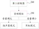
图7所示为本公开根据一示例性实施例示出的无线耳机200的功能器件的控制示意图。在一个实施例中,参考图7,无线耳机200包括设于耳机本体210内的音频模组250和第二控制器260,音频模组250与第二控制器260电连接,第二触电点240与终端设备100电连接时,第二控制器260控制音频模组250的工作模式为扬声器模式。一些实施例中,当无线耳机200与终端设备100电连接时,第二控制器260控制音频模组250将音量调大,以使无线耳机200以扬声器模式工作,进而利于终端设备100播放音频。另一些实施例中,以扬声器模式工作的无线耳机200与终端设备100自带的扬声器结合,可发出立体声效提升用户体验。另一些实施例中,当无线耳机200脱离终端设备100时,第二控制器260控制音频模组250将音量调小,以使无线耳机200以耳机模式工作。通过无线耳机200自动调整工作模式,利于提升用户体验,增加市场竞争力。FIG. 7 is a schematic control diagram of functional devices of the
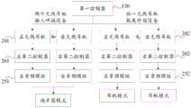
在一个实施例中,继续参考图1,收纳槽111的数目为至少一个,分别收纳至少一个无线耳机200。无线耳机200的数目为至少一个,无线耳机200在脱离收纳槽111之后,与终端设备100无线连接。比如,收纳槽111的数目为两个,无线耳机200包括左无线耳机201和右无线耳机202,分别收纳于两个收纳槽111内。图8所示为本公开根据一示例性实施例示出的与终端设备100不同配合关系时无线耳机200的工作示意图。左无线耳机201包括电连接的左第二控制器261和左音频模组251,右无线耳机202包括电连接的右第二控制器262和右音频模组252。参考图8,当左无线耳机201和右无线耳机202均插入终端设备100的收纳槽111之后,左第二控制器261控制左音频模组251调大音量,使左无线耳机201以扬声器模式工作,右第二控制器262控制右音频模组252调大音量,使右无线耳机202以扬声器模式工作。当左无线耳机201由终端设备100弹出后,左第二控制器261控制左音频模组251调小音量,使左无线耳机201以耳机模式工作,右第二控制器262控制右音频模组252调小音量,使右无线耳机202以耳机模式工作。在一个实施例中,当左无线耳机201和右无线耳机202任一只脱离终端设备100后,两只无线耳机200均以耳机模式工作,这利于用户使用单只无线耳机200。In one embodiment, with continued reference to FIG. 1 , the number of
图9所示为本公开根据一示例性实施例示出的无线耳机200与终端设备100无线连接时的工作示意图。在一个实施例中,参考图9,在左无线耳机201与右无线耳机202脱离收纳槽111之后,均与终端设备100无线连接,且左无线耳机201与右无线耳机202无线连接。一些实施例中,在脱离收纳槽111之后,左无线耳机201与右无线耳机202无线连接,以相互反馈数据,保证左无线耳机201和右无线耳机202工作的同步性。在一个实施例中,左无线耳机201包括与左第二控制器261电连接的左传感器,右无线耳机202包括与右第二控制器262电连接的右传感器。左传感器用于检测左无线耳机201是否处于无线连接状态,若左无线耳机201处于无线连接状态,则向终端设备100的第一控制器130反馈数据。同理,右传感器用于检测右无线耳机202是否处于无线连接状态,若右无线耳机202处于无线连接状态,则向终端设备100的第一控制器130反馈数据。终端设备100基于所反馈的数据,控制左无线耳机201和右无线耳机202工作的同步性。FIG. 9 is a schematic diagram showing the operation of the
图10所示为本公开根据一示例性实施例示出的与终端设备100不同配合关系时无线耳机200的工作示意图。在一个实施例中,无线耳机200还包括设于耳机本体210内的麦克风及电池,均与第二控制器260电连接。当无线耳机200与终端设备100无线连接时,通过麦克风对用户通话声音录音,并转成电信号进行传递。参考图10,当无线耳机200插入终端设备100的收纳槽111之后,第二控制器260控制无线耳机200以扬声器模式工作,控制麦克风关闭。当无线耳机200由终端设备100弹出后,第二控制器260控制无线耳机200以耳机模式工作,并控制麦克风开启,以方便录音。FIG. 10 is a schematic diagram of the operation of the
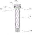
图11所示为本公开根据一示例性实施例示出的无线耳机200在被佩戴时的状态图,图11示出了无线耳机200的正视图和侧视图。图12所示为本公开根据一示例性实施例示出的无线耳机200在被收纳时的状态图。在一个实施例中,耳机本体210与耳机头220可转动连接。一些实施例中,当用户佩戴无线耳机200时,可转动耳机本体210或耳机头220,使无线耳机200为图11中的状态。当用户将无线耳机200收纳于终端设备100时,可转动耳机本体210或耳机头220,使无线耳机200为图12中的状态。在一个实施例中,耳机本体210与耳机头220通过销轴270实现可转动连接。FIG. 11 shows a state diagram of the
对于方法实施例而言,由于其基本对应于装置实施例,所以相关之处参见装置实施例的部分说明即可。方法实施例和装置实施例互为补充。As for the method embodiments, since they basically correspond to the apparatus embodiments, reference may be made to some descriptions of the apparatus embodiments for related parts. The method embodiments and the apparatus embodiments complement each other.
本公开上述各个实施例,在不产生冲突的情况下,可以互为补充。The foregoing embodiments of the present disclosure may complement each other without conflict.
以上所述仅为本公开的较佳实施例而已,并不用以限制本公开,凡在本公开的精神和原则之内,所做的任何修改、等同替换、改进等,均应包含在本公开保护的范围之内。The above descriptions are only preferred embodiments of the present disclosure, and are not intended to limit the present disclosure. Any modifications, equivalent replacements, improvements, etc. made within the spirit and principles of the present disclosure shall be included in the present disclosure. within the scope of protection.
Claims (15)
Translated fromChinesePriority Applications (3)
| Application Number | Priority Date | Filing Date | Title |
|---|---|---|---|
| CN201921568931.6UCN210927937U (en) | 2019-09-19 | 2019-09-19 | Terminal equipment, wireless headsets and electronic equipment components |
| US16/737,565US11109140B2 (en) | 2019-09-19 | 2020-01-08 | Terminal device, wireless headset and electronic device component |
| EP20152449.3AEP3796625B1 (en) | 2019-09-19 | 2020-01-17 | Terminal device, wireless headset and electronic device component |
Applications Claiming Priority (1)
| Application Number | Priority Date | Filing Date | Title |
|---|---|---|---|
| CN201921568931.6UCN210927937U (en) | 2019-09-19 | 2019-09-19 | Terminal equipment, wireless headsets and electronic equipment components |
Publications (1)
| Publication Number | Publication Date |
|---|---|
| CN210927937Utrue CN210927937U (en) | 2020-07-03 |
Family
ID=69177088
Family Applications (1)
| Application Number | Title | Priority Date | Filing Date |
|---|---|---|---|
| CN201921568931.6UActiveCN210927937U (en) | 2019-09-19 | 2019-09-19 | Terminal equipment, wireless headsets and electronic equipment components |
Country Status (3)
| Country | Link |
|---|---|
| US (1) | US11109140B2 (en) |
| EP (1) | EP3796625B1 (en) |
| CN (1) | CN210927937U (en) |
Cited By (3)
| Publication number | Priority date | Publication date | Assignee | Title |
|---|---|---|---|---|
| CN112351130A (en)* | 2020-11-23 | 2021-02-09 | 西安芯海微电子科技有限公司 | Electronic equipment protective housing and electronic equipment |
| CN112804611A (en)* | 2021-01-29 | 2021-05-14 | 北京小米移动软件有限公司 | Storage module and earphone assembly |
| CN118945517A (en)* | 2024-08-12 | 2024-11-12 | 北京暖开科技有限公司 | Intelligent speaker and control method thereof |
Families Citing this family (3)
| Publication number | Priority date | Publication date | Assignee | Title |
|---|---|---|---|---|
| USD951918S1 (en)* | 2019-06-07 | 2022-05-17 | Deok Seon Lee | Wireless earphone |
| USD938942S1 (en)* | 2019-08-07 | 2021-12-21 | Beijing Xiaomi Mobile Software Co., Ltd. | Earphone |
| CN114172988A (en)* | 2021-12-15 | 2022-03-11 | Oppo广东移动通信有限公司 | Electronic device |
Family Cites Families (14)
| Publication number | Priority date | Publication date | Assignee | Title |
|---|---|---|---|---|
| WO2007061213A1 (en)* | 2005-11-28 | 2007-05-31 | Wise&Blue Co., Ltd. | Wireless headset and control method thereof |
| KR101128170B1 (en) | 2006-05-10 | 2012-03-23 | 엘지전자 주식회사 | Portable terminal having acoustic transducer and the control method |
| KR100755823B1 (en) | 2006-07-28 | 2007-09-05 | 주식회사 에스엘오디오랩 | Hand Strap Type Wireless Mono Headset |
| US9565490B2 (en)* | 2011-05-02 | 2017-02-07 | Apple Inc. | Dual mode headphones and methods for constructing the same |
| WO2015026859A1 (en) | 2013-08-19 | 2015-02-26 | Symphonic Audio Technologies Corp. | Audio apparatus and methods |
| DK3151582T3 (en) | 2015-09-30 | 2020-10-12 | Apple Inc | HEADPHONE WITH CHARGING SYSTEM CASE |
| CN108540592A (en) | 2017-03-01 | 2018-09-14 | 深圳市乔威电源有限公司 | A kind of mobile phone carrying bluetooth headset |
| WO2019013352A1 (en)* | 2017-07-13 | 2019-01-17 | 新日鐵住金株式会社 | Oriented electromagnetic steel plate |
| KR101885734B1 (en)* | 2017-11-20 | 2018-09-10 | 주식회사 아론 | A case including a speaker for outputting sound using earphones |
| CN107968866B (en) | 2017-11-22 | 2019-10-29 | 维沃移动通信有限公司 | A kind of terminal device and audio communication method |
| CN207926666U (en)* | 2018-02-09 | 2018-09-28 | 广东欧珀移动通信有限公司 | Mobile terminal |
| EP3668117B1 (en)* | 2018-12-14 | 2023-06-28 | GN Hearing A/S | Earpiece for determining state of closing element for vent |
| US11284181B2 (en)* | 2018-12-20 | 2022-03-22 | Microsoft Technology Licensing, Llc | Audio device charging case with data connectivity |
| US11166093B2 (en)* | 2019-03-19 | 2021-11-02 | Logitech Europe S.A. | Earphone device support and case |
- 2019
- 2019-09-19CNCN201921568931.6Upatent/CN210927937U/enactiveActive
- 2020
- 2020-01-08USUS16/737,565patent/US11109140B2/enactiveActive
- 2020-01-17EPEP20152449.3Apatent/EP3796625B1/enactiveActive
Cited By (4)
| Publication number | Priority date | Publication date | Assignee | Title |
|---|---|---|---|---|
| CN112351130A (en)* | 2020-11-23 | 2021-02-09 | 西安芯海微电子科技有限公司 | Electronic equipment protective housing and electronic equipment |
| CN112804611A (en)* | 2021-01-29 | 2021-05-14 | 北京小米移动软件有限公司 | Storage module and earphone assembly |
| CN118945517A (en)* | 2024-08-12 | 2024-11-12 | 北京暖开科技有限公司 | Intelligent speaker and control method thereof |
| CN118945517B (en)* | 2024-08-12 | 2025-07-29 | 深圳市众智高新电子科技有限公司 | Intelligent sound box and control method thereof |
Also Published As
| Publication number | Publication date |
|---|---|
| EP3796625A1 (en) | 2021-03-24 |
| EP3796625B1 (en) | 2022-03-09 |
| US20210092506A1 (en) | 2021-03-25 |
| US11109140B2 (en) | 2021-08-31 |
Similar Documents
| Publication | Publication Date | Title |
|---|---|---|
| CN210927937U (en) | Terminal equipment, wireless headsets and electronic equipment components | |
| US9826302B2 (en) | Electronic device with magnetically stowable speaker assemblies | |
| US9723394B2 (en) | Headphone clasping device and method | |
| TWI739210B (en) | Earbud case with charging system | |
| CN213638137U (en) | Portable wireless microphone system | |
| EP4140355B1 (en) | Earphone case and wireless earphone | |
| US11638082B2 (en) | Earphone with detachable add-on unit | |
| WO2023246716A1 (en) | Charging box and earbud assembly | |
| CN112511946A (en) | True wireless earphone and charging bin for preventing left earphone and right earphone from being misplaced | |
| CN214101727U (en) | Storage module and headphone assembly | |
| CN213126421U (en) | Wireless earphone assembly and electronic equipment assembly | |
| CN210518763U (en) | In-ear wireless earphone capable of freely adjusting angle | |
| CN112804611A (en) | Storage module and earphone assembly | |
| CN111479187A (en) | Bracelet formula TWS device | |
| CN213305756U (en) | Loudspeaker capable of accommodating and charging microphone | |
| CN219659880U (en) | Earphone | |
| CN218570431U (en) | Novel earphone structure | |
| CN213906896U (en) | Terminal device and Bluetooth headset | |
| CN221575582U (en) | Telescopic earcap and in-ear and open switchable earphone | |
| CN219248032U (en) | Semi-open Bluetooth headset | |
| CN223231292U (en) | An ear-hook Bluetooth headset | |
| CN210157351U (en) | Headphone components and headphone devices | |
| CN114363748A (en) | Wireless headset components and electronic device components | |
| CN120075681A (en) | Headphone components and headphone devices | |
| CN113949960A (en) | Earphone capable of being charged wirelessly |
Legal Events
| Date | Code | Title | Description |
|---|---|---|---|
| GR01 | Patent grant | ||
| GR01 | Patent grant |