CN210905950U - Water-soluble fertilizer mixing stirring device - Google Patents
Water-soluble fertilizer mixing stirring deviceDownload PDFInfo
- Publication number
- CN210905950U CN210905950UCN201921982283.9UCN201921982283UCN210905950UCN 210905950 UCN210905950 UCN 210905950UCN 201921982283 UCN201921982283 UCN 201921982283UCN 210905950 UCN210905950 UCN 210905950U
- Authority
- CN
- China
- Prior art keywords
- shaft
- stirring
- fixedly connected
- gear
- plate
- Prior art date
- Legal status (The legal status is an assumption and is not a legal conclusion. Google has not performed a legal analysis and makes no representation as to the accuracy of the status listed.)
- Expired - Fee Related
Links
Images


Landscapes
- Fertilizers (AREA)
- Accessories For Mixers (AREA)
- Fertilizing (AREA)
Abstract
Description
Translated fromChinese技术领域technical field
本实用新型涉及肥料加工技术领域,具体为一种水溶肥料混合搅拌装置。The utility model relates to the technical field of fertilizer processing, in particular to a mixing and stirring device for water-soluble fertilizers.
背景技术Background technique
水溶性肥料,是一种可以完全溶于水的多元复合肥料,它能迅速地溶解于水中,更容易被作物吸收,而且其吸收利用率相对较高,更为关键的是它可以应用于喷滴灌等设施农业,实现水肥一体化,达到省水省肥省工的效能。但是,现有的水溶肥料混合搅拌装置在搅拌的时候效率太低,造成供应不上上需求,降低了后期的工作效率。Water-soluble fertilizer is a multi-component compound fertilizer that can be completely dissolved in water. It can be quickly dissolved in water and is more easily absorbed by crops, and its absorption and utilization rate is relatively high. More importantly, it can be used in spraying. Facility agriculture such as drip irrigation realizes the integration of water and fertilizer, and achieves the efficiency of saving water, fertilizer and labor. However, the efficiency of the existing water-soluble fertilizer mixing and stirring device is too low during stirring, resulting in insufficient supply to meet demand and reducing work efficiency in the later stage.
实用新型内容Utility model content
本实用新型要解决的技术问题是克服现有的缺陷,提供一种水溶肥料混合搅拌装置,在搅拌时效率高,能够很快的供应需求,可以有效解决背景技术中的问题。The technical problem to be solved by the utility model is to overcome the existing defects and provide a water-soluble fertilizer mixing and stirring device, which has high efficiency during stirring, can quickly supply demand, and can effectively solve the problems in the background technology.
为实现上述目的,本实用新型提供如下技术方案:一种水溶肥料混合搅拌装置,包括底板、支撑板、搅拌轴转动单元、搅拌轴移动单元和搅拌桶;In order to achieve the above purpose, the utility model provides the following technical solutions: a water-soluble fertilizer mixing and stirring device, comprising a bottom plate, a support plate, a stirring shaft rotating unit, a stirring shaft moving unit and a stirring barrel;
底板:所述底板的上表面左端固定连接有支撑柱,所述底板的上表面中部固定连接有搅拌桶,所述支撑柱的上部前侧固定连接有固定柱一,所述固定柱一的前端转动连接有转轴一,所述支撑柱的中部前侧固定连接有固定杆,所述支撑柱的左侧面中部固定连接有固定柱二,所述固定柱二的前端转动连接有转轴二;Bottom plate: a support column is fixedly connected to the left end of the upper surface of the bottom plate, a stirring bucket is fixedly connected to the middle part of the upper surface of the bottom plate, a fixed column one is fixedly connected to the upper front side of the support column, and the front end of the first fixed column is fixedly connected A rotating shaft is rotatably connected, a fixing rod is fixedly connected to the front side of the middle part of the supporting column, a
支撑板:所述支撑板固定连接在支撑柱的上端,所述支撑板的上表面中部固定连接有固定板,所述支撑板的前端左侧活动套接有管轴,所述管轴的上端固定连接有限位环,所述限位环与支撑板转动连接,所述管轴的内部活动套接有搅拌轴,所述搅拌轴的中部固定套接有齿环,所述搅拌轴的下端固定连接有搅拌杆,所述搅拌杆的下表面固定连接有搅拌棒,所述支撑板的前端右侧活动套接有中心轴,所述中心轴的下端与固定杆转动连接;Support plate: the support plate is fixedly connected to the upper end of the support column, the middle part of the upper surface of the support plate is fixedly connected with a fixed plate, the front left side of the front end of the support plate is movably sleeved with a tube shaft, and the upper end of the tube shaft A limit ring is fixedly connected, the limit ring is rotatably connected with the support plate, a stirring shaft is movably sleeved inside the pipe shaft, a gear ring is fixedly sleeved in the middle of the stirring shaft, and the lower end of the stirring shaft is fixed A stirring rod is connected, the lower surface of the stirring rod is fixedly connected with a stirring rod, a center shaft is movably sleeved on the right side of the front end of the support plate, and the lower end of the center shaft is rotatably connected with the fixed rod;
搅拌轴转动单元:所述搅拌轴转动单元安装在支撑板上;Stirring shaft rotating unit: the stirring shaft rotating unit is installed on the support plate;
搅拌轴移动单元:所述搅拌轴移动单元安装在固定柱一上;Stirring shaft moving unit: the stirring shaft moving unit is installed on the
其中:还包括控制开关,所述控制开关安装在底板的上表面左侧,所述控制开关的输入端电连接外部电源的输出端。Wherein: it also includes a control switch, the control switch is installed on the left side of the upper surface of the base plate, and the input end of the control switch is electrically connected to the output end of the external power supply.
进一步的,所述搅拌轴转动单元包含电机、传动齿轮、从动齿轮、齿盘一和齿盘二,所述电机安装在固定板上,所述传动齿轮固定套接在电机的输出轴上,所述从动齿轮固定套接在中心轴的上端,所述齿盘一固定套接在管轴的下端,所述齿盘二固定套接在中心轴的中部,所述传动齿轮和从动齿轮啮合,所述齿盘一和齿盘二啮合,所述电机的输入端电连接控制开关的输出端。通过启动电机,电机的输出轴转动带动传动齿轮转动,传动齿轮转动带动从动齿轮转动,从动齿轮转动带动中心轴转动,中心轴转动带动齿盘二转动,齿盘二转动带动齿盘一转动,齿盘一转动带动管轴转动,管轴转动带动搅拌轴转动。Further, the stirring shaft rotating unit includes a motor, a transmission gear, a driven gear, a first gear plate and a second gear plate, the motor is mounted on the fixed plate, and the transmission gear is fixedly sleeved on the output shaft of the motor, The driven gear is fixedly sleeved on the upper end of the central shaft, the first toothed plate is fixedly sleeved on the lower end of the pipe shaft, the second toothed plate is fixedly sleeved on the middle of the central shaft, the transmission gear and the driven gear Meshing, the first gear plate and the second gear plate are engaged, and the input end of the motor is electrically connected to the output end of the control switch. By starting the motor, the rotation of the output shaft of the motor drives the rotation of the transmission gear, the rotation of the transmission gear drives the rotation of the driven gear, the rotation of the driven gear drives the rotation of the central shaft, the rotation of the central shaft drives the rotation of the second gear plate, and the rotation of the second gear plate drives the first gear plate to rotate , the rotation of the toothed plate drives the rotation of the pipe shaft, and the rotation of the pipe shaft drives the rotation of the stirring shaft.
进一步的,所述搅拌轴移动单元包含蜗轮、曲柄一、蜗杆、连杆、齿轮、曲柄二,所述蜗轮固定套接在转轴一的中部,所述曲柄一的一端固定套接在转轴一的前端,所述曲柄一的另一端通过销轴活动连接在连杆的一端,所述连杆的另一端通过销轴活动连接在曲柄二的一端,所述曲柄二的另一端固定套接在转轴二的前端,所述蜗杆固定套接在中心轴的下端,所述齿轮固定套接在转轴二的中部,所述蜗轮和蜗杆啮合,所述齿轮和齿环配合。中心轴转动带动蜗杆转动,蜗杆转动带动蜗轮转动,蜗轮转动带动曲炳一转动,曲柄一转动带动连杆摆动,连杆摆动带动曲柄二摆动,曲柄二摆动带动齿轮转动,齿轮转动带动齿环移动,齿环移动带动搅拌轴移动。Further, the stirring shaft moving unit includes a worm wheel, a crank, a worm, a connecting rod, a gear, and a second crank. At the front end, the other end of the first crank is movably connected to one end of the connecting rod through a pin, the other end of the connecting rod is movably connected to one end of the second crank through the pin, and the other end of the second crank is fixedly sleeved on the rotating shaft At the front end of the second shaft, the worm is fixedly sleeved on the lower end of the central shaft, the gear is fixedly sleeved on the middle of the second rotating shaft, the worm gear is meshed with the worm, and the gear is matched with the gear ring. The rotation of the central shaft drives the rotation of the worm, the rotation of the worm drives the rotation of the worm wheel, the rotation of the worm wheel drives the rotation of the crank, the rotation of the crank drives the swing of the connecting rod, the swing of the connecting rod drives the swing of the second crank, the swing of the second crank drives the rotation of the gear, and the rotation of the gear drives the movement of the ring gear , the movement of the ring gear drives the movement of the stirring shaft.
进一步的,还包括出口和阀门,所述出口开设在搅拌桶的下端,所述阀门设置在出口的外侧面上。通过出口和阀门,可以方便且快捷的放出搅拌后的混合肥料。Further, it also includes an outlet and a valve, the outlet is opened at the lower end of the mixing barrel, and the valve is arranged on the outer side of the outlet. Through the outlet and valve, the mixed fertilizer after stirring can be released conveniently and quickly.
进一步的,还包括薄片和十字片,所述薄片固定连接在搅拌杆的外端,所述十字片固定连接在搅拌棒的下端。通过薄片和十字片,可以进一步增加搅拌的效果。Further, it also includes a thin piece and a cross piece, the thin piece is fixedly connected to the outer end of the stirring rod, and the cross piece is fixedly connected to the lower end of the stirring rod. With thin slices and cross slices, the stirring effect can be further increased.
与现有技术相比,本实用新型的有益效果是:本水溶肥料混合搅拌装置,具有以下好处:Compared with the prior art, the beneficial effects of the present utility model are: the water-soluble fertilizer mixing and stirring device has the following advantages:
1、本水溶肥料混合搅拌装置设置了搅拌轴转动单元,电机输出轴转动带动传动齿轮转动,传动齿轮转动带动从动齿轮转动,从动齿轮转动带动中心轴转动,中心轴转动带动齿盘二转动,齿盘二转动带动齿盘一转动,齿盘一转动带动管轴转动,管轴转动带动搅拌轴转动;1. This water-soluble fertilizer mixing and stirring device is equipped with a stirring shaft rotation unit. The rotation of the motor output shaft drives the rotation of the transmission gear, the rotation of the transmission gear drives the rotation of the driven gear, the rotation of the driven gear drives the rotation of the central shaft, and the rotation of the central shaft drives the rotation of the second gear plate. , the second rotation of the toothed plate drives the first rotation of the toothed plate, the first rotation of the toothed plate drives the rotation of the pipe shaft, and the rotation of the pipe shaft drives the rotation of the stirring shaft;
2、本水溶肥料混合搅拌装置设置了搅拌轴移动单元,中心轴转动带动蜗杆转动,蜗杆转动带动蜗轮转动,蜗轮转动带动曲炳一转动,曲柄一转动带动连杆摆动,连杆摆动带动曲柄二摆动,曲柄二摆动带动齿轮转动,齿轮转动带动齿环移动,齿环移动带动搅拌轴上下移动;2. This water-soluble fertilizer mixing and stirring device is equipped with a stirring shaft moving unit. The rotation of the central shaft drives the worm to rotate, the rotation of the worm drives the rotation of the worm wheel, the rotation of the worm wheel drives the rotation of Qu Bing, the rotation of the crank drives the swing of the connecting rod, and the swing of the connecting rod drives the second crank Swing, the second swing of the crank drives the gear to rotate, the gear rotation drives the gear ring to move, and the gear ring moves to drive the stirring shaft to move up and down;
3、该水溶肥料混合搅拌装置在搅拌或者肥料的时候,加快了搅拌的效率,从而能够供应上需求,能够提高生产的效率。3. The water-soluble fertilizer mixing and stirring device speeds up the stirring efficiency when stirring or fertilizer, so that the demand can be supplied and the production efficiency can be improved.
附图说明Description of drawings
图1为本实用新型结构示意图Fig. 1 is the structural representation of the utility model
图2为本实用新型搅拌轴移动单元结构示意图Fig. 2 is the structural schematic diagram of the stirring shaft moving unit of the utility model
图3为本实用新型支撑柱结构示意图Figure 3 is a schematic diagram of the structure of the support column of the present invention
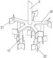
图4为本实用新型搅拌杆结构示意图。Figure 4 is a schematic diagram of the structure of the stirring rod of the present invention.
图中:1底板、2支撑柱、3支撑板、4中心轴、5搅拌轴、6搅拌轴转动单元、61电机、62传动齿轮、63从动齿轮、64齿盘一、65齿盘二、7固定柱一、8搅拌轴移动单元、81蜗轮、82曲柄一、83蜗杆、84连杆、85齿轮、86曲柄二、9齿环、10固定杆、11固定柱二、12管轴、13固定板、14转轴一、15转轴二、16搅拌杆、17搅拌棒、18搅拌桶、19出口、20阀门、21薄片、22十字片、23限位环、24控制开关。In the figure: 1 bottom plate, 2 support column, 3 support plate, 4 central shaft, 5 stirring shaft, 6 stirring shaft rotating unit, 61 motor, 62 transmission gear, 63 driven gear, 64 gear plate one, 65 gear plate two, 7 fixed column one, 8 stirring shaft moving unit, 81 worm gear, 82 crank one, 83 worm, 84 connecting rod, 85 gear, 86 crank two, 9 gear ring, 10 fixed rod, 11 fixed column two, 12 pipe shaft, 13 Fixed plate, 14 rotating shaft one, 15 rotating shaft two, 16 stirring rod, 17 stirring rod, 18 stirring barrel, 19 outlet, 20 valve, 21 sheet, 22 cross piece, 23 limit ring, 24 control switch.
具体实施方式Detailed ways
下面将结合本实用新型实施例中的附图,对本实用新型实施例中的技术方案进行清楚、完整地描述,显然,所描述的实施例仅仅是本实用新型一部分实施例,而不是全部的实施例。基于本实用新型中的实施例,本领域普通技术人员在没有做出创造性劳动前提下所获得的所有其他实施例,都属于本实用新型保护的范围。The technical solutions in the embodiments of the present utility model will be clearly and completely described below with reference to the accompanying drawings in the embodiments of the present utility model. Obviously, the described embodiments are only a part of the embodiments of the present utility model, rather than all the implementations. example. Based on the embodiments of the present invention, all other embodiments obtained by those of ordinary skill in the art without creative work fall within the protection scope of the present invention.
请参阅图1-4,本实用新型提供一种技术方案:一种水溶肥料混合搅拌装置,包括底板1、支撑板3、搅拌轴转动单元6、搅拌轴移动单元8和搅拌桶18;1-4, the present utility model provides a technical solution: a water-soluble fertilizer mixing and stirring device, comprising a
底板1:底板1的上表面左端固定连接有支撑柱2,底板1的上表面中部固定连接有搅拌桶18,支撑柱2的上部前侧固定连接有固定柱一7,固定柱一7的前端转动连接有转轴一14,支撑柱2的中部前侧固定连接有固定杆10,支撑柱2的左侧面中部固定连接有固定柱二11,固定柱二11的前端转动连接有转轴二15;还包括出口19和阀门20,出口19开设在搅拌桶18的下端,阀门20设置在出口的外侧面上。通过出口19和阀门20,可以方便且快捷的放出搅拌后的混合肥料;Bottom plate 1: The left end of the upper surface of the
支撑板3:支撑板3固定连接在支撑柱2的上端,支撑板3的上表面中部固定连接有固定板13,支撑板3的前端左侧活动套接有管轴12,管轴12的上端固定连接有限位环23,限位环23与支撑板3转动连接,管轴12的内部活动套接有搅拌轴5,搅拌轴5的中部固定套接有齿环9,搅拌轴5的下端固定连接有搅拌杆16,搅拌杆16的下表面固定连接有搅拌棒17,支撑板3的前端右侧活动套接有中心轴4,中心轴4的下端与固定杆10转动连接;还包括薄片21和十字片22,薄片21固定连接在搅拌杆16的外端,十字片22固定连接在搅拌棒17的下端。通过薄片21和十字片22,可以进一步增加搅拌的效果;Support plate 3: The
搅拌轴转动单元6:搅拌轴转动单元6安装在支撑板3上;搅拌轴转动单元6包含电机61、传动齿轮62、从动齿轮63、齿盘一64和齿盘二65,电机61安装在固定板13上,传动齿轮62固定套接在电机61的输出轴上,从动齿轮63固定套接在中心轴4的上端,齿盘一64固定套接在管轴12的下端,齿盘二65固定套接在中心轴4的中部,传动齿轮62和从动齿轮63啮合,齿盘一64和齿盘二65啮合,电机61的输入端电连接控制开关24的输出端。通过启动电机61,电机61的输出轴转动带动传动齿轮62转动,传动齿轮62转动带动从动齿轮63转动,从动齿轮63转动带动中心轴4转动,中心轴4转动带动齿盘二65转动,齿盘二65转动带动齿盘一64转动,齿盘一64转动带动管轴12转动,管轴12转动带动搅拌轴5转动;Stirring shaft rotating unit 6: The stirring
搅拌轴移动单元8:搅拌轴移动单元8安装在固定柱一7上;搅拌轴移动单元8包含蜗轮81、曲柄一82、蜗杆83、连杆84、齿轮85、曲柄二86,蜗轮81固定套接在转轴一14的中部,曲柄一82的一端固定套接在转轴一14的前端,曲柄一82的另一端通过销轴活动连接在连杆84的一端,连杆84的另一端通过销轴活动连接在曲柄二86的一端,曲柄二86的另一端固定套接在转轴二14的前端,蜗杆83固定套接在中心轴4的下端,齿轮85固定套接在转轴二15的中部,蜗轮81和蜗杆83啮合,齿轮85和齿环9配合。中心轴4转动带动蜗杆83转动,蜗杆83转动带动蜗轮81转动,蜗轮81转动带动曲炳一82转动,曲柄一82转动带动连杆84摆动,连杆84摆动带动曲柄二86摆动,曲柄二86摆动带动齿轮85转动,齿轮85转动带动齿环9移动,齿环9移动带动搅拌轴5移动;Stirring shaft moving unit 8: stirring
其中:还包括控制开关24,控制开关24安装在底板1的上表面左侧,控制开关24的输入端电连接外部电源的输出端。Wherein: it also includes a
在使用时:When using:
首先,将搅拌桶18内倒入需要搅拌的肥料,按下控制开关24上控制电机61的控制按钮,然后电机61启动,电机61的输出轴转动带动传动齿轮62转动,传动齿轮62转动带动从动齿轮63转动,从动齿轮63转动带动中心轴4转动,中心轴4转动带动齿盘二65转动,齿盘二65转动带动齿盘一64转动,齿盘一64转动带动管轴12转动,管轴12转动带动搅拌轴5转动,中心轴4转动带动蜗杆83转动,蜗杆83转动带动蜗轮81转动,蜗轮81转动带动曲炳一82转动,曲柄一82转动带动连杆84摆动,连杆84摆动带动曲柄二86摆动,曲柄二86摆动带动齿轮85转动,齿轮85转动带动齿环9移动,齿环9移动带动搅拌轴5移动,然后开始搅拌肥料,薄片21和十字片22可以增加搅拌轴5的搅拌效果,搅拌完成后,通过转动阀门20,然后可以从出口19将搅拌好的肥料放出。First, pour the fertilizer to be stirred into the
值得注意的是,控制开关24上设有与电机61对应的控制按钮,电机61可选用常州云禾机电设备有限公司出品的铝壳电机。控制开关24控制电机61工作采用现有技术中常用的方法。It is worth noting that the
尽管已经示出和描述了本实用新型的实施例,对于本领域的普通技术人员而言,可以理解在不脱离本实用新型的原理和精神的情况下可以对这些实施例进行多种变化、修改、替换和变型,本实用新型的范围由所附权利要求及其等同物限定。Although the embodiments of the present invention have been shown and described, it will be understood by those skilled in the art that various changes and modifications can be made to these embodiments without departing from the principles and spirit of the present invention , alternatives and modifications, the scope of the present invention is defined by the appended claims and their equivalents.
Claims (5)
Priority Applications (1)
| Application Number | Priority Date | Filing Date | Title |
|---|---|---|---|
| CN201921982283.9UCN210905950U (en) | 2019-11-18 | 2019-11-18 | Water-soluble fertilizer mixing stirring device |
Applications Claiming Priority (1)
| Application Number | Priority Date | Filing Date | Title |
|---|---|---|---|
| CN201921982283.9UCN210905950U (en) | 2019-11-18 | 2019-11-18 | Water-soluble fertilizer mixing stirring device |
Publications (1)
| Publication Number | Publication Date |
|---|---|
| CN210905950Utrue CN210905950U (en) | 2020-07-03 |
Family
ID=71355201
Family Applications (1)
| Application Number | Title | Priority Date | Filing Date |
|---|---|---|---|
| CN201921982283.9UExpired - Fee RelatedCN210905950U (en) | 2019-11-18 | 2019-11-18 | Water-soluble fertilizer mixing stirring device |
Country Status (1)
| Country | Link |
|---|---|
| CN (1) | CN210905950U (en) |
Cited By (4)
| Publication number | Priority date | Publication date | Assignee | Title |
|---|---|---|---|---|
| CN112169739A (en)* | 2020-10-19 | 2021-01-05 | 江西金凯化工有限公司 | High-safety chemical stirring reaction kettle |
| CN113019195A (en)* | 2021-03-05 | 2021-06-25 | 李和成 | Medical treatment department of stomatology uses dental cast raw material mixing device |
| CN114570254A (en)* | 2022-02-24 | 2022-06-03 | 江苏滋百农生态农业股份有限公司 | Automatic processing device for functional microbial organic fertilizer |
| CN114602363A (en)* | 2022-03-17 | 2022-06-10 | 郑州铁路职业技术学院 | A kind of building material mixing equipment |
- 2019
- 2019-11-18CNCN201921982283.9Upatent/CN210905950U/ennot_activeExpired - Fee Related
Cited By (4)
| Publication number | Priority date | Publication date | Assignee | Title |
|---|---|---|---|---|
| CN112169739A (en)* | 2020-10-19 | 2021-01-05 | 江西金凯化工有限公司 | High-safety chemical stirring reaction kettle |
| CN113019195A (en)* | 2021-03-05 | 2021-06-25 | 李和成 | Medical treatment department of stomatology uses dental cast raw material mixing device |
| CN114570254A (en)* | 2022-02-24 | 2022-06-03 | 江苏滋百农生态农业股份有限公司 | Automatic processing device for functional microbial organic fertilizer |
| CN114602363A (en)* | 2022-03-17 | 2022-06-10 | 郑州铁路职业技术学院 | A kind of building material mixing equipment |
Similar Documents
| Publication | Publication Date | Title |
|---|---|---|
| CN210905950U (en) | Water-soluble fertilizer mixing stirring device | |
| CN206748736U (en) | Concrete mixing device | |
| CN217722294U (en) | Convenient liquid manure integration irrigation machine | |
| CN204583055U (en) | Batch mixer | |
| CN211562734U (en) | Mixing arrangement for building waste production building block | |
| CN210964933U (en) | All-component mixing device for preparation of diaper | |
| CN210786268U (en) | A device for concentrating pharmaceutical extract | |
| CN219428612U (en) | Fertilizer storage device with stirring function | |
| CN211931363U (en) | Simple and easy device of liquid manure integration | |
| CN211164976U (en) | Low-pressure filling mixing foaming machine | |
| CN211517965U (en) | Based on mulling mortar production is with compounding device | |
| CN209519670U (en) | 84 disinfection alloy melt stirring devices | |
| CN111588058A (en) | Mixed sprinkler of oil of raisin production | |
| CN217967624U (en) | A stirring device for construction engineering with high mixing efficiency | |
| CN220763072U (en) | Stirring transmission structure | |
| CN221948754U (en) | Simple orchard fertilizer and water integrated device | |
| CN221641337U (en) | Concrete mixer convenient to unloading | |
| CN220589757U (en) | Odor-free paint mixing device | |
| CN217016207U (en) | Sauce production is with allotment jar | |
| CN221906606U (en) | Mixer is used in organic fertilizer production | |
| CN219583198U (en) | Ash spraying machine for building decoration | |
| CN220733868U (en) | Irrigation device is maintained to industry heritage landscape | |
| CN219536843U (en) | Photovoltaic power generation water and fertilizer integrated irrigation device | |
| CN223299867U (en) | Guide cylinder mixing device | |
| CN221561777U (en) | Light gypsum mortar preparation facilities |
Legal Events
| Date | Code | Title | Description |
|---|---|---|---|
| GR01 | Patent grant | ||
| GR01 | Patent grant | ||
| CF01 | Termination of patent right due to non-payment of annual fee | Granted publication date:20200703 | |
| CF01 | Termination of patent right due to non-payment of annual fee |