CN210895242U - A computer host box with a vacuuming function - Google Patents
A computer host box with a vacuuming functionDownload PDFInfo
- Publication number
- CN210895242U CN210895242UCN201922288521.2UCN201922288521UCN210895242UCN 210895242 UCN210895242 UCN 210895242UCN 201922288521 UCN201922288521 UCN 201922288521UCN 210895242 UCN210895242 UCN 210895242U
- Authority
- CN
- China
- Prior art keywords
- plate
- fixedly connected
- horizontal plate
- drive motor
- box
- Prior art date
- Legal status (The legal status is an assumption and is not a legal conclusion. Google has not performed a legal analysis and makes no representation as to the accuracy of the status listed.)
- Expired - Fee Related
Links
- 239000000428dustSubstances0.000claimsabstractdescription28
- 238000007789sealingMethods0.000claimsabstractdescription9
- 238000003466weldingMethods0.000claimsdescription3
- 230000017525heat dissipationEffects0.000description2
- 230000007774longtermEffects0.000description2
- 238000012986modificationMethods0.000description2
- 230000004048modificationEffects0.000description2
- 230000009286beneficial effectEffects0.000description1
- 238000004140cleaningMethods0.000description1
- 238000010586diagramMethods0.000description1
- 230000003670easy-to-cleanEffects0.000description1
- 230000000694effectsEffects0.000description1
- 238000009434installationMethods0.000description1
- 238000000034methodMethods0.000description1
Images
Landscapes
- Filtering Of Dispersed Particles In Gases (AREA)
Abstract
Translated fromChinese
Description
Translated fromChinese技术领域technical field
本实用新型涉及继电器技术领域,具体领域为一种带有吸尘功能的电脑主机箱体。The utility model relates to the technical field of relays, in particular to a computer mainframe box with a dust-sucking function.
背景技术Background technique
电脑主机箱体在长时间的使用中,箱体内会落入大量的灰尘,灰尘多可以引发电脑死机、自动关机、自动重启等故障的发生,现有的电脑主机箱体大多只是对主机箱体外的灰尘进行遮挡,对落入主机箱体内的灰尘并不能及时清理,从而导致电脑使用寿命减少。In the long-term use of the computer mainframe box, a large amount of dust will fall into the box. Too much dust can cause the computer to crash, automatically shut down, and automatically restart. The outside dust is blocked, and the dust falling into the host box cannot be cleaned up in time, which will reduce the service life of the computer.
实用新型内容Utility model content
本实用新型的目的在于提供一种带有吸尘功能的电脑主机箱体,以解决现有技术中电脑主机箱体落灰不易清理的问题。The purpose of the utility model is to provide a computer mainframe case with a dust-absorbing function, so as to solve the problem that the dustfall of the computer mainframe case in the prior art is not easy to clean.
为实现上述目的,本实用新型提供如下技术方案:一种带有吸尘功能的电脑主机箱体,包括主机箱体,所述主机箱体内底面一侧固定连接有L形板,所述L形板的横板与主机箱体侧壁固定连接,所述L形板的两侧分别与主机箱体两侧壁固定连接,所述L形板的竖板一侧固定连接有横板,所述横板其余三侧分别与主机箱体的三个侧壁固定连接,所述主机箱体一侧设有除尘口,所述除尘口的一侧铰接有密封盖,所述密封盖上设有出风口,所述出风口内固定安装有过滤网,所述横板顶端固定安装有驱动电机,所述驱动电机输出端穿过横板的底端,所述驱动电机输出轴底端设有通孔,所述横板底端设有刷子,所述刷子的旋转轴顶端固定连接有套筒,所述套筒与驱动电机的输出轴套接,所述套筒上螺接有螺栓,所述螺栓与通孔轴心相对设置,所述螺栓的一端伸入通孔并穿出套筒外,所述螺栓一端螺接有螺母,所述L形板的竖板一侧固定连接有安装板,所述安装板一侧与主机箱体侧壁贴合,所述安装板设置在横板的正上方,所述安装板的底端固定安装有蓄电池组,所述主机箱体一侧的侧壁固定安装有驱动电机开关,所述驱动电机开关设置在安装板与横板之间,所述驱动电机开关通过导线与驱动电机连接,所述驱动电机通过导线与蓄电池组固定连接,所述安装板底端固定安装有吸风机,所述吸风机的输入端穿过L形板的横板并入主机箱体内,所述吸风机的输出端固定连接有软管,所述软管一端穿过安装板和横板并伸入横板、L形板的竖板和主机箱体侧壁形成的空腔内,所述吸风机一侧设有电源插口,所述电源插口内插入导线与电脑主机的USB接口连接。In order to achieve the above purpose, the present utility model provides the following technical solutions: a computer mainframe case with a dust-absorbing function, including a mainframe case, an L-shaped plate is fixedly connected to one side of the bottom surface of the mainframe case, and the L-shaped The horizontal plate of the plate is fixedly connected to the side wall of the mainframe box, the two sides of the L-shaped plate are respectively fixedly connected to the two side walls of the mainframe box, and the horizontal plate is fixedly connected to one side of the vertical plate of the L-shaped plate. The remaining three sides of the horizontal plate are respectively fixedly connected with the three side walls of the main machine box. One side of the main machine box is provided with a dust removal port, and one side of the dust removal port is hinged with a sealing cover, and the sealing cover is provided with an outlet. An air outlet, a filter screen is fixedly installed in the air outlet, a driving motor is fixedly installed at the top of the horizontal plate, the output end of the driving motor passes through the bottom end of the horizontal plate, and the bottom end of the output shaft of the driving motor is provided with a through hole , the bottom end of the horizontal plate is provided with a brush, the top of the rotating shaft of the brush is fixedly connected with a sleeve, the sleeve is sleeved with the output shaft of the drive motor, the sleeve is screwed with bolts, and the bolts It is arranged opposite to the axis of the through hole, one end of the bolt extends into the through hole and goes out of the sleeve, one end of the bolt is screwed with a nut, and one side of the vertical plate of the L-shaped plate is fixedly connected with a mounting plate, so One side of the mounting plate is attached to the side wall of the host box, the mounting plate is arranged just above the horizontal plate, the bottom end of the mounting plate is fixedly installed with a battery pack, and the side wall of the host box is fixed A drive motor switch is installed, the drive motor switch is arranged between the mounting plate and the horizontal plate, the drive motor switch is connected to the drive motor through wires, the drive motor is fixedly connected to the battery pack through wires, and the bottom of the installation plate is A suction fan is fixedly installed at the end, and the input end of the suction fan passes through the horizontal plate of the L-shaped plate and merges into the main box body. The output end of the suction fan is fixedly connected with a hose, and one end of the hose passes through the mounting plate. and the horizontal plate and extend into the cavity formed by the vertical plate of the horizontal plate, the L-shaped plate and the side wall of the host box. interface connection.
优选的,所述主机箱体与L形板通过焊接固定连接。Preferably, the main box and the L-shaped plate are fixedly connected by welding.
与现有技术相比,本实用新型的有益效果是:本装置通吸风机将落入电脑主机箱内的多数灰尘吸入主机箱体侧壁、L形板竖板和横板形成的空腔内,这样便有效的减少了灰尘对电脑的锁坏,而且吸风机在吸出吹尘的同时,可以将风扇排出的热风吸出,加强了电脑主机的散热作用,大大延长了电脑的使用寿命。Compared with the prior art, the beneficial effect of the present utility model is: the suction fan of the device sucks most of the dust falling into the main computer box into the cavity formed by the side wall of the main box, the L-shaped vertical plate and the horizontal plate. In this way, it can effectively reduce the lock damage to the computer by dust, and the suction fan can suck out the hot air discharged by the fan while sucking out the dust, which strengthens the heat dissipation effect of the computer host and greatly prolongs the service life of the computer.
附图说明Description of drawings
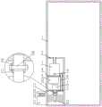
图1为本实用新型的结构示意图。Figure 1 is a schematic structural diagram of the utility model.
图中:1.主机箱体、2.L形板、3.吸风机、4.安装板、5.横板、6.蓄电池组、7.驱动电机、8.软管、9.电源插口、10.螺栓、11.套筒、12.刷子、13.密封盖、14.过滤网、15.出风口、16.驱动电机开关、17.除尘口、18.通孔。In the picture: 1. Main unit box, 2. L-shaped plate, 3. Suction fan, 4. Mounting plate, 5. Horizontal plate, 6. Battery pack, 7. Drive motor, 8. Hose, 9. Power socket, 10. Bolt, 11. Sleeve, 12. Brush, 13. Sealing cover, 14. Filter screen, 15. Air outlet, 16. Drive motor switch, 17. Dust removal port, 18. Through hole.
具体实施方式Detailed ways
下面将结合本实用新型实施例中的附图,对本实用新型实施例中的技术方案进行清楚、完整地描述,显然,所描述的实施例仅仅是本实用新型一部分实施例,而不是全部的实施例。基于本实用新型中的实施例,本领域普通技术人员在没有做出创造性劳动前提下所获得的所有其他实施例,都属于本实用新型保护的范围。The technical solutions in the embodiments of the present utility model will be clearly and completely described below with reference to the accompanying drawings in the embodiments of the present utility model. Obviously, the described embodiments are only a part of the embodiments of the present utility model, rather than all the implementations. example. Based on the embodiments of the present invention, all other embodiments obtained by those of ordinary skill in the art without creative work fall within the protection scope of the present invention.
请参阅图1,本实用新型提供一种技术方案:一种带有吸尘功能的电脑主机箱体,包括主机箱体1,主机箱体1内底面一侧固定连接有L形板2,L形板2的横板与主机箱体1侧壁固定连接,L形板2的两侧分别与主机箱体1两侧壁固定连接,L形板2的竖板一侧固定连接有横板5,横板5其余三侧分别与主机箱体1的三个侧壁固定连接,主机箱体1一侧设有除尘口17,除尘口17的一侧铰接有密封盖13,密封盖13上设有出风口15,出风口15内固定安装有过滤网14,横板5顶端固定安装有驱动电机7,驱动电机7输出端穿过横板5的底端,驱动电机7输出轴底端设有通孔18,横板5底端设有刷子12,刷子12的旋转轴顶端固定连接有套筒11,套筒11与驱动电机7的输出轴套接,套筒11上螺接有螺栓10,螺栓10与通孔18轴心相对设置,螺栓10的一端伸入通孔18并穿出套筒11外,螺栓10一端螺接有螺母,L形板2的竖板一侧固定连接有安装板4,安装板4一侧与主机箱体1侧壁贴合,安装板4设置在横板5的正上方,安装板4的底端固定安装有蓄电池组6,主机箱体1一侧的侧壁固定安装有驱动电机开关16,驱动电机开关16设置在安装板4与横板5之间,驱动电机开关16通过导线与驱动电机7连接,驱动电机7通过导线与蓄电池组6固定连接,安装板4底端固定安装有吸风机3,吸风机3的输入端穿过L形板2的横板并入主机箱体1内,吸风机3的输出端固定连接有软管8,软管8一端穿过安装板4和横板5并伸入横板5、L形板2的竖板和主机箱体1侧壁形成的空腔内,吸风机3一侧设有电源插口9,电源插口9内插入导线与电脑主机的USB接口连接。Please refer to FIG. 1 , the present invention provides a technical solution: a computer mainframe case with a dust-absorbing function, including a
优选的,主机箱体1与L形板2通过焊接固定连接。Preferably, the
工作原理:首先将本装置放置在工作区域,当电脑主机接通电源时,电脑电脑主机的USB接口通电,此时吸风机3开始运行,将主机箱体1内落入的灰尘从输入端吸入,吸风机3的输出端通过软管8将灰尘排出进入主机箱体1侧壁、L形板2、和横板5形成的空腔内,同时由于电脑的长时间使用,吸风机3可以将电脑主机风扇排出的部分热风吸走,起到散热的作用,当气流进入主机箱体1侧壁、L形板2、和横板5形成的空腔内,气流从出风口15处排出,出风口15内固定安装有过滤网14,过滤网14将气流内的多数灰尘过滤下。Working principle: first place the device in the working area, when the computer host is powered on, the USB interface of the computer host is powered on, and the suction fan 3 starts to run, sucking the dust falling into the
过滤下的灰尘长时间在主机箱体1侧壁、L形板2、和横板5形成的空腔内堆积,需要进行清理,此时按下驱动电机开关16,驱动电机7的输出端带动刷子12进行旋转,将主机箱体1侧壁、L形板2、和横板5形成的空腔内的灰尘扫落后,再次按下驱动电机开关16使驱动电机7停止,打开密封盖13将扫落在主机箱体1侧壁、L形板2、和横板5形成的空腔内的灰尘清理而出,旋转螺栓10的螺母使其与螺栓10脱离,旋转螺栓10使其与通孔18脱离,将刷子12取下,人工将刷子12拿到室外,将残留在刷子12上的灰尘抖落,相反操作以上步骤将以本装置复位,这样便完成了对堆积灰尘的清理,操作起来简单快捷,又保护了电脑主机箱体不会被落入的灰尘损坏。The filtered dust accumulates in the cavity formed by the side wall of the
尽管已经示出和描述了本实用新型的实施例,对于本领域的普通技术人员而言,可以理解在不脱离本实用新型的原理和精神的情况下可以对这些实施例进行多种变化、修改、替换和变型,本实用新型的范围由所附权利要求及其等同物限定。Although the embodiments of the present invention have been shown and described, it will be understood by those skilled in the art that various changes and modifications can be made to these embodiments without departing from the principles and spirit of the present invention , alternatives and modifications, the scope of the present invention is defined by the appended claims and their equivalents.
Claims (2)
Translated fromChinesePriority Applications (1)
| Application Number | Priority Date | Filing Date | Title |
|---|---|---|---|
| CN201922288521.2UCN210895242U (en) | 2019-12-19 | 2019-12-19 | A computer host box with a vacuuming function |
Applications Claiming Priority (1)
| Application Number | Priority Date | Filing Date | Title |
|---|---|---|---|
| CN201922288521.2UCN210895242U (en) | 2019-12-19 | 2019-12-19 | A computer host box with a vacuuming function |
Publications (1)
| Publication Number | Publication Date |
|---|---|
| CN210895242Utrue CN210895242U (en) | 2020-06-30 |
Family
ID=71319348
Family Applications (1)
| Application Number | Title | Priority Date | Filing Date |
|---|---|---|---|
| CN201922288521.2UExpired - Fee RelatedCN210895242U (en) | 2019-12-19 | 2019-12-19 | A computer host box with a vacuuming function |
Country Status (1)
| Country | Link |
|---|---|
| CN (1) | CN210895242U (en) |
Cited By (2)
| Publication number | Priority date | Publication date | Assignee | Title |
|---|---|---|---|---|
| CN112114646A (en)* | 2020-09-23 | 2020-12-22 | 广州联合医生集团有限公司 | JSP-based information exchange terminal |
| CN112462888A (en)* | 2020-12-18 | 2021-03-09 | 刘萍 | Computer cabinet |
- 2019
- 2019-12-19CNCN201922288521.2Upatent/CN210895242U/ennot_activeExpired - Fee Related
Cited By (2)
| Publication number | Priority date | Publication date | Assignee | Title |
|---|---|---|---|---|
| CN112114646A (en)* | 2020-09-23 | 2020-12-22 | 广州联合医生集团有限公司 | JSP-based information exchange terminal |
| CN112462888A (en)* | 2020-12-18 | 2021-03-09 | 刘萍 | Computer cabinet |
Similar Documents
| Publication | Publication Date | Title |
|---|---|---|
| CN212068188U (en) | A dedusting device for construction engineering | |
| CN210386677U (en) | A kind of dust removal device for SVC board of agricultural net | |
| CN105413343A (en) | Air filtering device | |
| CN210895242U (en) | A computer host box with a vacuuming function | |
| CN208495091U (en) | A kind of motor dust-extraction unit preventing dust | |
| CN116316126A (en) | An environment-friendly electrical cabinet with self-cleaning function of dust-proof net | |
| CN219324603U (en) | A dust collection device for cotton processing | |
| CN219272470U (en) | Environment-friendly cloth bag dust collector | |
| CN209368755U (en) | A kind of automation road garbage cleaning equipment | |
| CN110159015B (en) | Dustproof heat dissipation system for big data server room | |
| CN218325378U (en) | Anti-deformation heat dissipation fan | |
| CN217804043U (en) | A computerized dust removal device | |
| CN216776867U (en) | Vacuum cleaner | |
| CN213826204U (en) | Electric automatization dust collector | |
| CN210142300U (en) | A computer case with self-dusting function | |
| CN214100290U (en) | Power distribution cabinet dust removal device for power dispatching | |
| CN204500533U (en) | A kind of high security dust catcher | |
| CN211155592U (en) | Installation structure of a water suction motor for a washing machine | |
| CN209952446U (en) | A computer self-cleaning device | |
| CN207944270U (en) | A kind of vacuum board for thread end sucking machine | |
| CN211245866U (en) | A filter dust removal device for electrical equipment | |
| CN219027824U (en) | A kind of woodworking vacuum cleaner | |
| CN217946961U (en) | Baffle box dust absorption step-down subassembly | |
| CN218436840U (en) | Dust removing equipment for groove-shaped guardrail | |
| CN216376065U (en) | Wiping line cleaning device and stacker thereof |
Legal Events
| Date | Code | Title | Description |
|---|---|---|---|
| GR01 | Patent grant | ||
| GR01 | Patent grant | ||
| CF01 | Termination of patent right due to non-payment of annual fee | Granted publication date:20200630 | |
| CF01 | Termination of patent right due to non-payment of annual fee |