CN210877204U - A punching device for production of automobile engine connecting rod - Google Patents
A punching device for production of automobile engine connecting rodDownload PDFInfo
- Publication number
- CN210877204U CN210877204UCN201921965876.4UCN201921965876UCN210877204UCN 210877204 UCN210877204 UCN 210877204UCN 201921965876 UCN201921965876 UCN 201921965876UCN 210877204 UCN210877204 UCN 210877204U
- Authority
- CN
- China
- Prior art keywords
- operating table
- pair
- casing
- connecting rod
- punching device
- Prior art date
- Legal status (The legal status is an assumption and is not a legal conclusion. Google has not performed a legal analysis and makes no representation as to the accuracy of the status listed.)
- Active
Links
Images


Landscapes
- Shafts, Cranks, Connecting Bars, And Related Bearings (AREA)
Abstract
Translated fromChinese
Description
Translated fromChinese技术领域technical field
本实用新型涉及连杆生产加工技术领域,具体为一种汽车发动机连杆生产用冲孔装置。The utility model relates to the technical field of production and processing of connecting rods, in particular to a punching device for the production of connecting rods of automobile engines.
背景技术Background technique
发动机连杆是连接活塞和曲轴,并将活塞所受作用力传给曲轴,将活塞的往复运动转变为曲轴的旋转运动,连杆组由连杆体、连杆大头盖、连杆小头衬套、连杆大头轴瓦和连杆螺栓(或螺钉)等组成,连杆组承受活塞销传来的气体作用力及其本身摆动和活塞组往复惯性力的作用,这些力的大小和方向都是周期性变化的,因此连杆受到压缩、拉伸等交变载荷作用,连杆必须有足够的疲劳强度和结构刚度,现有的连杆冲孔设备在使用的时候,连杆容易发生偏移以及晃动,影响连杆的生产效率,并降低了连杆的使用寿命,增加了连杆的生产成本,鉴于此,针对上述问题深入研究,遂有本案产生。The connecting rod of the engine connects the piston and the crankshaft, and transmits the force on the piston to the crankshaft, converting the reciprocating motion of the piston into the rotational motion of the crankshaft. It is composed of sleeve, connecting rod big end bearing bush and connecting rod bolts (or screws). Periodic changes, so the connecting rod is subjected to alternating loads such as compression and tension. The connecting rod must have sufficient fatigue strength and structural rigidity. When the existing connecting rod punching equipment is in use, the connecting rod is prone to deviation. and shaking, which affects the production efficiency of the connecting rod, reduces the service life of the connecting rod, and increases the production cost of the connecting rod. In view of this, in-depth research on the above problems leads to this case.
实用新型内容Utility model content
针对现有技术的不足,本实用新型提供了一种汽车发动机连杆生产用冲孔装置,解决了现有的连杆冲孔设备在使用的时候,连杆容易发生偏移以及晃动,影响连杆的生产效率,并降低了连杆的使用寿命,增加了连杆的生产成本的问题。Aiming at the shortcomings of the prior art, the utility model provides a punching device for the production of connecting rods of automobile engines, which solves the problem that when the existing connecting rod punching equipment is in use, the connecting rods are prone to deflection and shaking, which affects the connection of connecting rods. The production efficiency of the rod is reduced, the service life of the connecting rod is reduced, and the production cost of the connecting rod is increased.
为实现以上目的,本实用新型通过以下技术方案予以实现:一种汽车发动机连杆生产用冲孔装置,主要包括:冲孔机本体、操作台、底座、一对结构相同的支撑结构以及辅助打磨部,所述操作台固定安装于冲孔机本体上,一对所述支撑结构固定安装于操作台上,所述辅助打磨部嵌装于操作台内部,且位于支撑结构后端,所述底座嵌装于操作台顶端,且固定安装于一对支撑架构之间;In order to achieve the above purpose, the utility model is realized through the following technical solutions: a punching device for the production of automobile engine connecting rods, which mainly includes: a punching machine body, an operating table, a base, a pair of supporting structures with the same structure, and auxiliary grinding The operating table is fixedly installed on the punching machine body, a pair of the supporting structures are fixedly installed on the operating table, the auxiliary grinding part is embedded in the operating table, and is located at the rear end of the supporting structure, the base It is embedded at the top of the operating table and fixedly installed between a pair of supporting structures;
所述支撑结构包括:壳体、伺服电机、螺纹杆、滑块以及加固块;The supporting structure includes: a casing, a servo motor, a threaded rod, a sliding block and a reinforcing block;
所述壳体嵌装于操作台内部,所述伺服电机安装于壳体内部,且与壳体下壁面固定连接,所述螺纹杆一端与伺服电机驱动端固定连接,所述螺纹杆另一端与壳体内壁面活动连接,所述滑块底端套装于螺纹杆上,所述滑块顶端延伸至壳体外侧,所述加固块固定安装于滑块侧壁面上,所述加固块一侧与底座固定连接。The casing is embedded inside the console, the servo motor is installed inside the casing, and is fixedly connected to the lower wall of the casing, one end of the threaded rod is fixedly connected to the drive end of the servo motor, and the other end of the threaded rod is connected to the drive end of the servo motor. The inner wall of the shell is movably connected, the bottom end of the slider is sleeved on the threaded rod, the top of the slider extends to the outside of the shell, the reinforcement block is fixedly installed on the side wall of the slider, and one side of the reinforcement block is connected to the base Fixed connection.
优选的,所述辅助打磨部包括:旋转电机、打磨盘、支撑架以及液压杆;Preferably, the auxiliary grinding part includes: a rotating motor, a grinding disc, a support frame and a hydraulic rod;
所述液压杆嵌装于操作台内部,所述旋转电机固定安装于液压杆伸缩端上,所述打磨盘底端与旋转电机驱动端固定连接,所述支撑架套装于打磨盘底端,且与操作台内壁面相贴合。The hydraulic rod is embedded inside the operating table, the rotary motor is fixedly installed on the telescopic end of the hydraulic rod, the bottom end of the grinding disc is fixedly connected with the driving end of the rotary motor, the support frame is sleeved on the bottom end of the grinding disc, and Fitted with the inner wall of the operating table.
优选的,所述底座由一对结构相同的连接座以及一对结构相同的伸缩杆组成,一对所述连接座与加固块固定连接,一对所述伸缩杆嵌装于一对连接座内部。Preferably, the base is composed of a pair of connecting bases with the same structure and a pair of telescopic rods with the same structure, the pair of connecting bases are fixedly connected to the reinforcing block, and the pair of telescopic rods are embedded in the interior of the pair of connecting bases .
优选的,所述滑块呈弧形块状结构,所述滑块底端开设有内螺纹凹槽,所述内螺纹凹槽与螺纹杆相互匹配。Preferably, the slider has an arc-shaped block structure, the bottom end of the slider is provided with an internal thread groove, and the internal thread groove and the threaded rod are matched with each other.
优选的,所述壳体呈矩形状空腔结构,所述壳体顶端开设有条形凹槽,所述条形凹槽与滑块相互匹配,所述壳体内部设有限位块,所述限位块套装于螺纹杆另一端。Preferably, the casing has a rectangular cavity structure, the top of the casing is provided with a strip-shaped groove, the strip-shaped groove and the slider are matched with each other, a limit block is arranged inside the casing, and the The limit block is sleeved on the other end of the threaded rod.
优选的,所述底座上设有防滑垫,所述防滑垫固定贴装与底座内壁面上。Preferably, the base is provided with an anti-skid pad, and the anti-skid pad is fixedly attached to the inner wall surface of the base.
有益效果beneficial effect
本实用新型提供了一种汽车发动机连杆生产用冲孔装置,具备以下有益效果:该汽车发动机连杆生产用冲孔装置设计合理,结构简单,使用方法简单便于操作,通过支撑结构对发动机连杆进行辅助支撑,防止连杆在进行加工时出现晃动等情况,通过辅助打磨部对冲孔后的连杆进行毛刺打磨,解决了现有的连杆冲孔设备在使用的时候,连杆容易发生偏移以及晃动,影响连杆的生产效率,并降低了连杆的使用寿命,增加了连杆的生产成本的问题。The utility model provides a punching device for producing a connecting rod of an automobile engine, which has the following beneficial effects: the punching device for producing a connecting rod of an automobile engine has a reasonable design, a simple structure, a simple use method and convenient operation, and the engine is connected to the engine through a supporting structure. The rod is used for auxiliary support to prevent the connecting rod from shaking during processing. The auxiliary grinding part is used to grind the burr of the connecting rod after punching, which solves the problem that the connecting rod is prone to occur when the existing connecting rod punching equipment is in use. Offset and shaking affect the production efficiency of the connecting rod, reduce the service life of the connecting rod, and increase the production cost of the connecting rod.
附图说明Description of drawings
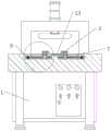
图1为本实用新型所述一种汽车发动机连杆生产用冲孔装置的结构示意图。FIG. 1 is a schematic structural diagram of a punching device for producing a connecting rod of an automobile engine according to the present invention.
图2为本实用新型所述一种汽车发动机连杆生产用冲孔装置的主视剖视结构示意图。FIG. 2 is a schematic cross-sectional structural schematic diagram of a front view of a punching device for producing a connecting rod of an automobile engine according to the present invention.
图3为本实用新型所述一种汽车发动机连杆生产用冲孔装置的侧视结构示意图。FIG. 3 is a schematic side view of the structure of a punching device for producing a connecting rod of an automobile engine according to the present invention.
图4为本实用新型图1所述一种汽车发动机连杆生产用冲孔装置的局部放大结构示意图。FIG. 4 is a partial enlarged structural schematic diagram of a punching device for producing a connecting rod of an automobile engine according to FIG. 1 of the present utility model.
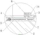
图5为本实用新型图2所述一种汽车发动机连杆生产用冲孔装置的局部放大结构示意图。FIG. 5 is a partial enlarged structural schematic diagram of a punching device for producing a connecting rod of an automobile engine according to FIG. 2 of the present utility model.
图中:1、冲孔机本体;2、操作台;3、底座;4、壳体;5、伺服电机;6、螺纹杆;7、滑块;8、加固块;9、旋转电机;10、打磨盘;11、支撑架;12、液压杆;13、伸缩杆;14、防滑垫。In the figure: 1. Punching machine body; 2. Operating table; 3. Base; 4. Housing; 5. Servo motor; 6. Threaded rod; 7. Slider; 8. Reinforcing block; 9. Rotary motor; 10 , grinding disc; 11, support frame; 12, hydraulic rod; 13, telescopic rod; 14, anti-skid pad.
具体实施方式Detailed ways
下面将结合本实用新型实施例中的附图,对本实用新型实施例中的技术方案进行清楚、完整地描述,显然,所描述的实施例仅仅是本实用新型一部分实施例,而不是全部的实施例。基于本实用新型中的实施例,本领域普通技术人员在没有做出创造性劳动前提下所获得的所有其他实施例,都属于本实用新型保护的范围。The technical solutions in the embodiments of the present utility model will be clearly and completely described below with reference to the accompanying drawings in the embodiments of the present utility model. Obviously, the described embodiments are only a part of the embodiments of the present utility model, rather than all the implementations. example. Based on the embodiments of the present invention, all other embodiments obtained by those of ordinary skill in the art without creative work fall within the protection scope of the present invention.
通过本领域人员,将本案中所有电气件与其适配的电源通过导线进行连接,并且应该根据实际情况,选择合适的控制器以及编码器,以满足控制需求,具体连接以及控制顺序,应参考下述工作原理中,各电气件之间先后工作顺序完成电性连接,其详细连接手段,为本领域公知技术,下述主要介绍工作原理以及过程,不再对电气控制做说明。All the electrical components in this case are connected with the power supply to which they are adapted through wires by those skilled in the art, and appropriate controllers and encoders should be selected according to the actual situation to meet the control requirements. For specific connections and control sequences, please refer to the following In the working principle described above, the electrical connection between the electrical components is completed in sequence, and the detailed connection method is known in the art. The following mainly introduces the working principle and process, and will not describe the electrical control.
实施例:本实用新型提供一种技术方案:根据说明书附图1-5可知,本案是一种汽车发动机连杆生产用冲孔装置,主要包括:冲孔机本体1、操作台2、底座3、一对结构相同的支撑结构以及辅助打磨部,连接关系如下:Embodiment: The utility model provides a technical solution: according to the accompanying drawings 1-5 of the description, this case is a punching device for the production of automobile engine connecting rods, which mainly includes:
操作台2固定安装于冲孔机本体1上,一对支撑结构固定安装于操作台2上,辅助打磨部嵌装于操作台2内部,且位于支撑结构后端,底座3嵌装于操作台2顶端,且固定安装于一对支撑架11构之间;The operating table 2 is fixedly installed on the
支撑结构包括:壳体4、伺服电机5、螺纹杆6、滑块7以及加固块8;The support structure includes: a
壳体4嵌装于操作台2内部,伺服电机5安装于壳体4内部,且与壳体4下壁面固定连接,螺纹杆6一端与伺服电机5驱动端固定连接,螺纹杆6另一端与壳体4内壁面活动连接,滑块7底端套装于螺纹杆6上,滑块7顶端延伸至壳体4外侧,加固块8固定安装于滑块7侧壁面上,加固块8一侧与底座3固定连接。The
通过上述总体情况可知,在使用的时候,通过冲孔机本体1对发动机连杆进行冲孔,通过操作台2对连杆以及支撑结构进行支撑,通过支撑结构对发动机连杆进行固定,通过辅助打磨结构对冲孔后的发动机连杆进行毛边打磨,通过壳体4对伺服电机5进行固定,启动伺服电机5,通过伺服电机5的转动带动螺纹杆6进行转动,通过螺纹杆6的转动带动滑块7沿螺纹杆6的方向进行移动,通过滑块7的移动带动加固块8进行移动,从而对发动机连杆进行支撑固定,防止在从孔过程中,连杆发生偏移等现象。It can be seen from the above general situation that when in use, the engine connecting rod is punched through the
作为优选方案,更进一步的,辅助打磨部包括:旋转电机9、打磨盘10、支撑架11以及液压杆12;As a preferred solution, further, the auxiliary grinding part includes: a rotary motor 9, a
液压杆12嵌装于操作台2内部,旋转电机9固定安装于液压杆12伸缩端上,打磨盘10底端与旋转电机9驱动端固定连接,支撑架11套装于打磨盘10底端,且与操作台2内壁面相贴合。The
通过上述情况可知,在使用的时候,启动液压杆12,通过液压杆12调节旋转电机9的高度,启动旋转电机9,通过旋转电机9的转动带动打磨盘10进行转动,从而对发动机连杆进行打磨,通过支撑架11对打磨盘10进行限位。It can be seen from the above situation that when in use, the
需要说明的是,在本文中,诸如第一和第二等之类的关系术语仅仅用来将一个实体或者操作与另一个实体或操作区分开来,而不一定要求或者暗示这些实体或操作之间存在任何这种实际的关系或者顺序。而且,术语“包括”、“包含”或者其任何其他变体意在涵盖非排他性的包含,从而使得包括一系列要素的过程、方法、物品或者设备不仅包括那些要素,而且还包括没有明确列出的其他要素,或者是还包括为这种过程、方法、物品或者设备所固有的要素,在没有更多限制的情况下,由语句“包括一个......限定的要素,并不排除在包括所述要素的过程、方法、物品或者设备中还存在另外的相同要素”。It should be noted that, in this document, relational terms such as first and second are only used to distinguish one entity or operation from another entity or operation, and do not necessarily require or imply any relationship between these entities or operations. any such actual relationship or sequence exists. Moreover, the terms "comprising", "comprising" or any other variation thereof are intended to encompass a non-exclusive inclusion such that a process, method, article or device that includes a list of elements includes not only those elements, but also includes not explicitly listed other elements, or also elements inherent to such a process, method, article or apparatus, without further limitation, an element qualified by the statement "including a... does not exclude There are additional identical elements in a process, method, article or apparatus that includes the stated elements".
尽管已经示出和描述了本实用新型的实施例,对于本领域的普通技术人员而言,可以理解在不脱离本实用新型的原理和精神的情况下可以对这些实施例进行多种变化、修改、替换和变型,本实用新型的范围由所附权利要求及其等同物限定。Although the embodiments of the present invention have been shown and described, it will be understood by those skilled in the art that various changes and modifications can be made to these embodiments without departing from the principles and spirit of the present invention , alternatives and modifications, the scope of the present invention is defined by the appended claims and their equivalents.
Claims (6)
Translated fromChinesePriority Applications (1)
| Application Number | Priority Date | Filing Date | Title |
|---|---|---|---|
| CN201921965876.4UCN210877204U (en) | 2019-11-14 | 2019-11-14 | A punching device for production of automobile engine connecting rod |
Applications Claiming Priority (1)
| Application Number | Priority Date | Filing Date | Title |
|---|---|---|---|
| CN201921965876.4UCN210877204U (en) | 2019-11-14 | 2019-11-14 | A punching device for production of automobile engine connecting rod |
Publications (1)
| Publication Number | Publication Date |
|---|---|
| CN210877204Utrue CN210877204U (en) | 2020-06-30 |
Family
ID=71311536
Family Applications (1)
| Application Number | Title | Priority Date | Filing Date |
|---|---|---|---|
| CN201921965876.4UActiveCN210877204U (en) | 2019-11-14 | 2019-11-14 | A punching device for production of automobile engine connecting rod |
Country Status (1)
| Country | Link |
|---|---|
| CN (1) | CN210877204U (en) |
Cited By (2)
| Publication number | Priority date | Publication date | Assignee | Title |
|---|---|---|---|---|
| CN115740102A (en)* | 2022-11-07 | 2023-03-07 | 白城中一精锻股份有限公司 | Shaping and pushing device for engine connecting rod |
| CN118237480A (en)* | 2024-05-27 | 2024-06-25 | 常州聚成锐传动科技有限公司 | Stamping forming equipment for manufacturing speed reducer shell |
- 2019
- 2019-11-14CNCN201921965876.4Upatent/CN210877204U/enactiveActive
Cited By (2)
| Publication number | Priority date | Publication date | Assignee | Title |
|---|---|---|---|---|
| CN115740102A (en)* | 2022-11-07 | 2023-03-07 | 白城中一精锻股份有限公司 | Shaping and pushing device for engine connecting rod |
| CN118237480A (en)* | 2024-05-27 | 2024-06-25 | 常州聚成锐传动科技有限公司 | Stamping forming equipment for manufacturing speed reducer shell |
Similar Documents
| Publication | Publication Date | Title |
|---|---|---|
| CN210877204U (en) | A punching device for production of automobile engine connecting rod | |
| CN206464958U (en) | A kind of bistrique moves back and forth polishing machine | |
| CN110014348A (en) | A kind of plank deburring equipment in wood furniture processing | |
| CN208788242U (en) | A kind of tempered glass edge grinding device | |
| CN210878978U (en) | An automobile engine connecting rod burr grinding device | |
| CN115592211A (en) | A gear tooth profile modification device used in a gear transmission | |
| CN210703964U (en) | Corrugated metal pipe polisher convenient to use | |
| CN113370048A (en) | Bolt surface clout clean-up equipment | |
| CN208431133U (en) | A kind of novel reciprocating type air compressor machine | |
| CN213559571U (en) | Automatically controlled cabinet body bender | |
| CN109352475B (en) | Fixed cushion block grinding device for ship base | |
| CN217684246U (en) | High-efficient suction equipment for industrial production pump | |
| CN218874824U (en) | Micro-motor shell machining pretreatment equipment | |
| CN107956728A (en) | A kind of head-shaking device and its method of work | |
| CN112981837A (en) | Broken hole processingequipment suitable for jeans production system | |
| CN209207120U (en) | A kind of grinding device for punching mold hole | |
| CN207915006U (en) | A CNC machining center for producing spherical parts | |
| CN207272965U (en) | A kind of deburring brush member | |
| CN208051603U (en) | The loading attachment of pneumatic Carving grinder | |
| CN202239421U (en) | Electric program control screw press for forging and pressing | |
| CN222945127U (en) | Polishing device capable of swinging in fan shape | |
| CN223146729U (en) | Piston cylinder inner wall grinding device | |
| CN221809181U (en) | Pump shaft machining polishing device | |
| CN210499622U (en) | Production grinding device of stainless steel wire packing ring | |
| CN220740269U (en) | Positioning tool for refrigerator refrigeration compressor machining |
Legal Events
| Date | Code | Title | Description |
|---|---|---|---|
| GR01 | Patent grant | ||
| GR01 | Patent grant | ||
| PE01 | Entry into force of the registration of the contract for pledge of patent right | Denomination of utility model:Punching device for automobile engine connecting rod production Effective date of registration:20220426 Granted publication date:20200630 Pledgee:China Postal Savings Bank Co.,Ltd. Liaocheng Chiping District sub branch Pledgor:Shandong brilliance connecting rod Co.,Ltd. Registration number:Y2022980004614 | |
| PE01 | Entry into force of the registration of the contract for pledge of patent right | ||
| PC01 | Cancellation of the registration of the contract for pledge of patent right | Granted publication date:20200630 Pledgee:China Postal Savings Bank Co.,Ltd. Liaocheng Chiping District sub branch Pledgor:Shandong brilliance connecting rod Co.,Ltd. Registration number:Y2022980004614 |