CN210866217U - Photovoltaic module - Google Patents
Photovoltaic moduleDownload PDFInfo
- Publication number
- CN210866217U CN210866217UCN202020105717.3UCN202020105717UCN210866217UCN 210866217 UCN210866217 UCN 210866217UCN 202020105717 UCN202020105717 UCN 202020105717UCN 210866217 UCN210866217 UCN 210866217U
- Authority
- CN
- China
- Prior art keywords
- layer
- solar cells
- sensitive adhesive
- photovoltaic module
- solar cell
- Prior art date
- Legal status (The legal status is an assumption and is not a legal conclusion. Google has not performed a legal analysis and makes no representation as to the accuracy of the status listed.)
- Active
Links
Images


Classifications
- Y—GENERAL TAGGING OF NEW TECHNOLOGICAL DEVELOPMENTS; GENERAL TAGGING OF CROSS-SECTIONAL TECHNOLOGIES SPANNING OVER SEVERAL SECTIONS OF THE IPC; TECHNICAL SUBJECTS COVERED BY FORMER USPC CROSS-REFERENCE ART COLLECTIONS [XRACs] AND DIGESTS
- Y02—TECHNOLOGIES OR APPLICATIONS FOR MITIGATION OR ADAPTATION AGAINST CLIMATE CHANGE
- Y02E—REDUCTION OF GREENHOUSE GAS [GHG] EMISSIONS, RELATED TO ENERGY GENERATION, TRANSMISSION OR DISTRIBUTION
- Y02E10/00—Energy generation through renewable energy sources
- Y02E10/50—Photovoltaic [PV] energy
Landscapes
- Photovoltaic Devices (AREA)
Abstract
Translated fromChinese
Description
Translated fromChinese技术领域technical field
本申请涉及光伏技术领域,特别是涉及一种光伏组件。The present application relates to the field of photovoltaic technology, and in particular, to a photovoltaic module.
背景技术Background technique
太阳能是一种取之不尽用之不竭的清洁能源,光伏组件是一种可以将太阳能转化为电能的器件,可以在一定程度上缓解能源危机。Solar energy is an inexhaustible clean energy, and photovoltaic modules are devices that can convert solar energy into electrical energy, which can alleviate the energy crisis to a certain extent.
光伏组件中含有多片太阳能电池,实现太阳能电池间的电路导通,目前是利用锡铅铜基焊带将一定数量的太阳能电池,经280℃~380℃高温焊接串焊在一起,再由多个焊接串按玻璃、EVA(ethylene-vinyl acetate copolymer,乙烯-醋酸乙烯共聚物)胶膜、电池层、EVA胶膜、背板层叠顺序依次层叠,经层压机层压,装框及焊接线盒等操作,完成光伏组件的制作。由于利用锡铅铜基焊带进行焊接时,太阳能电池受高温焊接产生的应力影响,容易弯曲,从而造成隐裂或后续层压后的电池碎片,对于尺寸加大化以及减薄化趋势的太阳能电池而言,隐裂以及碎片的状况更严重。Photovoltaic modules contain multiple solar cells to achieve circuit conduction between solar cells. At present, a certain number of solar cells are welded together by tin-lead-copper-based soldering tapes at a high temperature of 280 ° C ~ 380 ° C. Each welding string is laminated in the order of glass, EVA (ethylene-vinyl acetate copolymer, ethylene-vinyl acetate copolymer) film, battery layer, EVA film, backplane lamination sequence, lamination by laminator, frame and welding line Box and other operations to complete the production of photovoltaic modules. Due to the use of tin-lead-copper-based solder tape for soldering, the solar cell is easily bent due to the stress generated by high-temperature soldering, resulting in cracks or subsequent lamination of cell fragments. In the case of batteries, cracks and debris are more serious.
因此,如何解决太阳能电池的隐裂以及碎片的问题应是本领域技术人员重点关注的。Therefore, how to solve the problems of cracks and fragments of solar cells should be the focus of those skilled in the art.
实用新型内容Utility model content
本申请的目的是提供一种光伏组件,以降低太阳能电池出现隐裂或者碎片的情况,提升光伏组件的成品率。The purpose of the present application is to provide a photovoltaic module, so as to reduce the occurrence of cracks or fragments in the solar cell and improve the yield of the photovoltaic module.
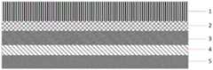
为解决上述技术问题,本申请提供一种光伏组件,包括由下至上依次层叠的基板、第一胶膜层、电池片层、第二胶膜层、玻璃基板;In order to solve the above technical problems, the present application provides a photovoltaic module, comprising a substrate, a first adhesive film layer, a cell sheet layer, a second adhesive film layer, and a glass substrate sequentially stacked from bottom to top;
所述电池片层包括多串电池串,每串所述电池串包括多片太阳能电池,且多片所述太阳能电池之间通过导电压敏胶带连接,所述导电压敏胶带包括基材层和导电压敏胶层。The battery sheet layer includes a plurality of strings of battery strings, each string of the battery strings includes a plurality of solar cells, and the plurality of the solar cells are connected by a conductive voltage-sensitive adhesive tape, and the conductive voltage-sensitive adhesive tape includes a substrate layer and a Conductive pressure sensitive adhesive layer.
可选的,当所述太阳能电池为常规太阳能电池或者叠焊太阳能电池时,所述导电压敏胶层分别位于所述基材层上表面的第一预设区域、下表面的第二预设区域,所述导电压敏胶层分别连接于相邻所述太阳能电池的上表面和下表面。Optionally, when the solar cell is a conventional solar cell or a stitch-bonded solar cell, the conductive voltage-sensitive adhesive layer is respectively located in a first preset area on the upper surface of the base material layer and a second preset area on the lower surface of the substrate layer. area, the conductive voltage-sensitive adhesive layer is respectively connected to the upper surface and the lower surface of the adjacent solar cells.
可选的,所述基板为玻璃板或者背板。Optionally, the substrate is a glass plate or a back plate.
可选的,当所述太阳能电池为IBC太阳能电池时,所述导电压敏胶层位于所述基材层的上表面。Optionally, when the solar cell is an IBC solar cell, the conductive pressure-sensitive adhesive layer is located on the upper surface of the substrate layer.
可选的,所述第一胶膜层和所述第二胶膜层均为EVA胶膜层或者均为POE胶膜层。Optionally, the first adhesive film layer and the second adhesive film layer are both EVA adhesive film layers or both POE adhesive film layers.
可选的,所述玻璃基板为超白压花玻璃。Optionally, the glass substrate is ultra-white patterned glass.
本申请所提供的光伏组件,包括由下至上依次层叠的基板、第一胶膜层、电池片层、第二胶膜层、玻璃基板;所述电池片层包括多串电池串,每串所述电池串包括多片太阳能电池,且多片所述太阳能电池之间通过导电压敏胶带连接,所述导电压敏胶带包括基材层和导电压敏胶层。可见,本申请光伏组件中太阳能电池之间通过导电压敏胶带进行连接,避免采用焊带进行连接,因此无需进行高温焊接,避免太阳能电池受到热应力,进而解决太阳能电池出现隐裂或者碎片概率,提升光伏组件的成品率,同时适用于太阳能电池向尺寸增大及电池厚度减薄趋势发展,由于导电压敏胶带具有粘性,可以直接揭开导电压敏胶带进行返修,非常方便。The photovoltaic module provided by the present application includes a substrate, a first adhesive film layer, a cell layer, a second adhesive film layer, and a glass substrate sequentially stacked from bottom to top; the cell sheet layer includes multiple strings of battery strings, and each string is The battery string includes a plurality of solar cells, and the plurality of solar cells are connected by a conductive voltage-sensitive adhesive tape, and the conductive voltage-sensitive adhesive tape includes a substrate layer and a conductive voltage-sensitive adhesive layer. It can be seen that in the photovoltaic module of the present application, the solar cells are connected by conductive voltage-sensitive tapes, avoiding the use of welding tapes for connection, so there is no need to perform high-temperature welding, so as to avoid thermal stress on the solar cells, thereby solving the probability of cracks or fragments in the solar cells, It improves the yield of photovoltaic modules, and is also suitable for the trend of solar cells increasing in size and thinning cell thickness. Due to the adhesiveness of the conductive voltage-sensitive tape, the conductive voltage-sensitive tape can be directly removed for repair, which is very convenient.
附图说明Description of drawings
为了更清楚的说明本申请实施例或现有技术的技术方案,下面将对实施例或现有技术描述中所需要使用的附图作简单的介绍,显而易见地,下面描述中的附图仅仅是本申请的一些实施例,对于本领域普通技术人员来讲,在不付出创造性劳动的前提下,还可以根据这些附图获得其他的附图。In order to illustrate the technical solutions of the embodiments of the present application or the prior art more clearly, the following briefly introduces the accompanying drawings that need to be used in the description of the embodiments or the prior art. Obviously, the drawings in the following description are only For some embodiments of the present application, for those of ordinary skill in the art, other drawings can also be obtained according to these drawings without any creative effort.
图1为本申请实施例所提供的一种光伏组件的结构示意图;FIG. 1 is a schematic structural diagram of a photovoltaic module provided by an embodiment of the application;
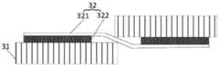
图2为本申请实施例所提供的一种常规太阳能电池间连接结构示意图;FIG. 2 is a schematic diagram of a conventional connection structure between solar cells according to an embodiment of the present application;
图3为本申请实施例所提供的一种导电压敏胶带的结构示意图;3 is a schematic structural diagram of a conductive voltage-sensitive adhesive tape provided by an embodiment of the application;
图4为本申请实施例所提供的一种叠焊太阳能电池间连接结构示意图;FIG. 4 is a schematic diagram of a connection structure between stitched solar cells according to an embodiment of the application;
图5为本申请实施例所提供的另一种导电压敏胶带的结构示意图;5 is a schematic structural diagram of another conductive voltage-sensitive adhesive tape provided by an embodiment of the application;
图6相邻IBC太阳能电池的连接结构示意图;FIG. 6 is a schematic diagram of the connection structure of adjacent IBC solar cells;
图中,1.玻璃基板,2.第二胶膜层,3.电池片层,4.第一胶膜层,5.基板,6.正电极,7.负电极,31.太阳能电池,32.导电压敏胶带,321.基材层,322.导电压敏胶层。In the figure, 1. Glass substrate, 2. Second adhesive film layer, 3. Cell layer, 4. First adhesive film layer, 5. Substrate, 6. Positive electrode, 7. Negative electrode, 31. Solar cell, 32 . Conductive voltage-sensitive tape, 321. Substrate layer, 322. Conductive voltage-sensitive adhesive layer.
具体实施方式Detailed ways
为了使本技术领域的人员更好地理解本申请方案,下面结合附图和具体实施方式对本申请作进一步的详细说明。显然,所描述的实施例仅仅是本申请一部分实施例,而不是全部的实施例。基于本申请中的实施例,本领域普通技术人员在没有做出创造性劳动前提下所获得的所有其他实施例,都属于本申请保护的范围。In order to make those skilled in the art better understand the solution of the present application, the present application will be further described in detail below with reference to the accompanying drawings and specific embodiments. Obviously, the described embodiments are only a part of the embodiments of the present application, but not all of the embodiments. Based on the embodiments in the present application, all other embodiments obtained by those of ordinary skill in the art without creative efforts shall fall within the protection scope of the present application.
在下面的描述中阐述了很多具体细节以便于充分理解本实用新型,但是本实用新型还可以采用其他不同于在此描述的其它方式来实施,本领域技术人员可以在不违背本实用新型内涵的情况下做类似推广,因此本实用新型不受下面公开的具体实施例的限制。In the following description, many specific details are set forth in order to fully understand the present utility model, but the present utility model can also be implemented in other ways different from those described herein, and those skilled in the art can do so without departing from the connotation of the present utility model. Therefore, the present invention is not limited by the specific embodiments disclosed below.
正如背景技术部分所述,现有技术的光伏组件中采用锡铅铜基焊带进行焊接,太阳能电池受高温焊接产生的应力影响,容易弯曲,从而造成隐裂或后续层压后的电池碎片,对于尺寸加大化以及减薄化趋势的太阳能电池而言,隐裂以及碎片的状况更严重。As mentioned in the background art section, the prior art photovoltaic modules are soldered with tin-lead-copper-based solder tapes, and the solar cells are easily bent due to the stress caused by high-temperature soldering, resulting in cracks or subsequent lamination of cell fragments. For solar cells with increasing size and thinning trends, the situation of cracks and chips is more serious.
有鉴于此,本申请提供了一种光伏组件,请参考图1和图2,图1为本申请实施例所提供的一种光伏组件的结构示意图,图2为本申请实施例所提供的一种常规太阳能电池间连接结构示意图,该光伏组件包括由下至上依次层叠的基板5、第一胶膜层4、电池片层3、第二胶膜层2、玻璃基板1;In view of this, the present application provides a photovoltaic assembly, please refer to FIG. 1 and FIG. 2 , FIG. 1 is a schematic structural diagram of a photovoltaic assembly provided by an embodiment of the present application, and FIG. 2 is a schematic diagram of a photovoltaic assembly provided by an embodiment of the present application. A schematic diagram of the connection structure between conventional solar cells, the photovoltaic assembly includes a
所述电池片层3包括多串电池串,每串所述电池串包括多片太阳能电池31,且多片所述太阳能电池31之间通过导电压敏胶带32连接,所述导电压敏胶带32包括基材层321和导电压敏胶层322。The cell layer 3 includes a plurality of strings of cells, each string of the cells includes a plurality of
可选的,当所述太阳能电池31为常规太阳能电池或者叠焊太阳能电池31时,所述导电压敏胶层322分别位于所述基材层321上表面的第一预设区域、下表面的第二预设区域,所述导电压敏胶层322分别连接于相邻所述太阳能电池31的上表面和下表面。Optionally, when the
具体的,请参见图3,图3为本申请实施例所提供的一种导电压敏胶带32的结构示意图,当太阳能电池31为常规太阳能电池或者叠焊太阳能电池31时,相邻太阳能电池31的连接结构示意图分别参见图2和图4。Specifically, please refer to FIG. 3 . FIG. 3 is a schematic structural diagram of a conductive voltage-sensitive
本实施例中导电压敏胶层322分别连接于相邻太阳能电池31的上表面和下表面,即当位于第一预设区域的导电压敏胶层322与一个太阳能电池31的上表面相连时,则位于第二预设区域的导电压敏胶层322与另一个太阳能电池31的下表面相连。In this embodiment, the conductive voltage-sensitive
需要指出的是,第一预设区域为基材层321上表面的局部区域,本实施例中对第一预设区域的具体大小不做具体限定,视情况而定。第二预设区域同理,此处不再详细赘述。It should be pointed out that the first preset area is a local area on the upper surface of the
可选的,当所述太阳能电池31为IBC太阳能电池31时,所述导电压敏胶层322位于所述基材层321的上表面,请参见图5和图6,图5为本申请实施例所提供的另一种导电压敏胶带32的结构示意图,图6相邻IBC太阳能电池31的连接结构示意图。Optionally, when the
IBC太阳能电池31的正电极6和负电极7均位于电池的背面,正电极6和负电极7在IBC电池的背面间隔平行设置,且列数相等,且相邻IBC电池的正电极6和负电极7排布顺序相反,导电压敏胶带32的导电压敏胶层322连接于相邻IBC电池的正电极6和负电极7。The positive electrode 6 and the negative electrode 7 of the IBC
优选地,当太阳能电池31为IBC太阳能电池时,正电极6和负电极7均为分段电极,可以节约银浆的用量,降低成本。Preferably, when the
需要说明的是,本实施例中对第一胶膜层4和第二胶膜层2的材料不做具体限定,视情况而定。例如,所述第一胶膜层4和所述第二胶膜层2均为EVA(Ethylene VinylAcetate,乙烯-醋酸乙烯共聚物)胶膜层或者均为POE(乙烯-辛稀共聚物)胶膜层。It should be noted that the materials of the first
本实施例光伏组件中太阳能电池31之间通过导电压敏胶带32进行连接,避免采用焊带进行连接,因此无需进行高温焊接,避免太阳能电池31受到热应力,进而解决太阳能电池31出现隐裂或者碎片概率,提升光伏组件的成品率,同时适用于太阳能电池31向尺寸增大及电池厚度减薄趋势发展,由于导电压敏胶带32具有粘性,可以直接揭开导电压敏胶带32进行返修,非常方便。In the photovoltaic module of this embodiment, the
可选的,在本申请的一个实施例中,所述基板5为玻璃板或者背板。其中,当光伏组件为单玻组件时,基板5为背板;当光伏组件为双玻组件时,基板5为玻璃板。进一步地,本实施例中对背板的材料不做具体限定,可以视情况而定。例如,背板可以为TPT、TPE、KPE等结构背板。Optionally, in an embodiment of the present application, the
在上述实施例的基础上,在本申请的一个实施例中,所述玻璃基板1为超白压花玻璃。超白压花玻璃具有透光率高、反射率低的特点,可以增加太阳光线透过玻璃基板1的数量,从而增加电池层吸收光线的数量,提升光伏组件的光电转换效率。On the basis of the above embodiment, in an embodiment of the present application, the glass substrate 1 is ultra-white patterned glass. Ultra-white patterned glass has the characteristics of high light transmittance and low reflectivity, which can increase the amount of sunlight passing through the glass substrate 1, thereby increasing the amount of light absorbed by the battery layer and improving the photoelectric conversion efficiency of photovoltaic modules.
本说明书中各个实施例采用递进的方式描述,每个实施例重点说明的都是与其它实施例的不同之处,各个实施例之间相同或相似部分互相参见即可。对于实施例公开的装置而言,由于其与实施例公开的方法相对应,所以描述的比较简单,相关之处参见方法部分说明即可。The various embodiments in this specification are described in a progressive manner, and each embodiment focuses on the differences from other embodiments, and the same or similar parts between the various embodiments may be referred to each other. As for the device disclosed in the embodiment, since it corresponds to the method disclosed in the embodiment, the description is relatively simple, and the relevant part can be referred to the description of the method.
以上对本申请所提供的光伏组件进行了详细介绍。本文中应用了具体个例对本申请的原理及实施方式进行了阐述,以上实施例的说明只是用于帮助理解本申请的方法及其核心思想。应当指出,对于本技术领域的普通技术人员来说,在不脱离本申请原理的前提下,还可以对本申请进行若干改进和修饰,这些改进和修饰也落入本申请权利要求的保护范围内。The photovoltaic modules provided by the present application have been introduced in detail above. Specific examples are used herein to illustrate the principles and implementations of the present application, and the descriptions of the above embodiments are only used to help understand the methods and core ideas of the present application. It should be pointed out that for those of ordinary skill in the art, without departing from the principles of the present application, several improvements and modifications can also be made to the present application, and these improvements and modifications also fall within the protection scope of the claims of the present application.
Claims (6)
Priority Applications (1)
| Application Number | Priority Date | Filing Date | Title |
|---|---|---|---|
| CN202020105717.3UCN210866217U (en) | 2020-01-17 | 2020-01-17 | Photovoltaic module |
Applications Claiming Priority (1)
| Application Number | Priority Date | Filing Date | Title |
|---|---|---|---|
| CN202020105717.3UCN210866217U (en) | 2020-01-17 | 2020-01-17 | Photovoltaic module |
Publications (1)
| Publication Number | Publication Date |
|---|---|
| CN210866217Utrue CN210866217U (en) | 2020-06-26 |
Family
ID=71287634
Family Applications (1)
| Application Number | Title | Priority Date | Filing Date |
|---|---|---|---|
| CN202020105717.3UActiveCN210866217U (en) | 2020-01-17 | 2020-01-17 | Photovoltaic module |
Country Status (1)
| Country | Link |
|---|---|
| CN (1) | CN210866217U (en) |
Cited By (1)
| Publication number | Priority date | Publication date | Assignee | Title |
|---|---|---|---|---|
| CN111976227A (en)* | 2020-08-05 | 2020-11-24 | 东方日升(义乌)新能源有限公司 | A single-cavity frameless laminated double-glass component and its lamination method |
- 2020
- 2020-01-17CNCN202020105717.3Upatent/CN210866217U/enactiveActive
Cited By (1)
| Publication number | Priority date | Publication date | Assignee | Title |
|---|---|---|---|---|
| CN111976227A (en)* | 2020-08-05 | 2020-11-24 | 东方日升(义乌)新能源有限公司 | A single-cavity frameless laminated double-glass component and its lamination method |
Similar Documents
| Publication | Publication Date | Title |
|---|---|---|
| CN105870216B (en) | A kind of connection structure with transparent electrode crystal silicon photovoltaic cell | |
| CN206907783U (en) | A kind of two-sided photovoltaic module | |
| CN110176506B (en) | Thin-film photovoltaic cell series structure and preparation process of thin-film photovoltaic cell series | |
| CN211428184U (en) | Solar cell panel and photovoltaic module | |
| EP4109743B1 (en) | Method for preparing a flexible and rollable back-contact solar cell module | |
| CN204834651U (en) | Solar module that low temperature concatenated | |
| CN102856425A (en) | Method for manufacturing soft silicon-based thin film solar cell integrated component | |
| CN110634978A (en) | A kind of double-sided power generation solar cell module and its preparation method | |
| CN113178501A (en) | Flexible photovoltaic module and preparation method thereof | |
| CN107958943A (en) | A kind of photovoltaic module and production method based on IBC cell packages | |
| CN106449798A (en) | Double-side light-inlet crystal silicon photovoltaic module and manufacturing method thereof | |
| WO2023202648A1 (en) | Photovoltaic module manufacturing method, and photovoltaic module | |
| CN205657073U (en) | Connection structure with transparent electrode crystalline silica photovoltaic cell | |
| CN107946382A (en) | Solar cell that MWT is combined with HIT and preparation method thereof | |
| CN207938625U (en) | A double-sided solar cell module | |
| CN210866217U (en) | Photovoltaic module | |
| CN109087961A (en) | A kind of photovoltaic module and preparation method thereof | |
| CN220382111U (en) | Back contact heterojunction solar cell and full-plane tile assembly | |
| CN210866216U (en) | An IBC battery pack | |
| CN108365043B (en) | Interconnection structure of photovoltaic cell piece subassembly | |
| CN218730981U (en) | Back electrode solar cell unit and battery module | |
| CN110718600A (en) | A kind of heterojunction battery and its component packaging structure | |
| CN207993882U (en) | A kind of interconnection architecture of photovoltaic cell component | |
| CN206322708U (en) | A kind of two-sided entering light crystalline silicon photovoltaic module | |
| CN111162136A (en) | A kind of IBC battery assembly and its production method |
Legal Events
| Date | Code | Title | Description |
|---|---|---|---|
| GR01 | Patent grant | ||
| GR01 | Patent grant |