CN210835223U - Sensor support, sensor assembly, movable object and vehicle - Google Patents
Sensor support, sensor assembly, movable object and vehicleDownload PDFInfo
- Publication number
- CN210835223U CN210835223UCN201921595894.8UCN201921595894UCN210835223UCN 210835223 UCN210835223 UCN 210835223UCN 201921595894 UCN201921595894 UCN 201921595894UCN 210835223 UCN210835223 UCN 210835223U
- Authority
- CN
- China
- Prior art keywords
- air curtain
- lidar
- air
- sensor
- cover
- Prior art date
- Legal status (The legal status is an assumption and is not a legal conclusion. Google has not performed a legal analysis and makes no representation as to the accuracy of the status listed.)
- Active
Links
Images


Classifications
- A—HUMAN NECESSITIES
- A01—AGRICULTURE; FORESTRY; ANIMAL HUSBANDRY; HUNTING; TRAPPING; FISHING
- A01M—CATCHING, TRAPPING OR SCARING OF ANIMALS; APPARATUS FOR THE DESTRUCTION OF NOXIOUS ANIMALS OR NOXIOUS PLANTS
- A01M29/00—Scaring or repelling devices, e.g. bird-scaring apparatus
- A01M29/30—Scaring or repelling devices, e.g. bird-scaring apparatus preventing or obstructing access or passage, e.g. by means of barriers, spikes, cords, obstacles or sprinkled water
- A01M29/34—Scaring or repelling devices, e.g. bird-scaring apparatus preventing or obstructing access or passage, e.g. by means of barriers, spikes, cords, obstacles or sprinkled water specially adapted for insects
- B—PERFORMING OPERATIONS; TRANSPORTING
- B60—VEHICLES IN GENERAL
- B60S—SERVICING, CLEANING, REPAIRING, SUPPORTING, LIFTING, OR MANOEUVRING OF VEHICLES, NOT OTHERWISE PROVIDED FOR
- B60S1/00—Cleaning of vehicles
- B60S1/62—Other vehicle fittings for cleaning
- G—PHYSICS
- G01—MEASURING; TESTING
- G01S—RADIO DIRECTION-FINDING; RADIO NAVIGATION; DETERMINING DISTANCE OR VELOCITY BY USE OF RADIO WAVES; LOCATING OR PRESENCE-DETECTING BY USE OF THE REFLECTION OR RERADIATION OF RADIO WAVES; ANALOGOUS ARRANGEMENTS USING OTHER WAVES
- G01S17/00—Systems using the reflection or reradiation of electromagnetic waves other than radio waves, e.g. lidar systems
- G01S17/88—Lidar systems specially adapted for specific applications
- G01S17/93—Lidar systems specially adapted for specific applications for anti-collision purposes
- G01S17/931—Lidar systems specially adapted for specific applications for anti-collision purposes of land vehicles
- G—PHYSICS
- G01—MEASURING; TESTING
- G01S—RADIO DIRECTION-FINDING; RADIO NAVIGATION; DETERMINING DISTANCE OR VELOCITY BY USE OF RADIO WAVES; LOCATING OR PRESENCE-DETECTING BY USE OF THE REFLECTION OR RERADIATION OF RADIO WAVES; ANALOGOUS ARRANGEMENTS USING OTHER WAVES
- G01S7/00—Details of systems according to groups G01S13/00, G01S15/00, G01S17/00
- G01S7/48—Details of systems according to groups G01S13/00, G01S15/00, G01S17/00 of systems according to group G01S17/00
- G01S7/481—Constructional features, e.g. arrangements of optical elements
- G01S7/4811—Constructional features, e.g. arrangements of optical elements common to transmitter and receiver
- G01S7/4813—Housing arrangements
- G—PHYSICS
- G01—MEASURING; TESTING
- G01S—RADIO DIRECTION-FINDING; RADIO NAVIGATION; DETERMINING DISTANCE OR VELOCITY BY USE OF RADIO WAVES; LOCATING OR PRESENCE-DETECTING BY USE OF THE REFLECTION OR RERADIATION OF RADIO WAVES; ANALOGOUS ARRANGEMENTS USING OTHER WAVES
- G01S7/00—Details of systems according to groups G01S13/00, G01S15/00, G01S17/00
- G01S7/48—Details of systems according to groups G01S13/00, G01S15/00, G01S17/00 of systems according to group G01S17/00
- G01S7/497—Means for monitoring or calibrating
- G01S2007/4975—Means for monitoring or calibrating of sensor obstruction by, e.g. dirt- or ice-coating, e.g. by reflection measurement on front-screen
- G01S2007/4977—Means for monitoring or calibrating of sensor obstruction by, e.g. dirt- or ice-coating, e.g. by reflection measurement on front-screen including means to prevent or remove the obstruction
Landscapes
- Engineering & Computer Science (AREA)
- Life Sciences & Earth Sciences (AREA)
- Physics & Mathematics (AREA)
- Computer Networks & Wireless Communication (AREA)
- General Physics & Mathematics (AREA)
- Radar, Positioning & Navigation (AREA)
- Remote Sensing (AREA)
- Insects & Arthropods (AREA)
- Pest Control & Pesticides (AREA)
- Electromagnetism (AREA)
- Birds (AREA)
- Wood Science & Technology (AREA)
- Zoology (AREA)
- Environmental Sciences (AREA)
- Mechanical Engineering (AREA)
- Optical Radar Systems And Details Thereof (AREA)
- Traffic Control Systems (AREA)
Abstract
Translated fromChinese
Description
Translated fromChinese技术领域technical field
本申请涉及自动驾驶技术领域,尤其涉及一种传感器支架、传感器组件、可移动物体及车辆。The present application relates to the technical field of autonomous driving, and in particular, to a sensor bracket, a sensor assembly, a movable object and a vehicle.
背景技术Background technique
当前,自动驾驶技术得到了很好的发展。目前的自动驾驶技术一般采用激光雷达、摄像头、毫米波雷达、超声波雷达等设备来感知外部环境,并根据外部环境来控制车辆行驶(如加速、减速、变道以及停车等操作)。At present, autonomous driving technology has been well developed. Current autonomous driving technologies generally use devices such as lidar, cameras, millimeter-wave radar, and ultrasonic radar to perceive the external environment, and control the vehicle’s driving (such as acceleration, deceleration, lane change, and parking) according to the external environment.
在很多情况下,为了更好的感知周围的物体,激光雷达一般安装在激光雷达支架上并伸出驾驶室两侧,同样的摄像头一般安装在摄像头支架上也伸出驾驶室两侧。激光雷达和摄像头等传感器对于车辆前部的感知尤为重要。然而,在野外一些蚊虫较多得地区,车辆在高速行驶时,蚊虫可能被车辆撞击,而粘附在激光雷达和摄像头等传感器上,从而影响到传感器的感知。In many cases, in order to better perceive the surrounding objects, the lidar is generally installed on the lidar bracket and protrudes from both sides of the cab, and the same camera is generally installed on the camera bracket and extends out of both sides of the cab. Sensors such as lidar and cameras are especially important for perception of the front of the vehicle. However, in some areas where there are many mosquitoes in the wild, when the vehicle is driving at high speed, the mosquitoes may be hit by the vehicle and stick to sensors such as lidar and cameras, thus affecting the perception of the sensor.
发明内容SUMMARY OF THE INVENTION
本申请的实施例提供一种传感器支架、传感器组件、可移动物体及车辆,能够避免车辆等可移动物体在高速行进时,有蚊虫撞击并粘附在传感器上,影响传感器的感知的问题。Embodiments of the present application provide a sensor bracket, a sensor assembly, a movable object, and a vehicle, which can avoid the problem that when a movable object such as a vehicle travels at a high speed, mosquitoes collide with and adhere to the sensor, affecting the perception of the sensor.
为达到上述目的,本申请采用如下技术方案:To achieve the above object, the application adopts the following technical solutions:
在本申请的第一方面,提供一种传感器支架,包括支架本体,所述支架本体的一端固定连接可移动物体,所述支架本体的另一端固定连接传感器;所述支架本体的另一端还设置有一至多个风幕机,所述一至多个风幕机设置于传感器的一至多侧,且所述风幕机的排风口朝向可移动物体移动时传感器的前侧迎风部。In a first aspect of the present application, a sensor support is provided, including a support body, one end of the support body is fixedly connected to a movable object, and the other end of the support body is fixedly connected to a sensor; the other end of the support body is further provided with There are one or more air curtains, the one or more air curtains are arranged on one or more sides of the sensor, and the air outlet of the air curtain is toward the front windward part of the sensor when the movable object moves.
在本申请的第二方面,提供一种传感器组件,包括传感器和传感器支架;所述传感器支架包括支架本体,所述支架本体的一端固定连接可移动物体,所述支架本体的另一端固定连接传感器;所述支架本体的另一端还设置有一至多个风幕机,所述一至多个风幕机设置于传感器的一至多侧,且所述风幕机的排风口朝向可移动物体移动时传感器的前侧迎风部。In a second aspect of the present application, a sensor assembly is provided, including a sensor and a sensor support; the sensor support includes a support body, one end of the support body is fixedly connected to a movable object, and the other end of the support body is fixedly connected to a sensor ; The other end of the bracket body is also provided with one or more air curtains, and the one or more air curtains are arranged on one or more sides of the sensor, and the exhaust port of the air curtain moves toward the movable object when the sensor moves the front windward.
在本申请的第三方面,提供一种可移动物体,所述可移动物体安装有如上述第二方面所述的传感器组件。In a third aspect of the present application, a movable object is provided, the movable object is mounted with the sensor assembly according to the above-mentioned second aspect.
在本申请的第四方面,提供一种车辆,所述车辆安装有如上述第二方面所述的传感器组件。In a fourth aspect of the present application, there is provided a vehicle mounted with the sensor assembly of the second aspect above.
本申请实施例提供的一种传感器支架、传感器组件、可移动物体及车辆,通过在传感器的前侧迎风部形成风幕,可以有效避免车辆等可移动物体在高速行进时,有蚊虫撞击并粘附在传感器上,影响传感器的感知。In a sensor bracket, a sensor assembly, a movable object, and a vehicle provided by the embodiments of the present application, by forming an air curtain on the windward part of the front side of the sensor, it is possible to effectively prevent the movable objects such as vehicles from being hit by mosquitoes and sticking to them when moving at high speed. Attached to the sensor, affects the perception of the sensor.
附图说明Description of drawings
为了更清楚地说明本申请实施例或现有技术中的技术方案,下面将对实施例或现有技术描述中所需要使用的附图作简单地介绍,显而易见地,下面描述中的附图仅仅是本申请的一些实施例,对于本领域普通技术人员来讲,在不付出创造性劳动性的前提下,还可以根据这些附图获得其他的附图。In order to more clearly illustrate the embodiments of the present application or the technical solutions in the prior art, the following briefly introduces the accompanying drawings required for the description of the embodiments or the prior art. Obviously, the drawings in the following description are only These are some embodiments of the present application, and for those of ordinary skill in the art, other drawings can also be obtained from these drawings without any creative effort.
图1为自动驾驶卡车上的传感器以及传感器支架的示意图;Figure 1 is a schematic diagram of a sensor and a sensor bracket on an autonomous truck;
图2为本申请实施例中蚊虫撞死在激光雷达的玻璃屏上,对激光雷达形成遮挡的示意图;FIG. 2 is a schematic diagram illustrating that a mosquito hits and dies on a glass screen of a lidar and blocks the lidar in an embodiment of the present application;
图3为本申请实施例中蚊虫撞死在摄像头的镜头表面,对摄像头形成遮挡的示意图;3 is a schematic diagram of a mosquito colliding to death on a lens surface of a camera and blocking the camera according to an embodiment of the present application;
图4为本申请实施例提供的一种传感器支架的结构示意图一;FIG. 4 is a schematic structural diagram 1 of a sensor support provided by an embodiment of the present application;
图5为本申请实施例提供的一种传感器支架的结构示意图二;FIG. 5 is a second structural schematic diagram of a sensor support provided by an embodiment of the present application;
图6为本申请实施例提供的一种传感器支架的结构示意图三;FIG. 6 is a third structural schematic diagram of a sensor support provided by an embodiment of the present application;
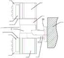
图7为本申请实施例提供的一种传感器支架的结构示意图四;FIG. 7 is a fourth schematic structural diagram of a sensor support provided by an embodiment of the present application;
图8为本申请实施例提供的一种传感器支架的爆炸结构示意图;8 is a schematic diagram of an exploded structure of a sensor support provided by an embodiment of the present application;
图9为本申请实施例提供的一种传感器支架的结构示意图五;FIG. 9 is a schematic structural diagram 5 of a sensor support provided in an embodiment of the present application;
图10为本申请实施例提供的一种传感器支架的结构示意图六;FIG. 10 is a sixth structural schematic diagram of a sensor support provided by an embodiment of the application;
图11为本申请实施例提供的一种传感器支架的结构示意图七;FIG. 11 is a seventh structural schematic diagram of a sensor support provided by an embodiment of the application;
图12为本申请实施例提供的一种传感器支架的结构示意图八;FIG. 12 is a schematic structural diagram eight of a sensor bracket provided by an embodiment of the present application;
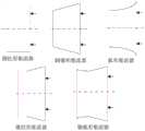
图13为本申请实施例提供的各类型集流器的示意图。FIG. 13 is a schematic diagram of various types of current collectors provided in an embodiment of the present application.
具体实施方式Detailed ways
下面将结合本申请实施例中的附图,对本申请实施例中的技术方案进行清楚、完整地描述,显然,所描述的实施例仅仅是本申请一部分实施例,而不是全部的实施例。基于本申请中的实施例,本领域普通技术人员在没有做出创造性劳动前提下所获得的所有其他实施例,都属于本申请保护的范围。The technical solutions in the embodiments of the present application will be clearly and completely described below with reference to the drawings in the embodiments of the present application. Obviously, the described embodiments are only a part of the embodiments of the present application, but not all of the embodiments. Based on the embodiments in the present application, all other embodiments obtained by those of ordinary skill in the art without creative efforts shall fall within the protection scope of the present application.
需要说明的是,本申请的说明书和权利要求书及上述附图中的术语“第一”、“第二”等是用于区别类似的对象,而不必用于描述特定的顺序或先后次序。应该理解这样使用的数据在适当情况下可以互换,以便这里描述的本申请的实施例。此外,术语“包括”和“具有”以及他们的任何变形,意图在于覆盖不排他的包含,例如,包含了一系列步骤或单元的过程、方法、系统、产品或设备不必限于清楚地列出的那些步骤或单元,而是可包括没有清楚地列出的或对于这些过程、方法、产品或设备固有的其它步骤或单元。It should be noted that the terms "first", "second", etc. in the description and claims of the present application and the above drawings are used to distinguish similar objects, and are not necessarily used to describe a specific sequence or sequence. It is to be understood that the data so used are interchangeable under appropriate circumstances for the embodiments of the application described herein. Furthermore, the terms "comprising" and "having" and any variations thereof, are intended to cover non-exclusive inclusion, for example, a process, method, system, product or device comprising a series of steps or units is not necessarily limited to those expressly listed Rather, those steps or units may include other steps or units not expressly listed or inherent to these processes, methods, products or devices.
在本申请的一些实施例中,术语“车辆”广泛地解释为包括任何移动物体,包括例如飞行器、船只、航天器、汽车、卡车、厢式货车、半挂车、摩托车、高尔夫球车、越野车辆、仓库运输车辆或农用车以及行驶在轨道上的运输工具,例如电车或火车以及其它有轨车辆。本申请中的“车辆”通常可以包括:动力系统、传感器系统、控制系统、外围设备和计算机系统。在其它实施例中,车辆可以包括更多、更少或者不同的系统。In some embodiments of the present application, the term "vehicle" is to be construed broadly to include any moving object including, for example, aircraft, watercraft, spacecraft, automobiles, trucks, vans, semi-trailers, motorcycles, golf carts, off-road vehicles Vehicles, warehouse transport vehicles or agricultural vehicles and means of transport on tracks, such as trams or trains and other rail vehicles. A "vehicle" in this application may generally include: power systems, sensor systems, control systems, peripherals, and computer systems. In other embodiments, the vehicle may include more, fewer, or different systems.
其中,动力系统是为车辆提供动力运动的系统,包括:引擎/马达、变速器和车轮/轮胎、能源单元。Among them, the power system is the system that provides power movement for the vehicle, including: engine/motor, transmission and wheel/tire, energy unit.
控制系统可以包括控制车辆及其组件的装置的组合,例如转向单元、节气门、制动单元。The control system may include a combination of devices that control the vehicle and its components, such as steering units, throttles, braking units.
外围设备可以是允许车辆与外部传感器、其它车辆、外部计算设备和/或用户进行交互的设备,例如无线通信系统、触摸屏、麦克风和/或扬声器。Peripherals may be devices that allow the vehicle to interact with external sensors, other vehicles, external computing devices, and/or the user, such as wireless communication systems, touch screens, microphones, and/or speakers.
基于上述描述的车辆,无人驾驶车辆中还配置有传感器系统和无人驾驶控制装置。Based on the vehicle described above, the unmanned vehicle is also equipped with a sensor system and an unmanned control device.
传感器系统可以包括用于感测车辆所处环境的信息的多个传感器,以及改变传感器的位置和/或方向的一个或多个致动器。传感器系统可以包括全球定位系统传感器、惯性测量单元、无线电检测和测距(RADAR)单元、相机、激光测距仪、光检测和测距(LIDAR)单元和/或声学传感器等传感器的任何组合;传感器系统还可以包括监视车辆内部系统的传感器(例如O2监视器、燃油表、引擎温度计等)。The sensor system may include a plurality of sensors for sensing information about the environment in which the vehicle is located, and one or more actuators for changing the position and/or orientation of the sensors. The sensor system may include any combination of sensors such as GPS sensors, inertial measurement units, radio detection and ranging (RADAR) units, cameras, laser rangefinders, light detection and ranging (LIDAR) units, and/or acoustic sensors; The sensor system may also include sensors that monitor systems inside the vehicle (eg,O2 monitors, fuel gauges, engine thermometers, etc.).
无人驾驶控制装置可以包括一个处理器和存储器,存储器中存储有至少一条机器可执行指令,处理器执行至少一条机器可执行指令实现包括地图引擎、定位模块、感知模块、导航或路径模块、以及自动控制模块等的功能。地图引擎和定位模块用于提供地图信息和定位信息。感知模块用于根据传感器系统获取到的信息和地图引擎提供的地图信息感知车辆所处环境中的事物。导航或路径模块用于根据地图引擎、定位模块和感知模块的处理结果,为车辆规划行驶路径。自动控制模块将导航或路径模块等模块的决策信息输入解析转换成对车辆控制系统的控制命令输出,并通过车载网(例如通过CAN总线、局域互联网络、多媒体定向系统传输等方式实现的车辆内部电子网络系统)将控制命令发送给车辆控制系统中的对应部件,实现对车辆的自动控制;自动控制模块还可以通过车载网来获取车辆中各部件的信息。The unmanned driving control device may include a processor and a memory, the memory stores at least one machine-executable instruction, and the processor executes the at least one machine-executable instruction to implement a map engine, a positioning module, a perception module, a navigation or path module, and Functions of automatic control modules, etc. The map engine and positioning module are used to provide map information and positioning information. The perception module is used to perceive things in the environment where the vehicle is located according to the information obtained by the sensor system and the map information provided by the map engine. The navigation or route module is used to plan the driving route for the vehicle according to the processing results of the map engine, the positioning module and the perception module. The automatic control module converts the decision information input and analysis of modules such as navigation or route modules into control command output for the vehicle control system, and implements the vehicle through the in-vehicle network (for example, through CAN bus, local area interconnection network, multimedia directional system transmission, etc.). The internal electronic network system) sends control commands to the corresponding components in the vehicle control system to realize automatic control of the vehicle; the automatic control module can also obtain the information of each component in the vehicle through the vehicle network.
在实现本申请实施例的过程中,发明人发现,如图1所示,在自动驾驶车辆,特别是自动驾驶卡车10上,激光雷达和摄像头越来越成为不可缺少的传感元件。为了达到良好的传感器采集效果,通过需要将激光雷达101布置在车身左右两侧的激光雷达支架102上以便于观察车身周边的环境。另外,车辆的摄像头支架104两侧还可以设置前向摄像头105,以采集车辆前方的图像。在一些地区,高速路上常常会有成群的蚊虫,当车辆高速行驶的时候,蚊虫来不及闪躲,会撞死在传感器的表面,例如图2所示的蚊虫20撞死在激光雷达101的玻璃屏上,对激光雷达101形成遮挡,对激光雷达101的成像造成影响;又例如图3所示的蚊虫20撞死在摄像头105的镜头表面,对摄像头105形成遮挡。而且当车辆在高速路上行驶时,无法停车对粘在传感器上的蚊虫尸体进行清理,等车辆到达目的地后,需要清洁人员用专门的清洗液来清理,造成传感器的清洁维护上的不便。而在车辆上增加防虫网等措施同样会对传感器造成遮挡。可见,目前并没有很好的方案来清理或避免蚊虫撞上车辆上的传感器。In the process of implementing the embodiments of the present application, the inventors found that, as shown in FIG. 1 , on an autonomous vehicle, especially an
为了解决上述缺陷,如图4所示,本申请实施例提供一种传感器支架30,包括支架本体31,该支架本体31的一端固定连接可移动物体40,支架本体31的另一端固定连接传感器32;支架本体31的另一端还设置有一至多个风幕机33(图4中仅以描绘了一个风幕机,但不仅局限于此,实际应用时,在传感器32的上下左右侧均可以设置风幕机),一至多个风幕机33设置于传感器32的一至多侧(图4中仅以一个风幕机在传感器32上侧为例,但不仅局限于此),且风幕机33的排风口331朝向可移动物体40移动时传感器32的前侧迎风部321。这样,通过在传感器的前侧迎风部形成风幕,可以有效避免车辆等可移动物体在高速行进时,有蚊虫撞击并粘附在传感器上,影响传感器的感知。In order to solve the above defects, as shown in FIG. 4 , an embodiment of the present application provides a
此处的传感器32可以为激光雷达322,也可以为摄像头323,但不仅局限于此,还可以是其他自动驾驶领域中的传感器。The sensor 32 here can be a
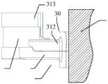
另外,在本申请的一实施例中,如图5所示,传感器32为激光雷达322;支架本体31包括激光雷达下安装罩壳311、激光雷达上安装罩壳312和激光雷达上护壳313;激光雷达下安装罩壳311设置在激光雷达322下侧以托起该激光雷达322,激光雷达上安装罩壳312设置在激光雷达322后侧;激光雷达上安装罩壳312与激光雷达下安装罩壳311闭合安装,并在远离激光雷达322的一侧与可移动物体40连接;激光雷达上护壳313连接在激光雷达上安装罩壳312上(例如通过螺栓连接,但不仅局限于此),且设置于激光雷达322上侧,激光雷达上护壳313与激光雷达下安装罩壳311配合将激光雷达322固定在激光雷达上护壳313与激光雷达下安装罩壳311之间的空间中。激光雷达上护壳313与激光雷达下安装罩壳311之间的空间需要露出激光雷达322的感知区域。In addition, in an embodiment of the present application, as shown in FIG. 5 , the sensor 32 is a
另外,在本申请的一实施例中,风幕机33可以设置于激光雷达322上侧,如图6所示,支架本体31的另一端设置有一个风幕机33;风幕机33设置于激光雷达322上侧,且风幕机33的排风口331向下朝向激光雷达322的前侧迎风部321。这样,风幕机33能够向下产生高速气流,将前侧迎风部321的异物,如蚊虫、沙泥、雨水等吹离,避免异物撞击和粘附在激光雷达322上。In addition, in an embodiment of the present application, the
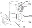
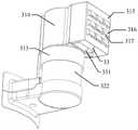
另外,在本申请的一实施例中,如图7和图8所示,在激光雷达上护壳313上端连接设置有风幕机安装罩壳314,风幕机33设置在风幕机安装罩壳314外侧;在风幕机33外侧设置有风幕机防护罩315;风幕机防护罩315与风幕机安装罩壳314配合将风幕机33包围;风幕机防护罩315在风幕机33的排风口331处设置有开口。这样,该风幕机安装罩壳314的整体位置是位于激光雷达322的上方,因此对激光雷达322同样起到了保护作用。In addition, in an embodiment of the present application, as shown in FIG. 7 and FIG. 8 , an air
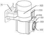
另外,在本申请的一实施例中,风幕机33可以设置于激光雷达322下侧,如图9所示,该支架本体31的另一端设置有一个风幕机33;该风幕机33设置于激光雷达322下侧,且风幕机33的排风口331向上朝向激光雷达322的前侧迎风部321。这样,风幕机33能够向上产生高速气流,将前侧迎风部321的异物,如蚊虫、沙泥、雨水等吹离,避免异物撞击和粘附在激光雷达322上。In addition, in an embodiment of the present application, the
另外,在本申请的一实施例中,如图10所示,在激光雷达下安装罩壳311下端连接设置有风幕机安装罩壳314,风幕机33设置在风幕机安装罩壳314外侧;在风幕机33外侧设置有风幕机防护罩315;风幕机防护罩315与风幕机安装罩壳314配合将风幕机33包围,风幕机防护罩315在风幕机33的排风口331处设置有开口。In addition, in an embodiment of the present application, as shown in FIG. 10 , the lower end of the
另外,在本申请的一实施例中,如图11所示,支架本体31的另一端可以设置有两个风幕机33和33’;其中一个风幕机33设置于激光雷达322上侧,且该一个风幕机33的排风口331向下朝向激光雷达322的前侧迎风部321;其中另一个风幕机33’设置于激光雷达322下侧,且另一个风幕机33’的排风口331’向上朝向激光雷达322的前侧迎风部321。这样,两个风幕机能够分别向上和向下产生高速气流,将前侧迎风部321的异物,如蚊虫、沙泥、雨水等吹离,避免异物撞击和粘附在激光雷达322上。In addition, in an embodiment of the present application, as shown in FIG. 11 , the other end of the
另外,在本申请的一实施例中,如图12所示,在激光雷达上护壳313上端连接设置有一个风幕机安装罩壳314,该一个风幕机33设置在一个风幕机安装罩壳314外侧;在一个风幕机33外侧设置有一个风幕机防护罩315;该一个风幕机防护罩315与一个风幕机安装罩壳314配合将一个风幕机33包围;该一个风幕机防护罩315在该一个风幕机33的排风口331处设置有开口。另外,在激光雷达下安装罩壳311下端连接设置有另一个风幕机安装罩壳314’,另一个风幕机33’设置在另一个风幕机安装罩壳314’外侧;在另一个风幕机33’外侧设置有另一个风幕机防护罩315’;另一个风幕机防护罩315’与另一个风幕机安装罩壳314’配合将另一个风幕机33’包围,另一个风幕机防护罩315’在另一个风幕机33’的排风口331’处设置有开口。In addition, in an embodiment of the present application, as shown in FIG. 12 , an air
另外,在本申请的一实施例中,如图7和图10所示,上述风幕机防护罩315外侧设置有多个防水透气孔316。例如,该多个防水透气孔316在风幕机防护罩外侧呈多个凸起结构,每个凸起结构的下侧设置有通孔317。这样,该通孔317向下,既可以避免防止雨水进入风幕机防护罩315,起到保护风幕机的作用,又可以起到为风幕机33补充空气的作用。In addition, in an embodiment of the present application, as shown in FIG. 7 and FIG. 10 , a plurality of waterproof ventilation holes 316 are provided on the outside of the above-mentioned air curtain
另外,如图7和图10所示,排风口331和风幕机防护罩315设置的开口为条形,例如为长方条形,或者长圆条形,但不仅局限于此。将开口设置为长方条形或长圆条形,可以有利于气流的聚集,更有利于高速气流的形成。In addition, as shown in FIG. 7 and FIG. 10 , the openings of the
另外,如图10所示,排风口331处设置有挡板318(该图7中的排风口331处同样可以设置挡板,图7中未示出),挡板318在排风口331出风时能够被推开,在排风口331未出风时能够闭合。该挡板318例如可以通过轻质弹簧或轻质弹片等方式连接在排风口处,这样在排风口出风时,可以被风直接推开,在无风时,又会因为轻质弹簧或轻质弹片的弹力而闭合。这样,该挡板可以在无风时保护风幕机,避免沙泥、雨水、蚊虫等进入到风幕机内部,影响后续风幕机的工作。In addition, as shown in FIG. 10 , a
另外,如图6和图9所示,风幕机33可以包括电机332和风机叶轮333;电机332带动风机叶轮333旋转,在风机叶轮333的叶片之间的气体也会跟着旋转,并在离心力的作用下甩出这些气体,气体流速增大,使气体在流动中把动能转换为静压能,然后随着流体的增压,使静压能又转换为速度能,通过排风口排除气体,在排风口331产生气流(例如气流速度大于20m/s,即可较为容易的将异物吹离),使得在激光雷达322的前侧迎风部321形成风幕;该风幕的宽度大于或等于激光雷达322的宽度,从而可以将撞向激光雷达322的蚊虫、沙泥、雨水等异物吹离,可以有效阻止异物撞击和粘附在激光雷达322表面。In addition, as shown in FIGS. 6 and 9 , the
另外,在排风口331处可以设置有集流器319,该集流器319能够增加排风口331形成的风幕的风速。例如如图13所示,该集流器319可以为圆柱形、圆锥形、弧形、锥柱形或锥弧形等,但不仅局限于此。In addition, a current collector 319 may be provided at the
在本申请的一实施例中,如图4所示,还提供一种传感器组件50,包括传感器32和传感器支架30;该传感器支架30,包括支架本体31,该支架本体31的一端固定连接可移动物体40,支架本体31的另一端固定连接传感器32;支架本体31的另一端还设置有一至多个风幕机33,一至多个风幕机33设置于传感器32的一至多侧,且风幕机33的排风口331朝向可移动物体40移动时传感器32的前侧迎风部321。这样,通过在传感器的前侧迎风部形成风幕,可以有效避免车辆等可移动物体在高速行进时,有蚊虫撞击并粘附在传感器上,影响传感器的感知。In an embodiment of the present application, as shown in FIG. 4 , a sensor assembly 50 is further provided, including a sensor 32 and a
此处的传感器32可以为激光雷达322,也可以为摄像头323,但不仅局限于此,还可以是其他自动驾驶领域中的传感器。The sensor 32 here can be a
另外,在本申请的一实施例中,如图5所示,传感器32为激光雷达322;支架本体31包括激光雷达下安装罩壳311、激光雷达上安装罩壳312和激光雷达上护壳313;激光雷达下安装罩壳311设置在激光雷达322下侧以托起该激光雷达322,激光雷达上安装罩壳312设置在激光雷达322后侧;激光雷达上安装罩壳312与激光雷达下安装罩壳311闭合安装,并在远离激光雷达322的一侧与可移动物体40连接;激光雷达上护壳313连接在激光雷达上安装罩壳312上(例如通过螺栓连接,但不仅局限于此),且设置于激光雷达322上侧,激光雷达上护壳313与激光雷达下安装罩壳311配合将激光雷达322固定在激光雷达上护壳313与激光雷达下安装罩壳311之间的空间中。激光雷达上护壳313与激光雷达下安装罩壳311之间的空间需要露出激光雷达322的感知区域。In addition, in an embodiment of the present application, as shown in FIG. 5 , the sensor 32 is a
另外,在本申请的一实施例中,风幕机33可以设置于激光雷达322上侧,如图6所示,支架本体31的另一端设置有一个风幕机33;风幕机33设置于激光雷达322上侧,且风幕机33的排风口331向下朝向激光雷达322的前侧迎风部321。这样,风幕机33能够向下产生高速气流,将前侧迎风部321的异物,如蚊虫、沙泥、雨水等吹离,避免异物撞击和粘附在激光雷达322上。In addition, in an embodiment of the present application, the
另外,在本申请的一实施例中,如图7和图8所示,在激光雷达上护壳313上端连接设置有风幕机安装罩壳314,风幕机33设置在风幕机安装罩壳314外侧;在风幕机33外侧设置有风幕机防护罩315;风幕机防护罩315与风幕机安装罩壳314配合将风幕机33包围;风幕机防护罩315在风幕机33的排风口331处设置有开口。这样,该风幕机安装罩壳314的整体位置是位于激光雷达322的上方,因此对激光雷达322同样起到了保护作用。In addition, in an embodiment of the present application, as shown in FIG. 7 and FIG. 8 , an air
另外,在本申请的一实施例中,风幕机33可以设置于激光雷达322下侧,如图9所示,该支架本体31的另一端设置有一个风幕机33;该风幕机33设置于激光雷达322下侧,且风幕机33的排风口331向上朝向激光雷达322的前侧迎风部321。这样,风幕机33能够向上产生高速气流,将前侧迎风部321的异物,如蚊虫、沙泥、雨水等吹离,避免异物撞击和粘附在激光雷达322上。In addition, in an embodiment of the present application, the
另外,在本申请的一实施例中,如图10所示,在激光雷达下安装罩壳311下端连接设置有风幕机安装罩壳314,风幕机33设置在风幕机安装罩壳314外侧;在风幕机33外侧设置有风幕机防护罩315;风幕机防护罩315与风幕机安装罩壳314配合将风幕机33包围,风幕机防护罩315在风幕机33的排风口331处设置有开口。In addition, in an embodiment of the present application, as shown in FIG. 10 , the lower end of the
另外,在本申请的一实施例中,如图11所示,支架本体31的另一端可以设置有两个风幕机33和33’;其中一个风幕机33设置于激光雷达322上侧,且该一个风幕机33的排风口331向下朝向激光雷达322的前侧迎风部321;其中另一个风幕机33’设置于激光雷达322下侧,且另一个风幕机33’的排风口331’向上朝向激光雷达322的前侧迎风部321。这样,两个风幕机能够分别向上和向下产生高速气流,将前侧迎风部321的异物,如蚊虫、沙泥、雨水等吹离,避免异物撞击和粘附在激光雷达322上。In addition, in an embodiment of the present application, as shown in FIG. 11 , the other end of the
另外,在本申请的一实施例中,如图12所示,在激光雷达上护壳313上端连接设置有一个风幕机安装罩壳314,该一个风幕机33设置在一个风幕机安装罩壳314外侧;在一个风幕机33外侧设置有一个风幕机防护罩315;该一个风幕机防护罩315与一个风幕机安装罩壳314配合将一个风幕机33包围;该一个风幕机防护罩315在该一个风幕机33的排风口331处设置有开口。另外,在激光雷达下安装罩壳311下端连接设置有另一个风幕机安装罩壳314’,另一个风幕机33’设置在另一个风幕机安装罩壳314’外侧;在另一个风幕机33’外侧设置有另一个风幕机防护罩315’;另一个风幕机防护罩315’与另一个风幕机安装罩壳314’配合将另一个风幕机33’包围,另一个风幕机防护罩315’在另一个风幕机33’的排风口331’处设置有开口。In addition, in an embodiment of the present application, as shown in FIG. 12 , an air
另外,在本申请的一实施例中,如图7和图10所示,上述风幕机防护罩315外侧设置有多个防水透气孔316。例如,该多个防水透气孔316在风幕机防护罩外侧呈多个凸起结构,每个凸起结构的下侧设置有通孔317。这样,该通孔317向下,既可以避免防止雨水进入风幕机防护罩315,起到保护风幕机的作用,又可以起到为风幕机33补充空气的作用。In addition, in an embodiment of the present application, as shown in FIG. 7 and FIG. 10 , a plurality of waterproof ventilation holes 316 are provided on the outside of the above-mentioned air curtain
另外,如图7和图10所示,排风口331和风幕机防护罩315设置的开口为条形,例如为长方条形,或者长圆条形,但不仅局限于此。将开口设置为长方条形或长圆条形,可以有利于气流的聚集,更有利于高速气流的形成。In addition, as shown in FIG. 7 and FIG. 10 , the openings of the
另外,如图10所示,排风口331处设置有挡板318(该图7中的排风口331处同样可以设置挡板,图7中未示出),挡板318在排风口331出风时能够被推开,在排风口331未出风时能够闭合。该挡板318例如可以通过轻质弹簧或轻质弹片等方式连接在排风口处,这样在排风口出风时,可以被风直接推开,在无风时,又会因为轻质弹簧或轻质弹片的弹力而闭合。这样,该挡板可以在无风时保护风幕机,避免沙泥、雨水、蚊虫等进入到风幕机内部,影响后续风幕机的工作。In addition, as shown in FIG. 10 , a
另外,如图6和图9所示,风幕机33可以包括电机332和风机叶轮333;电机332带动风机叶轮333旋转,在风机叶轮333的叶片之间的气体也会跟着旋转,并在离心力的作用下甩出这些气体,气体流速增大,使气体在流动中把动能转换为静压能,然后随着流体的增压,使静压能又转换为速度能,通过排风口排除气体,在排风口331产生气流(例如气流速度大于20m/s,即可较为容易的将异物吹离),使得在激光雷达322的前侧迎风部321形成风幕;该风幕的宽度大于或等于激光雷达322的宽度,从而可以将撞向激光雷达322的蚊虫、沙泥、雨水等异物吹离,可以有效阻止异物撞击和粘附在激光雷达322表面。In addition, as shown in FIGS. 6 and 9 , the
另外,在排风口331处可以设置有集流器319,该集流器319能够增加排风口331形成的风幕的风速。例如如图13所示,该集流器319可以为圆柱形、圆锥形、弧形、锥柱形或锥弧形等,但不仅局限于此。In addition, a current collector 319 may be provided at the
另外,在本申请的一实施例中,还提供一种可移动物体40,该可移动物体40安装有上述的传感器组件50。该可移动物体可以为车辆(如自动驾驶卡车、自动驾驶乘用车等)、机器人(如仓储物流机器人)或无人机等自动驾驶相关的可移动物体。In addition, in an embodiment of the present application, a
另外,在本申请的一实施例中,还提供一种车辆,该车辆安装有上述的传感器组件50。该车辆可以为自动驾驶卡车或自动驾驶乘用车等。In addition, in an embodiment of the present application, a vehicle is also provided, and the vehicle is installed with the above-mentioned sensor assembly 50 . The vehicle may be a self-driving truck or a self-driving passenger car, or the like.
本申请实施例提供的一种传感器支架、传感器组件、可移动物体及车辆,通过在传感器的前侧迎风部形成风幕,可以有效避免车辆等可移动物体在高速行进时,有蚊虫撞击并粘附在传感器上,影响传感器的感知。In a sensor bracket, a sensor assembly, a movable object, and a vehicle provided by the embodiments of the present application, by forming an air curtain on the windward part of the front side of the sensor, it is possible to effectively prevent the movable objects such as vehicles from being hit by mosquitoes and sticking to them when moving at high speed. Attached to the sensor, affects the perception of the sensor.
本申请中应用了具体实施例对本申请的原理及实施方式进行了阐述,以上实施例的说明只是用于帮助理解本申请的方法及其核心思想;同时,对于本领域的一般技术人员,依据本申请的思想,在具体实施方式及应用范围上均会有改变之处,综上所述,本说明书内容不应理解为对本申请的限制。In this application, specific examples are used to illustrate the principles and implementations of the application, and the descriptions of the above examples are only used to help understand the method and the core idea of the application; The idea of the application will have changes in the specific implementation and application scope. To sum up, the content of this specification should not be construed as a limitation on the application.
Claims (31)
Translated fromChinesePriority Applications (2)
| Application Number | Priority Date | Filing Date | Title |
|---|---|---|---|
| CN201921595894.8UCN210835223U (en) | 2019-09-24 | 2019-09-24 | Sensor support, sensor assembly, movable object and vehicle |
| US17/031,048US11828855B2 (en) | 2019-09-24 | 2020-09-24 | Sensor support systems and methods |
Applications Claiming Priority (1)
| Application Number | Priority Date | Filing Date | Title |
|---|---|---|---|
| CN201921595894.8UCN210835223U (en) | 2019-09-24 | 2019-09-24 | Sensor support, sensor assembly, movable object and vehicle |
Publications (1)
| Publication Number | Publication Date |
|---|---|
| CN210835223Utrue CN210835223U (en) | 2020-06-23 |
Family
ID=71254184
Family Applications (1)
| Application Number | Title | Priority Date | Filing Date |
|---|---|---|---|
| CN201921595894.8UActiveCN210835223U (en) | 2019-09-24 | 2019-09-24 | Sensor support, sensor assembly, movable object and vehicle |
Country Status (2)
| Country | Link |
|---|---|
| US (1) | US11828855B2 (en) |
| CN (1) | CN210835223U (en) |
Cited By (1)
| Publication number | Priority date | Publication date | Assignee | Title |
|---|---|---|---|---|
| CN114271260A (en)* | 2021-11-26 | 2022-04-05 | 云南昆船智能装备有限公司 | Device and method for driving Chironomus fasciatus for AGV in wine industry |
Families Citing this family (6)
| Publication number | Priority date | Publication date | Assignee | Title |
|---|---|---|---|---|
| AU2021102368A4 (en)* | 2021-01-22 | 2021-06-24 | 4AI Systems Holdings Pty Ltd | A Sensor Device for Vehicles |
| US20230011410A1 (en)* | 2021-07-12 | 2023-01-12 | Nuro, Inc. | Methods and apparatus for clearing surfaces of sensors |
| US12115948B2 (en) | 2021-10-20 | 2024-10-15 | Ford Global Technologies, Llc | Sensor assembly with cleaning |
| JP2023149318A (en)* | 2022-03-31 | 2023-10-13 | 株式会社豊田自動織機 | Obstacle sensor unit device |
| US12352867B2 (en)* | 2022-11-03 | 2025-07-08 | Ford Global Technologies, Llc | Sensor assembly |
| DE102023109693A1 (en)* | 2023-04-18 | 2024-10-24 | BMTS Technology GmbH & Co. KG | Protective device for an optical sensor, in particular a lidar sensor |
Family Cites Families (12)
| Publication number | Priority date | Publication date | Assignee | Title |
|---|---|---|---|---|
| US7146260B2 (en)* | 2001-04-24 | 2006-12-05 | Medius, Inc. | Method and apparatus for dynamic configuration of multiprocessor system |
| US7544945B2 (en)* | 2006-02-06 | 2009-06-09 | Avago Technologies General Ip (Singapore) Pte. Ltd. | Vertical cavity surface emitting laser (VCSEL) array laser scanner |
| JP5494743B2 (en)* | 2011-10-14 | 2014-05-21 | 株式会社デンソー | Camera cleaning device |
| JP2014011785A (en)* | 2012-07-03 | 2014-01-20 | Clarion Co Ltd | Diagnostic device and diagnostic method for on-vehicle camera contamination removal apparatus, and vehicle system |
| CN104470769B (en)* | 2012-07-11 | 2016-01-20 | 日产自动车株式会社 | The washing equipment of vehicle-mounted vidicon |
| US10011251B2 (en)* | 2012-07-11 | 2018-07-03 | Nissan Motor Co., Ltd. | Cleaning device for vehicle-mounted camera |
| JP5803831B2 (en)* | 2012-07-23 | 2015-11-04 | 株式会社デンソー | In-vehicle optical sensor cleaning device |
| JP6379665B2 (en)* | 2013-08-12 | 2018-08-29 | 株式会社デンソー | In-vehicle optical sensor cleaning device |
| US10882495B2 (en)* | 2014-05-27 | 2021-01-05 | Fico Transpar, S.A. | System and method for cleaning a vehicle-mounted sensor |
| US10059280B2 (en)* | 2014-06-06 | 2018-08-28 | Joseph Richard Cooper | Obstruction-removal system and method for vehicle-camera lens |
| US10259431B1 (en)* | 2017-12-19 | 2019-04-16 | GM Global Technology Operations LLC | Self-centering wiper system for an optical device |
| US11554757B2 (en)* | 2019-09-03 | 2023-01-17 | Ford Global Technologies, Llc | Vehicle sensor assembly |
- 2019
- 2019-09-24CNCN201921595894.8Upatent/CN210835223U/enactiveActive
- 2020
- 2020-09-24USUS17/031,048patent/US11828855B2/enactiveActive
Cited By (1)
| Publication number | Priority date | Publication date | Assignee | Title |
|---|---|---|---|---|
| CN114271260A (en)* | 2021-11-26 | 2022-04-05 | 云南昆船智能装备有限公司 | Device and method for driving Chironomus fasciatus for AGV in wine industry |
Also Published As
| Publication number | Publication date |
|---|---|
| US11828855B2 (en) | 2023-11-28 |
| US20210088669A1 (en) | 2021-03-25 |
Similar Documents
| Publication | Publication Date | Title |
|---|---|---|
| CN210835223U (en) | Sensor support, sensor assembly, movable object and vehicle | |
| US10761190B1 (en) | Moisture control for sensor assembly | |
| US10919492B1 (en) | Systems and methods of using piezoelectric sensors for theft detection of enclosures | |
| US11579252B2 (en) | Sensor-cooling apparatus | |
| US10067502B1 (en) | Service drone configuration based on a serviceable vehicle-component fault condition | |
| US20210031732A1 (en) | Sensor assembly with cleaning | |
| US10869406B1 (en) | System and method for directing an airflow into a sensor enclosure | |
| CN113272678A (en) | Integrated cooling scheme for rotary sensor | |
| US11703570B2 (en) | Sensor assembly for autonomous vehicle | |
| US11827189B2 (en) | Sensor assembly for a vehicle | |
| US10627488B2 (en) | Cooling sensor apparatus | |
| US20220034690A1 (en) | Sensor apparatus with cooling | |
| WO2022093645A1 (en) | Method and system for diverting ram air to vehicle sensors | |
| US20230011410A1 (en) | Methods and apparatus for clearing surfaces of sensors | |
| US20230219582A1 (en) | System and method for controlling heat exchange in a sensor enclosure | |
| US10769457B1 (en) | System and method for detecting airborne objects | |
| US12235390B2 (en) | Sensor assembly with duct | |
| US10803330B1 (en) | System and method for deflecting airborne objects | |
| JP6802112B2 (en) | vehicle | |
| JP6838809B2 (en) | vehicle | |
| US20240270178A1 (en) | Sensor assembly | |
| US11691573B2 (en) | Aerodynamically enhanced sensor housing | |
| WO2019050156A1 (en) | Driving assitance apparatus and method | |
| US11247616B2 (en) | Sensor airflow apparatus | |
| US20240369387A1 (en) | Segmented sensor enclosures |
Legal Events
| Date | Code | Title | Description |
|---|---|---|---|
| GR01 | Patent grant | ||
| GR01 | Patent grant | ||
| CP03 | Change of name, title or address | Address after:101300, No. two, 1 road, Shunyi Park, Zhongguancun science and Technology Park, Beijing, Shunyi District Patentee after:Beijing Original Generation Technology Co.,Ltd. Country or region after:China Address before:101300, No. two, 1 road, Shunyi Park, Zhongguancun science and Technology Park, Beijing, Shunyi District Patentee before:BEIJING TUSEN ZHITU TECHNOLOGY Co.,Ltd. Country or region before:China | |
| CP03 | Change of name, title or address |