CN210833954U - Workpiece tension test board - Google Patents
Workpiece tension test boardDownload PDFInfo
- Publication number
- CN210833954U CN210833954UCN201921420729.9UCN201921420729UCN210833954UCN 210833954 UCN210833954 UCN 210833954UCN 201921420729 UCN201921420729 UCN 201921420729UCN 210833954 UCN210833954 UCN 210833954U
- Authority
- CN
- China
- Prior art keywords
- workpiece
- seat
- clamp
- slide rail
- tension test
- Prior art date
- Legal status (The legal status is an assumption and is not a legal conclusion. Google has not performed a legal analysis and makes no representation as to the accuracy of the status listed.)
- Expired - Fee Related
Links
- 238000012360testing methodMethods0.000titleclaimsabstractdescription24
- 238000009864tensile testMethods0.000claimsdescription15
- 238000003825pressingMethods0.000claimsdescription9
- 230000000694effectsEffects0.000claims1
- 238000009434installationMethods0.000abstractdescription3
- 230000033001locomotionEffects0.000description4
- XAGFODPZIPBFFR-UHFFFAOYSA-NaluminiumChemical compound[Al]XAGFODPZIPBFFR-UHFFFAOYSA-N0.000description3
- 229910052782aluminiumInorganic materials0.000description3
- 238000001514detection methodMethods0.000description3
- 238000010586diagramMethods0.000description3
- 230000007547defectEffects0.000description2
- 238000000034methodMethods0.000description2
- 238000012545processingMethods0.000description2
- 238000003466weldingMethods0.000description2
- 235000014676Phragmites communisNutrition0.000description1
- 230000009286beneficial effectEffects0.000description1
- 230000007812deficiencyEffects0.000description1
- 238000005516engineering processMethods0.000description1
- 238000004519manufacturing processMethods0.000description1
- 238000012986modificationMethods0.000description1
- 230000004048modificationEffects0.000description1
- 238000012544monitoring processMethods0.000description1
Images


Landscapes
- Investigating Strength Of Materials By Application Of Mechanical Stress (AREA)
Abstract
Translated fromChinese
Description
Translated fromChinese技术领域technical field
本实用新型涉及机械加工检测技术领域,尤其涉及电器产品的加工生产检测技术领域,具体涉及一种工件拉力测试台。The utility model relates to the technical field of mechanical processing and detection, in particular to the technical field of processing and production detection of electrical products, and in particular to a workpiece tension test stand.
背景技术Background technique
现有技术中,专利名称:铝丝焊接拉力测试装置(专利号:CN201721655755.0);公开了一种铝丝焊接拉力测试装置,包括拉力测试器固定槽;所述的拉力测试器固定槽内设置有拉力测试器弹簧;拉力测试器弹簧的一端固定在拉力测试器固定槽的槽壁上;拉力测试器弹簧的另一端连接拉力杆;所述的拉力杆上设置有拉力钩固定球;拉力测试器固定槽的底部的侧壁、靠近拉力钩固定球的位置设置有治具槽固定球;所述的拉力杆的一端伸出拉力测试器固定槽,伸出的一端设置测试挂钩。In the prior art, the patent name is: aluminum wire welding tensile test device (patent number: CN201721655755.0); an aluminum wire welding tensile test device is disclosed, including a tensile tester fixing groove; A tension tester spring is provided; one end of the tension tester spring is fixed on the groove wall of the tension tester fixing groove; the other end of the tension tester spring is connected to a tension rod; the tension rod is provided with a tension hook to fix the ball; A fixture groove fixing ball is arranged on the side wall of the bottom of the tester fixing groove and near the tension hook fixing ball;
现有技术中的监测结构通过,通过拉动拉力测试器中拉力杆,使得拉力测试器弹簧形变,对铝丝焊接拉力测试。现有结构中,由于受力方向不同,对拉力测试参数均会产生影响。现有技术对此进行了进一步的改进。例如,现有技术中的专利:一种快插接头拉力测试机(CN201811242577.8);公开了一种快插接头拉力测试机,包括底板、两导轨、夹头机构、左线拉力测试机构以及右线拉力测试机构,所述底板上平行设置有两导轨,两导轨上设有沿两导轨作直线往复运动的所述左线拉力测试机构和所述右线拉力测试机构;两导轨靠近所述左线拉力测试机构的一端设有夹头机构。In the monitoring structure in the prior art, by pulling the tension rod in the tension tester, the spring of the tension tester is deformed, and the aluminum wire is welded for tension test. In the existing structure, due to the different direction of force, the tensile test parameters will be affected. The prior art further improves this. For example, a patent in the prior art: a quick-plug joint tensile testing machine (CN201811242577.8); discloses a quick-plug joint tensile testing machine, including a bottom plate, two guide rails, a chuck mechanism, a left wire tensile testing mechanism, and The right wire tension test mechanism, two guide rails are arranged in parallel on the bottom plate, and the two guide rails are provided with the left wire tension test mechanism and the right wire tension test mechanism for linear reciprocating motion along the two guide rails; the two guide rails are close to the One end of the left wire tensile testing mechanism is provided with a chuck mechanism.
现有技术中通过设置导轨,通过在导轨上设有沿两导轨作直线往复运动的所述左线拉力测试机构和所述右线拉力测试机构,并通过设置的夹持机构夹持对已插接好电线的快插接头进行夹持,通过左线和右线拉力测试机构对已插接好电线的快插接头进行拉力测试。In the prior art, by arranging guide rails, the left wire pulling force testing mechanism and the right wire pulling force testing mechanism that perform linear reciprocating motion along the two guide rails are arranged on the guide rails, and the clamping mechanism provided is used to clamp the pair of inserted wires. The quick-plug connector with the wire connected is clamped, and the tension test of the quick-plug connector with the plugged wire is carried out by the left and right wire tensile test institutions.
现有技术中存在以下技术缺陷:第一,对于检测产品的效率而言,夹持机构采用的是螺杆推动夹块分别抵靠住快插接头和其电线,这种夹持方式费时费力。第二,拉力测试没有一个定量标准,虽然能通过导轨使拉力在同一直线上,进行施力;但拉升距离、拉升方式、拉升速度,均没有一个统一定量。The prior art has the following technical defects: First, for the efficiency of product detection, the clamping mechanism uses a screw to push the clamping blocks against the quick-plug connector and its wires, which is time-consuming and labor-intensive. Second, there is no quantitative standard for the tensile test. Although the guide rail can make the tensile force on the same straight line and apply the force, there is no uniform quantitative standard for the pulling distance, pulling method and pulling speed.
因此,为提升对对工件拉力测试的稳定性、便捷性,需研发一种工件拉力测试台,能够方便快捷地夹持工件,并对工件中电子器件以及连接在电子器件上的线缆进行稳定、有效的拉力测试。Therefore, in order to improve the stability and convenience of the tensile test on the workpiece, it is necessary to develop a workpiece tensile test bench, which can easily and quickly clamp the workpiece, and stabilize the electronic devices in the workpiece and the cables connected to the electronic devices. , Effective tensile test.
实用新型内容Utility model content
本实用新型克服了现有技术的不足,提供一种工件拉力测试台,能够方便快捷地夹持工件,并对工件中电子器件以及连接在电子器件上的线缆进行稳定、有效的拉力测试。The utility model overcomes the deficiencies of the prior art and provides a workpiece tension test stand, which can clamp the workpiece conveniently and quickly, and perform stable and effective tension testing on the electronic devices in the workpiece and the cables connected to the electronic devices.
为达到上述目的,本实用新型采用的技术方案为:一种工件拉力测试台,包括设置在安装台上的滑轨,所述滑轨的两端分别设置有支撑座,至少一个支撑座上设置有拉力测试器,所述滑轨上活动设置有一组能在滑轨上作直线往复动作的夹具座,一组所述夹具座上均设置有收纳工件的工件槽,以及抵压住工件的夹件;其中一个夹具座与拉力测试器连接,另一个夹具座通过丝杆与丝杆抽拉装置连接。In order to achieve the above purpose, the technical scheme adopted by the present invention is as follows: a workpiece tensile test bench, comprising a slide rail arranged on an installation platform, two ends of the slide rail are respectively provided with support seats, and at least one support seat is provided with a support seat. There is a tensile tester, and a set of clamp seats that can perform linear reciprocating motions on the slide rail are movably arranged on the slide rail. A set of the clamp seats is provided with a workpiece groove for receiving the workpiece, and a clamp for pressing the workpiece. One of the fixture bases is connected with the tensile tester, and the other fixture base is connected with the screw rod pulling device through the screw rod.
本实用新型一个较佳实施例中,丝杆抽拉装置包括安装在其中一侧支撑座上的底座,所述底座上枢转连接有扳手,所述扳手通过连接件与丝杆的一端活动连接,所述丝杆的另一端穿设过设置在支撑座上的轴筒后与其相邻的夹具座连接。In a preferred embodiment of the present invention, the screw-pulling device includes a base mounted on one of the support bases, the base is pivotally connected with a wrench, and the wrench is movably connected to one end of the screw through a connecting piece , the other end of the screw rod is connected with the adjacent clamp seat after passing through the shaft barrel arranged on the support seat.
本实用新型一个较佳实施例中,夹件包括安装在夹具座上的支架,所述支架上与杠杆夹片上的枢转端枢转连接,且在支架与杠杆夹片之间设置有复位扭簧。In a preferred embodiment of the present invention, the clip includes a bracket mounted on the clip seat, the bracket is pivotally connected to the pivot end on the lever clip, and a reset torque is arranged between the bracket and the lever clip reed.
本实用新型一个较佳实施例中,杠杆夹片的一端设置有与工件槽中收纳的工件抵靠的抵压块,所述杠杆夹片另一端设置有施力端。In a preferred embodiment of the present invention, one end of the lever clip is provided with a pressing block that abuts against the workpiece received in the workpiece slot, and the other end of the lever clip is provided with a force end.
本实用新型一个较佳实施例中,支撑座包括分别设置在滑轨两端的支撑座一和支撑座二,支撑座一上设置有所述拉力测试器;支撑座二上设置有丝杆抽拉装置。In a preferred embodiment of the present utility model, the support seat includes a support seat 1 and a support seat 2 respectively arranged at both ends of the slide rail, the support seat 1 is provided with the tensile force tester; the support seat 2 is provided with a screw rod for pulling device.
本实用新型一个较佳实施例中,夹具座包括左夹具座和右夹具座,所述左夹具座和右夹具座上均设置有收纳支撑工件的工件槽,以及与所述工件槽对应的相对于工件槽进行上下开合动作的夹件。In a preferred embodiment of the present utility model, the clamp seat includes a left clamp seat and a right clamp seat, and the left clamp seat and the right clamp seat are both provided with a workpiece groove for receiving and supporting the workpiece, and a workpiece groove corresponding to the workpiece groove. A clamp that opens and closes up and down in the workpiece groove.
本实用新型解决了背景技术中存在的缺陷,本实用新型的有益效果:The utility model solves the defects existing in the background technology, and the beneficial effects of the present utility model:
本实用新型提供一种工件拉力测试台,能够方便快捷地夹持工件,并对工件中电子器件以及连接在电子器件上的线缆进行稳定、有效的拉力测试。The utility model provides a workpiece tension test stand, which can clamp the workpiece conveniently and quickly, and can perform stable and effective tension test on electronic devices in the workpiece and cables connected to the electronic devices.
附图说明Description of drawings
下面结合附图和实施例对本实用新型进一步说明。The present utility model will be further described below in conjunction with the accompanying drawings and embodiments.
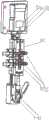
图1是本实用新型的结构示意图一;Fig. 1 is the structural representation one of the present utility model;
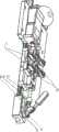
图2是本实用新型的结构示意图二;Fig. 2 is the structural representation two of the present utility model;
图3是本实用新型中局部放大的结构示意图一;3 is a partially enlarged structural schematic diagram one in the present utility model;
图4是本实用新型中局部放大的结构示意图二;4 is a partially enlarged structural schematic diagram two in the present utility model;
其中,1-支撑座一,11-扳手,12-丝杆,13-轴筒,14-连接件,111-底座,2-支撑座二,21-拉力测试器,22-辅助支撑板,31-左夹具座,32-右夹具座,33-夹件,34-枢转端,35-杠杆片,36-抵压块,37-支架,5-工件,51-线缆,52-电子器件,53-引脚。Among them, 1- support seat one, 11- wrench, 12- screw rod, 13- shaft barrel, 14- connecting piece, 111- base, 2- support seat two, 21- tension tester, 22- auxiliary support plate, 31 -left clamp seat, 32-right clamp seat, 33-clamp, 34-pivot end, 35-lever piece, 36-pressing block, 37-bracket, 5-workpiece, 51-cable, 52-electronic device , 53-pin.
具体实施方式Detailed ways
现在结合附图和实施例对本实用新型作进一步详细的说明,这些附图均为简化的示意图,仅以示意方式说明本实用新型的基本结构,因此其仅显示与本实用新型有关的构成。The present utility model will now be described in further detail with reference to the accompanying drawings and embodiments. These drawings are all simplified schematic diagrams, and only illustrate the basic structure of the present utility model in a schematic manner, so only the structures related to the present utility model are shown.
如图1~图4所示,本实施例公开了一种工件拉力测试台,包括设置在安装台上的滑轨4,滑轨4的两侧分别固定设置有支撑座一1和支撑座二2,滑轨4上活动设置有一组能在滑轨4上作直线往复动作的左夹具座31和右夹具座32;支撑座一1上设置有拉力测试器21,左夹具座31与拉力测试器21连接,右夹具座32连接的丝杆12与安装在支撑座二2上的丝杆抽拉装置连接。左夹具座31和右夹具座32上均设置有收纳工件5的工件槽,工件5中的线缆嵌入左夹具座31的工件槽中,工件5中的电子器件52嵌入右夹具座32的工件槽中;且分别通过设置在左夹具座31以及右夹具座32上的夹件33夹持固定。As shown in FIG. 1 to FIG. 4 , the present embodiment discloses a workpiece tensile test bench, which includes a slide rail 4 arranged on the installation platform, and two sides of the slide rail 4 are respectively fixed with a support seat 1 and a support seat 2 2. The slide rail 4 is movably provided with a set of
本实用新型一个较佳实施例中,左夹具座31以及右夹具座32活动嵌接在滑轨4上,且左夹具座31以及右夹具座32均能在滑轨4上沿着滑轨4作直线往复动作。夹件33包括设置在左夹具座31或右夹具座32上的支架37,支架37上与杠杆夹片35上的枢转端34枢转连接,且在支架37与杠杆夹片35之间设置有复位扭簧。且杠杆夹片35的位于枢转端34两侧的其中一端设置有与工件槽中收纳的工件5抵靠的抵压块36,杠杆夹片35另一端设置有下压分离抵压块36与工件槽的施力端。In a preferred embodiment of the present invention, the
本实用新型一个较佳实施例中,丝杆抽拉装置包括安装在支撑座二2上的底座111,底座111上与扳手11的一端枢转连接,且扳手11与底座111枢转连接的一端还与连接件14的一端枢转连接,且连接件14的另一端与丝杆12的一端枢转连接,且丝杆12的另一端穿设过设置在支撑座二2上的轴筒13后与其相邻的右夹具座32连接。In a preferred embodiment of the present invention, the screw pulling device includes a base 111 installed on the support base 2 2 , the base 111 is pivotally connected to one end of the wrench 11 , and the wrench 11 is pivotally connected to one end of the base 111 It is also pivotally connected to one end of the connecting piece 14 , and the other end of the connecting piece 14 is pivotally connected to one end of the screw rod 12 , and the other end of the screw rod 12 passes through the shaft barrel 13 provided on the support base 2 2 . It is connected with its adjacent
本实用新型的原理是:The principle of the present utility model is:
如图1~图4所示,手动下压左夹具座31和右夹具座32上设置的,杠杆夹片35的施力端,使得杠杆夹片35围绕枢转端34枢转,杠杆夹片35正对工件槽上方的抵压块36与工件槽分离打开。As shown in FIG. 1 to FIG. 4 , manually press down the force-applying end of the
通过将工件5中的线缆51以及电子器件52分别嵌设入左夹具座31和右夹具座32上的工件槽中,松开左夹具座31和右夹具座32上的夹件33。通过夹件33中设置的扭簧使杠杆夹片35复位,杠杆夹片35上的抵压块36抵压住工件槽中的工件5。By inserting the cable 51 and the electronic device 52 in the workpiece 5 into the workpiece grooves on the left and
通过掰开枢转连接在支撑座1上的扳手11,扳手11带动连接件14,连接件14拉动与左夹具座32连接的丝杆12,通过丝杆12穿设在轴筒13内,使得丝杆12顺着扳手11施力的反向作直线运动。使得右夹具座32受力与左夹具座31和分离开,对工件5的线缆51以及电子器件52产生一个方向相反的拉力,而与左夹具座31连接的拉力测试器21测得拉力参数,实现拉力测试。同时滑轨4的设置以及丝杆12和丝杆抽拉装置相相互配合,使得测试拉力施加的拉力在一直线上,且丝杆12移动的距离可以进行定量设置,避免每一次测试时施加拉力的参数存在较大偏差。By breaking apart the wrench 11 pivotally connected to the support base 1, the wrench 11 drives the connecting piece 14, and the connecting piece 14 pulls the screw rod 12 connected to the
以上依据本实用新型的理想实施例为启示,通过上述的说明内容,相关人员完全可以在不偏离本项实用新型技术思想的范围内,进行多样的变更以及修改。本项实用新型的技术性范围并不局限于说明书上的内容,必须要根据权利要求范围来确定技术性范围。The above is inspired by the ideal embodiment of the present invention. Through the above description, relevant persons can make various changes and modifications without departing from the technical idea of the present invention. The technical scope of the present invention is not limited to the content in the description, and the technical scope must be determined according to the scope of the claims.
Claims (6)
Priority Applications (1)
| Application Number | Priority Date | Filing Date | Title |
|---|---|---|---|
| CN201921420729.9UCN210833954U (en) | 2019-08-29 | 2019-08-29 | Workpiece tension test board |
Applications Claiming Priority (1)
| Application Number | Priority Date | Filing Date | Title |
|---|---|---|---|
| CN201921420729.9UCN210833954U (en) | 2019-08-29 | 2019-08-29 | Workpiece tension test board |
Publications (1)
| Publication Number | Publication Date |
|---|---|
| CN210833954Utrue CN210833954U (en) | 2020-06-23 |
Family
ID=71251713
Family Applications (1)
| Application Number | Title | Priority Date | Filing Date |
|---|---|---|---|
| CN201921420729.9UExpired - Fee RelatedCN210833954U (en) | 2019-08-29 | 2019-08-29 | Workpiece tension test board |
Country Status (1)
| Country | Link |
|---|---|
| CN (1) | CN210833954U (en) |
Cited By (1)
| Publication number | Priority date | Publication date | Assignee | Title |
|---|---|---|---|---|
| CN110487463A (en)* | 2019-08-29 | 2019-11-22 | 苏州工业职业技术学院 | A kind of workpiece force testing table |
- 2019
- 2019-08-29CNCN201921420729.9Upatent/CN210833954U/ennot_activeExpired - Fee Related
Cited By (1)
| Publication number | Priority date | Publication date | Assignee | Title |
|---|---|---|---|---|
| CN110487463A (en)* | 2019-08-29 | 2019-11-22 | 苏州工业职业技术学院 | A kind of workpiece force testing table |
Similar Documents
| Publication | Publication Date | Title |
|---|---|---|
| CN204065332U (en) | A kind of pressure resistant test tool | |
| CN102928288B (en) | A kind of tensile test fixture | |
| CN220751838U (en) | Wire harness terminal tensile force testing machine | |
| CN210833954U (en) | Workpiece tension test board | |
| CN201960301U (en) | Fast compactor | |
| CN209911114U (en) | Young modulus detection device of cable | |
| CN207556981U (en) | For the stretching clamp of low-dimensional sized materials | |
| CN115165561A (en) | A device for testing multi-directional tension, compression and bending loads | |
| CN220473199U (en) | Bolt stretching clamp | |
| CN118130227A (en) | A forming limit specimen biaxial cyclic loading fixture and test method | |
| CN110487463A (en) | A kind of workpiece force testing table | |
| CN217765820U (en) | Environment-friendly building material check out test set | |
| CN214150143U (en) | Friction testing machine | |
| CN110926738A (en) | A Fatigue Test Device for Engineering Mechanics | |
| CN212526662U (en) | Clamp for laser welding of bus bar sheet | |
| CN215767969U (en) | Fixing device for centering and adjusting distance of steel fiber tensioning and clamping jig | |
| CN210982611U (en) | Q value detection device of magnetic bar coil | |
| CN222364860U (en) | A kind of detection fixture | |
| CN223295774U (en) | High-efficient copper line toughness check out test set | |
| CN206311319U (en) | A kind of piece fixture | |
| CN223192736U (en) | A sheet material durability test module | |
| CN110412358A (en) | Q value detection device of magnetic bar coil | |
| CN108548739A (en) | A kind of quick buckling test machine of electric wire | |
| CN217765815U (en) | Clamp for testing horizontal tensile strength of sandwich structure | |
| CN219216685U (en) | A rotor core feeding device |
Legal Events
| Date | Code | Title | Description |
|---|---|---|---|
| GR01 | Patent grant | ||
| GR01 | Patent grant | ||
| CF01 | Termination of patent right due to non-payment of annual fee | Granted publication date:20200623 Termination date:20200829 | |
| CF01 | Termination of patent right due to non-payment of annual fee |