CN210812033U - Tourniquet walking separator - Google Patents
Tourniquet walking separatorDownload PDFInfo
- Publication number
- CN210812033U CN210812033UCN201920483931.XUCN201920483931UCN210812033UCN 210812033 UCN210812033 UCN 210812033UCN 201920483931 UCN201920483931 UCN 201920483931UCN 210812033 UCN210812033 UCN 210812033U
- Authority
- CN
- China
- Prior art keywords
- tourniquet
- protrusion
- detector
- box
- separation
- Prior art date
- Legal status (The legal status is an assumption and is not a legal conclusion. Google has not performed a legal analysis and makes no representation as to the accuracy of the status listed.)
- Expired - Fee Related
Links
- 238000000926separation methodMethods0.000claimsabstractdescription56
- 230000007246mechanismEffects0.000claimsabstractdescription45
- 230000007723transport mechanismEffects0.000claimsdescription9
- 238000000034methodMethods0.000description9
- 238000010586diagramMethods0.000description3
- 238000000605extractionMethods0.000description3
- 241000894006BacteriaSpecies0.000description1
- 206010011409Cross infectionDiseases0.000description1
- 206010029803Nosocomial infectionDiseases0.000description1
- 230000007547defectEffects0.000description1
- 238000005516engineering processMethods0.000description1
- 230000003203everyday effectEffects0.000description1
- 230000023597hemostasisEffects0.000description1
- 238000004806packaging method and processMethods0.000description1
- 230000000630rising effectEffects0.000description1
Images


Classifications
- A—HUMAN NECESSITIES
- A61—MEDICAL OR VETERINARY SCIENCE; HYGIENE
- A61F—FILTERS IMPLANTABLE INTO BLOOD VESSELS; PROSTHESES; DEVICES PROVIDING PATENCY TO, OR PREVENTING COLLAPSING OF, TUBULAR STRUCTURES OF THE BODY, e.g. STENTS; ORTHOPAEDIC, NURSING OR CONTRACEPTIVE DEVICES; FOMENTATION; TREATMENT OR PROTECTION OF EYES OR EARS; BANDAGES, DRESSINGS OR ABSORBENT PADS; FIRST-AID KITS
- A61F15/00—Auxiliary appliances for wound dressings; Dispensing containers for dressings or bandages
- A61F15/001—Packages or dispensers for bandages, cotton balls, drapes, dressings, gauze, gowns, sheets, sponges, swabsticks or towels
- A61F15/002—Packages or dispensers for bandages, cotton balls, drapes, dressings, gauze, gowns, sheets, sponges, swabsticks or towels dispensers for web or tape like bandages
- A—HUMAN NECESSITIES
- A61—MEDICAL OR VETERINARY SCIENCE; HYGIENE
- A61F—FILTERS IMPLANTABLE INTO BLOOD VESSELS; PROSTHESES; DEVICES PROVIDING PATENCY TO, OR PREVENTING COLLAPSING OF, TUBULAR STRUCTURES OF THE BODY, e.g. STENTS; ORTHOPAEDIC, NURSING OR CONTRACEPTIVE DEVICES; FOMENTATION; TREATMENT OR PROTECTION OF EYES OR EARS; BANDAGES, DRESSINGS OR ABSORBENT PADS; FIRST-AID KITS
- A61F15/00—Auxiliary appliances for wound dressings; Dispensing containers for dressings or bandages
- A61F15/005—Bandage applicators
- A—HUMAN NECESSITIES
- A61—MEDICAL OR VETERINARY SCIENCE; HYGIENE
- A61F—FILTERS IMPLANTABLE INTO BLOOD VESSELS; PROSTHESES; DEVICES PROVIDING PATENCY TO, OR PREVENTING COLLAPSING OF, TUBULAR STRUCTURES OF THE BODY, e.g. STENTS; ORTHOPAEDIC, NURSING OR CONTRACEPTIVE DEVICES; FOMENTATION; TREATMENT OR PROTECTION OF EYES OR EARS; BANDAGES, DRESSINGS OR ABSORBENT PADS; FIRST-AID KITS
- A61F15/00—Auxiliary appliances for wound dressings; Dispensing containers for dressings or bandages
- A61F15/02—Devices for cutting bandages of any kind, e.g. shears, cast-cutting saws
Landscapes
- Health & Medical Sciences (AREA)
- Epidemiology (AREA)
- Engineering & Computer Science (AREA)
- Biomedical Technology (AREA)
- Heart & Thoracic Surgery (AREA)
- Vascular Medicine (AREA)
- Life Sciences & Earth Sciences (AREA)
- Animal Behavior & Ethology (AREA)
- General Health & Medical Sciences (AREA)
- Public Health (AREA)
- Veterinary Medicine (AREA)
- Surgical Instruments (AREA)
Abstract
Translated fromChinese
Description
Translated fromChinese技术领域technical field
本实用新型涉及止血带分离装置,尤其止血带可以自行行走和手动分离的机构。The utility model relates to a tourniquet separation device, in particular to a mechanism by which the tourniquet can travel by itself and be manually separated.
背景技术Background technique
现有技术的止血带卷在使用过程中需要分离时,需要通过人眼来判断需要分离的长度,并采用扯拽或剪刀等设备实施最后的分离。使得止血带分离过程中,止血带分离长度确定不准而且费事费工。When the tourniquet roll of the prior art needs to be separated during use, it is necessary to judge the length to be separated by human eyes, and implement the final separation by means of pulling or scissors. Therefore, during the tourniquet separation process, the length of the tourniquet separation is inaccurate and labor-intensive.
其次,在每一次止血带分离过程时,需要先将止血带从止血带卷或止血带盒中抽取一定的长度,由于止血带使用多为医护工作者,每日反复大量地抽取的动作,增加了使用者劳动强度。Secondly, in each tourniquet separation process, it is necessary to extract a certain length of tourniquet from the tourniquet roll or tourniquet box. Since tourniquets are mostly used by medical workers, the action of repeated large-scale extraction every day increases. the labor intensity of the user.
或者现有的压脉带即使已使用了电能(电机)分切设备,但也存在以下缺陷:Or the existing pressure pulse belt has the following defects even though the electric energy (motor) slitting equipment has been used:
1)其在使用时,当设备内压脉带用完后,在更换压脉带过程中需要将整台设备(行走分离装置)拆开才能更换压脉带,造成更换不便和压脉带的交叉感染。1) When it is in use, when the pressure pulse belt in the equipment is used up, in the process of replacing the pressure pulse belt, the whole equipment (walking separation device) needs to be disassembled before the pressure pulse belt can be replaced, which causes inconvenience of replacement and inconvenience of the pressure pulse belt. cross infection.
2)当采用分切机(现有技术)止血带分切后会自动掉落至工作台致使止血带造成污染。2) When a slitting machine (existing technology) is used, the tourniquet will automatically fall to the worktable after being cut, causing the tourniquet to cause pollution.
3)拿取掉落至工作台的止血带时需目光关注降低工作效率,增加工作强度。3) When taking the tourniquet dropped to the workbench, you need to pay attention to reduce work efficiency and increase work intensity.
4)当有些时点或使用场景无法提供电源时,采用电能(电机)分切的止血带设备就无法使用。4) When the power supply cannot be provided at some time points or usage scenarios, the tourniquet equipment cut by electric energy (motor) cannot be used.
因而,提供一种能便于止血带盒更换,可无电源时使用,能降低使用者的劳动强度,卫生安全、便捷、快速分离,且可准确简便的确定止血带条的长度的止血带装置就成了业界亟待解决的技术难题。Therefore, to provide a tourniquet device that can facilitate the replacement of the tourniquet box, can be used without power supply, can reduce the labor intensity of the user, is hygienic, safe, convenient, quick to separate, and can accurately and simply determine the length of the tourniquet strip. It has become a technical problem that the industry needs to solve urgently.
实用新型内容Utility model content
提供了一种能便于止血带盒更换,可无电源时使用,能降低使用者的劳动强度,卫生安全、便捷、快速分离,且可准确简便的确定止血带条的长度的止血带装置本实用新型的发明目的是这样实现的:Provided is a tourniquet device that can facilitate the replacement of the tourniquet box, can be used without power supply, can reduce the labor intensity of the user, is hygienic, safe, convenient, quick to separate, and can accurately and simply determine the length of the tourniquet strip. The purpose of the new invention is achieved as follows:
一种止血带行走分离装置,包括止血带盒组件和止血带分离机构;所述止血带盒组件包括止血带盒和止血带,所述止血带盒上设有开口,所述止血带置于所述止血带盒内,所述止血带的一端从所述开口穿出;所述止血带上设有切线或孔,或同时设有切线和孔,止血带盒组件与止血带分离机构分别独立设置,所述止血带盒组件位于止血带分离机构的外部,所述止血带分离机构中的走带部分用于将所述止血带盒开口处穿出的所述止血带传送至所述止血带分离机构分离处;所述止血带分离机构分离处设有凸起,所述凸起用于和所述止血带上的所述切线或孔配合,配合后凸起位于孔或切线中,用于辅助所述止血带的手动断裂。A tourniquet walking separation device includes a tourniquet box assembly and a tourniquet separation mechanism; the tourniquet box assembly includes a tourniquet box and a tourniquet, the tourniquet box is provided with an opening, and the tourniquet is placed on the In the tourniquet box, one end of the tourniquet is pierced through the opening; the tourniquet is provided with a tangent or a hole, or a tangent and a hole at the same time, and the tourniquet box assembly and the tourniquet separation mechanism are respectively set independently , the tourniquet box assembly is located outside the tourniquet separation mechanism, and the belt running part in the tourniquet separation mechanism is used to transfer the tourniquet pierced through the opening of the tourniquet box to the tourniquet separation mechanism Mechanism separation; the tourniquet separation mechanism is provided with a protrusion, the protrusion is used to cooperate with the tangent line or hole on the tourniquet, and the protrusion is located in the hole or tangent line after matching, which is used to assist Manual rupture of the tourniquet described.
所述止血带上可以是间隔设有断裂线和孔,在所述止血带前进方向,每条所述预设断裂线的后方邻近所述预设断裂线处均配有所述孔。The tourniquet may be provided with break lines and holes at intervals, and in the advancing direction of the tourniquet, the holes are provided at the rear of each preset break line adjacent to the preset break line.
上述方案中,所述走带机构包括电机及压轮,所述止血带置于上下设置的所述压轮之间,所述电机带动所述压轮转动从而带动所述止血带行走。In the above solution, the belt travel mechanism includes a motor and a pressure roller, the tourniquet is placed between the pressure rollers arranged up and down, and the motor drives the pressure roller to rotate, thereby driving the tourniquet to travel.
上述方案中,还包括探测器甲,所述探测器甲用于探测在所述止血带行进方向上所述凸起的前方是否有所述止血带,所述探测器甲将探测到信息反馈给处理器,所述处理器根据接受的信息控制所述电机转动、停止或等待。In the above solution, a detector A is also included, and the detector A is used to detect whether there is the tourniquet in front of the protrusion in the traveling direction of the tourniquet, and the detector A feeds back the detected information to the tourniquet. The processor controls the motor to rotate, stop or wait according to the received information.
上述方案中止血带盒还可配有和止血带盒一起使用的固定底座,使用时止血带盒可拆卸的固定于固定底座中,固定底座与工作台固定,当止血带盒中止血带用完时从固定底座中取出换如新的即可。In the above scheme, the tourniquet box can also be equipped with a fixed base for use with the tourniquet box. When in use, the tourniquet box can be detachably fixed in the fixed base, and the fixed base is fixed with the workbench. When the tourniquet in the tourniquet box is used up Take it out of the fixed base and replace it with a new one.
进一步地,还包括探测器乙,所述探测器乙位于凸起的上方,所述探测器乙用于检测所述止血带的所述孔是否位于所述凸起的上方,并将检测到的信息发送给处理器,再由处理器控制电机的转动,从而带动所述止血带的行走和停止。其中,所述探测器乙检测的所述止血带的所述孔是否位于所述凸起的上方指:所述孔是否位于所述凸起的正上方;或所述孔是否位于所述凸起的后上方;或所述孔是否位于所述凸起的后上方至所述孔是否位于所述凸起的正上方之间的任何位置等等。Further, it also includes a detector B, the detector B is located above the bulge, the detector B is used to detect whether the hole of the tourniquet is located above the bulge, and the detected The information is sent to the processor, and the processor controls the rotation of the motor, thereby driving the tourniquet to walk and stop. Wherein, whether the hole of the tourniquet detected by the detector B is located above the protrusion refers to: whether the hole is located directly above the protrusion; or whether the hole is located on the protrusion or any position between whether the hole is located above the rear of the protrusion to whether the hole is located directly above the protrusion, etc.
上述方案中,还包括探测器丙,所述探测器丙位于所述止血带盒与所述走带机构之间,所述探测器丙用于检测是否更换了新的所述止血带盒组件,并将检测到的信息发送给处理器,所述处理器根据收集到的反馈信息控制所述电机运行或停止。当探测器丙探测到所述止血带盒与所述走带机构之间没有止血带时,说明需要更换止血带盒,此时处理器控制所述电机停止转动,当探测器丙探测到所述止血带盒与所述走带机构之间有止血带后,所述处理器重启电机或控制电机开始转动。In the above solution, a detector C is also included, and the detector C is located between the tourniquet case and the belt travel mechanism, and the detector C is used to detect whether the tourniquet case assembly is replaced with a new one, The detected information is sent to the processor, and the processor controls the motor to run or stop according to the collected feedback information. When the detector C detects that there is no tourniquet between the tourniquet box and the transport mechanism, it means that the tourniquet box needs to be replaced, and the processor controls the motor to stop rotating. After there is a tourniquet between the tourniquet box and the belt transport mechanism, the processor restarts the motor or controls the motor to start rotating.
上述方案中,所述止血带分离机构还包括支撑结构;所述支撑结构用于支撑所述走带机构传送的所述止血带;所述凸起用于与经过所述支撑结构传送的所述止血带的所述孔配合定位并用于辅助所述止血带的手动断裂。In the above solution, the tourniquet separation mechanism further includes a support structure; the support structure is used to support the tourniquet transmitted by the belt transport mechanism; the protrusion is used to communicate with the tourniquet transmitted through the support structure. The holes of the band are co-located and used to assist in manual breaking of the tourniquet.
上述方案中,所述支撑结构包括止血带抬升结构,所述止血带抬升结构用于将行进中的所述止血带向上抬起,使在所述止血带行进至所述凸起时,所述止血带的下平面不低于凸起的上端面。所述止血带抬升结构可以是凸台、或自止血带行进方向抬升的斜面、或弹片等。In the above solution, the support structure includes a tourniquet lifting structure, and the tourniquet lifting structure is used to lift the traveling tourniquet upward, so that when the tourniquet travels to the bulge, the The lower plane of the tourniquet is not lower than the upper end surface of the protrusion. The tourniquet lifting structure may be a boss, an inclined plane that is lifted from the traveling direction of the tourniquet, or a shrapnel or the like.
当所述止血带抬升结构为弹片时,所述弹片位于止血带行进方向的所述凸起的后方,所述止血带的下方,所述弹片用于将行进中的止血带向上抬起,使在止血带前进方向上位于凸起后侧的止血带的下平面不低于凸起的上端面,且当所述止血带上的所述孔与所述凸起配合时,所述弹片产生形变。When the tourniquet lifting structure is an elastic piece, the elastic piece is located behind the protrusion in the traveling direction of the tourniquet, and below the tourniquet, the elastic piece is used to lift the traveling tourniquet upward, so that the The lower plane of the tourniquet located on the rear side of the protrusion in the traveling direction of the tourniquet is not lower than the upper end surface of the protrusion, and when the hole on the tourniquet is matched with the protrusion, the elastic piece is deformed .
上述方案中,位于所述止血带行进方向,所述止血带分离机构前部的下方设有止血带的接盘,所述接盘用于承接止血带,避免所述止血带被污染。In the above solution, in the traveling direction of the tourniquet, a tourniquet adapter is provided below the front of the tourniquet separation mechanism, and the adapter is used to receive the tourniquet to prevent the tourniquet from being polluted.
上述方案中,位于止血带行进方向的所述走带机构的后方,设有止血带导向结构。所述止血带导向结构可以是在所述止血带行进方向和/或所述止血带的宽度方向设有限位结构,如U型托盘等等,但不限于此。In the above solution, a tourniquet guide structure is provided at the rear of the travel mechanism in the traveling direction of the tourniquet. The tourniquet guiding structure may be provided with a limiting structure in the traveling direction of the tourniquet and/or the width direction of the tourniquet, such as a U-shaped tray, etc., but is not limited thereto.
本实用新型的优点在于:The advantages of the present utility model are:
1、本实用新型无需手动抽取止血带(压脉带)便于操作,降低了劳动强度。1. The present utility model does not need to manually extract the tourniquet (pressor belt), which is convenient for operation and reduces labor intensity.
2、本实用新型因止血带盒与止血带行走机构止血带分离机构独立设置,所以当止血带用完需要更换时,仅需更换止血带带盒,更换更加便捷。2. The tourniquet box and the tourniquet separation mechanism of the tourniquet traveling mechanism of the present invention are independently set, so when the tourniquet is used up and needs to be replaced, only the tourniquet box needs to be replaced, and the replacement is more convenient.
3、本实用新型在更换止血带时,止血带行走机构分离机构独立设置于止血带盒外,在更换止血带的过程中,止血带行走机构止血带分离机构处于相对封闭的环境,确保止血带不会被外部细菌感染,故而更加卫生。3. When the tourniquet is replaced in the present invention, the tourniquet traveling mechanism separation mechanism is independently set outside the tourniquet box. During the tourniquet replacement process, the tourniquet traveling mechanism tourniquet separation mechanism is in a relatively closed environment to ensure the tourniquet. It is more hygienic because it is not infected by external bacteria.
4、本实用新型止血带均有独立的包装盒,止血带用完后,只需跟换新的止血带盒即可,同时在止血带的使用过程和更换过程中止血带都被置于密封的止血带盒内,所以较现有技术中更换止血带的过程中止血带暴露于空气中带而言,故而止血带更加卫生、无污染。4. The tourniquet of the present invention has an independent packaging box. After the tourniquet is used up, it is only necessary to replace it with a new tourniquet box. At the same time, the tourniquet is placed in a sealed place during the use and replacement of the tourniquet. Therefore, the tourniquet is more hygienic and pollution-free than the tourniquet exposed to the air in the process of replacing the tourniquet in the prior art.
5)止血带分离后不会掉落至工作台致使止血带污染。5) After the tourniquet is separated, it will not fall to the workbench to cause the tourniquet to be polluted.
6)止血带分离后无需目光关注再次拿取,减少使用步骤,提高效率。6) After the tourniquet is separated, there is no need to pay attention to taking it again, reducing the use steps and improving the efficiency.
7)可以在无电源时使用,直接采用手动抽取、分离。7) It can be used when there is no power supply, and it can be directly extracted and separated manually.
现有的止血带盒,使用者在每次抽取止血带时,需要先将止血带抽取至所述凸起,是所述孔和所述凸起配合,然后再将止血带从所述预设断裂线处分离开。本实用新型免去了使用者抽取过程的抽取动作,一方面节省了时间,另一方面降低了使用者的工作强度。In the existing tourniquet box, each time the user draws the tourniquet, he needs to extract the tourniquet to the bulge first, and the hole is matched with the bulge, and then the tourniquet is removed from the preset. Separate at the break line. The utility model eliminates the extraction action of the user in the extraction process, which saves time on the one hand, and reduces the work intensity of the user on the other hand.
附图说明Description of drawings
图1为本实用新型结构示意图。Figure 1 is a schematic structural diagram of the utility model.
图2本实用新型一实施例止血带结构示意图。FIG. 2 is a schematic structural diagram of a tourniquet according to an embodiment of the present invention.
图3为本实用新型一实施例止血带分离机构结构示意图。3 is a schematic structural diagram of a tourniquet separation mechanism according to an embodiment of the present invention.
图4为本实用新型一实施例止血带分离机构孔与凸起配合过程示意图-1。FIG. 4 is a schematic diagram-1 of the matching process between the hole and the protrusion of the tourniquet separation mechanism according to an embodiment of the present invention.
图5为本实用新型一实施例止血带分离机构孔与凸起配合过程示意图-2。FIG. 5 is a schematic diagram-2 of the matching process between the hole and the protrusion of the tourniquet separation mechanism according to an embodiment of the present invention.
图6为本实用新型一实施例止血带分离机构孔与凸起配合过程示意图-3。FIG. 6 is a schematic diagram-3 of the matching process between the hole and the protrusion of the tourniquet separation mechanism according to an embodiment of the present invention.
图7为本实用新型一实施例止血带分离机构孔与凸起配合过程示意图-4。FIG. 7 is a schematic diagram-4 of the matching process between the hole and the protrusion of the tourniquet separation mechanism according to an embodiment of the present invention.
图8为本实用新型一实施例止血带分离机构预设断裂线与凸起配合过程示意图-1。FIG. 8 is a schematic diagram-1 of the matching process between the preset breaking line and the protrusion of the tourniquet separation mechanism according to an embodiment of the present invention.
图9为本实用新型一实施例止血带分离机构和止血带盒配合使用的固定底座示意图-1。9 is a schematic diagram-1 of a fixed base used in conjunction with a tourniquet separation mechanism and a tourniquet box according to an embodiment of the present invention.
图中:In the picture:
1止血带盒组件,11止血带盒,111开口,1 tourniquet case assembly, 11 tourniquet case, 111 opening,
12止血带,121孔,122预设断裂线,125贯通切口,123止血带的下平面,124 孔第一边,12 Tourniquet, 121 Hole, 122 Preset Break Line, 125 Through Cut, 123 Lower Plane of Tourniquet, 124 Hole First Side,
2走带机构,21压轮,22压轮,23固定底座2 transport mechanism, 21 pressure roller, 22 pressure roller, 23 fixed base
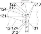
3止血带分离机构,31凸起,311上端面,312后侧面,313前侧面,3 Tourniquet separation mechanism, 31 convex, 311 upper end face, 312 rear side, 313 front side,
32支撑结构,33止血带抬升结构,32 support structure, 33 tourniquet lift structure,
41探测器甲,42探测器乙,43探测器丙,41 Detector A, 42 Detector B, 43 Detector C,
5接盘,5 pick up,
D1孔第一边至后侧面的距离,D2孔第一边至前侧面的距离。The distance from the first side of the D1 hole to the rear side, and the distance from the first side of the D2 hole to the front side.
具体实施方式Detailed ways
下面结合附图对本实用新型做进一步的说明,以下实施例仅为优选例,并不是对本实用新型的范围加以限制,相反地,其目的是希望能涵盖各种改变及具相等性的安排于本实用新型所欲申请之专利范围的范畴内。The present utility model will be further described below in conjunction with the accompanying drawings. The following embodiments are only preferred examples and are not intended to limit the scope of the present utility model. On the contrary, the purpose is to cover various changes and equivalent arrangements in the present utility model. The utility model is within the scope of the patent scope to be applied for.
实施例:下面结合图1至图8对本实用新型做进一步的说明:Embodiment: The utility model is further described below in conjunction with Fig. 1 to Fig. 8:
一种止血带行走分离装置,包括止血带盒组件1、止血带分离机构3和走带机构2、探测器甲41、探测器乙42、探测器43、处理器、接盘5.A tourniquet walking separation device, comprising a tourniquet box assembly 1, a tourniquet separation mechanism 3 and a
止血带盒组件1包括止血带盒11和止血带12。止血带盒11上设有开口111,止血带12置于止血带盒11内,止血带12的一端从开口111穿出。止血带12上间隔设有预设断裂线122和孔121。在止血带前进方向,每条预设断裂线122的后方邻近预设断裂线处122均配有孔121。The tourniquet case assembly 1 includes a
走带机构2包括电机(图中未标出)及压轮(21、22),止血带12置于上下设置的压轮(21、22)之间,电机带动压轮(21、22)转动从而带动止血带 12行走。The
止血带分离机构3包括支撑结构32和凸起31;支撑结构32为止血带抬升结构33,具体为一个沿止血带行走方向上升的斜面,止血带抬升结构33用于支撑走带机构2传送的止血带12。止血带抬升结构33用于将行进中的止血带12 向上抬起,使在止血带12行进至凸起31时,止血带的下平面123不低于凸起 31的上端面311。凸起31用于与经过止血带抬升结构33传送的止血带12的孔121配合定位,或凸起31用于与经过止血带抬升结构33传送的预设断裂线122 贯通切口125处配合定位并用于辅助所述止血带的手动断裂。The tourniquet separation mechanism 3 includes a
止血带行进方向上凸起31前部设有探测器甲41,探测器甲41用于检测凸起31的前方是否有止血带12,当探测器甲41探测到凸起31的前方有一个止血带单元(两个预设断裂线122之间的止血带12为一个止血带单元)时,探测器甲41将相关信息反馈给处理器(图中未标出),处理器根据接受的信息控制电机(图中未标出)停止转动。当探测器甲41探测到凸起31的前方没有止血带时,探测器甲41将相关信息反馈给处理器(图中未标出),处理器根据接受的信息控制电机转动,并带动止血带向前行进一个止血带单元。A
凸起31的上方设有探测器乙42,探测器乙42用于检测的止血带12的孔 121是否位于凸起31的上方,并将检测到的信息发送给处理器。即当检测到孔第一边至后侧面的距离D1和/或孔第一边至前侧面的距离D2符合预设的条件时,探测器乙42将检测到信息发送给处理器,由处理器控制电机的停止运行,从而止血带12停止行进。当检测到孔第一边至后侧面的距离D1和/或孔第一边至前侧面的距离D2不符合预设的条件时,探测器乙42将检测到信息发送给处理器,处理器控制电机的运行,由电机转动带动压轮(21、22)转动,从而带动止血带 12继续前行,直至孔第一边至后侧面的距离D1和/或孔第一边至前侧面的距离 D2符合预设的条件,电机停止转动。A
探测器丙43位于止血带盒11与走带机构之间2,当止血带盒组件1中止血带12用完后,探测器43检测到止血带盒11与走带机构之间2没有止血带12 时,探测器43将检测到的信息发送给处理器,处理器控制电机停止转动。待更换了新的止血带盒组件1后,探测器43检测到止血带盒11与走带机构之间2有止血带12后,探测器43将检测到的信息发送给处理器,处理器控制电机开始转动,有电机带动压轮(21、22)转动,从而带动止血带12向前行进。The
止血带分离机构3前部的下方设有止血带的接盘5,接盘5用于承接止血带12,避免止血带12被污染。A
Claims (10)
Translated fromChineseApplications Claiming Priority (4)
| Application Number | Priority Date | Filing Date | Title |
|---|---|---|---|
| CN2018205230215 | 2018-04-12 | ||
| CN201820523021 | 2018-04-12 | ||
| CN201821408838 | 2018-08-29 | ||
| CN2018214088384 | 2018-08-29 |
Publications (1)
| Publication Number | Publication Date |
|---|---|
| CN210812033Utrue CN210812033U (en) | 2020-06-23 |
Family
ID=68248494
Family Applications (2)
| Application Number | Title | Priority Date | Filing Date |
|---|---|---|---|
| CN201920483931.XUExpired - Fee RelatedCN210812033U (en) | 2018-04-12 | 2019-04-11 | Tourniquet walking separator |
| CN201910288209.5APendingCN110368197A (en) | 2018-04-12 | 2019-04-11 | A kind of tourniquet walking separator |
Family Applications After (1)
| Application Number | Title | Priority Date | Filing Date |
|---|---|---|---|
| CN201910288209.5APendingCN110368197A (en) | 2018-04-12 | 2019-04-11 | A kind of tourniquet walking separator |
Country Status (1)
| Country | Link |
|---|---|
| CN (2) | CN210812033U (en) |
Cited By (1)
| Publication number | Priority date | Publication date | Assignee | Title |
|---|---|---|---|---|
| CN110368197A (en)* | 2018-04-12 | 2019-10-25 | 无锡市凯顺医疗器械制造有限公司 | A kind of tourniquet walking separator |
Family Cites Families (15)
| Publication number | Priority date | Publication date | Assignee | Title |
|---|---|---|---|---|
| GB2485572A (en)* | 2010-11-19 | 2012-05-23 | Shakeel Islam | Dispensing apparatus for a reel of disposable tourniquets |
| CN202191330U (en)* | 2011-02-23 | 2012-04-18 | 史维伟 | Disposable tourniquet with continuous drawing type bayonet |
| CN203411144U (en)* | 2013-07-01 | 2014-01-29 | 杨迪 | Tourniquet package box |
| CN203815528U (en)* | 2014-01-22 | 2014-09-10 | 无锡市凯顺医疗器械制造有限公司 | Continuous drawing device for tourniquet |
| CN203828997U (en)* | 2014-01-22 | 2014-09-17 | 无锡市凯顺医疗器械制造有限公司 | Tourniquet and continuous extraction device with same |
| CN104783859B (en)* | 2014-01-22 | 2017-10-13 | 无锡市凯顺医疗器械制造有限公司 | The fit structure of automatic identification arm-rest belt preset length and preset length recognition methods |
| CN203815527U (en)* | 2014-01-22 | 2014-09-10 | 无锡市凯顺医疗器械制造有限公司 | Tourniquet with positioning and fracturing function holes |
| CN204049740U (en)* | 2014-06-24 | 2014-12-31 | 天津海迈医用科技有限公司 | A kind of have the tourniquet receiver automatically cutting band function |
| CN205126337U (en)* | 2015-10-09 | 2016-04-06 | 杭州市西湖区古荡街道社区卫生服务中心 | Press arteries and veins area and take out tight device in succession automatically |
| CN105708555B (en)* | 2016-04-14 | 2018-05-08 | 天津海迈医用科技有限公司 | A kind of automatic tourniquet machine for spitting band |
| CN106109155B (en)* | 2016-07-29 | 2017-07-28 | 郑中富 | One kind blood sampling workbench tourniquet laying apparatus |
| CN107582126A (en)* | 2017-08-07 | 2018-01-16 | 无锡市第五人民医院 | A kind of full-automatic arm-rest belt feeding mechanism |
| CN210812033U (en)* | 2018-04-12 | 2020-06-23 | 无锡市凯顺医疗器械制造有限公司 | Tourniquet walking separator |
| CN108720881A (en)* | 2018-05-21 | 2018-11-02 | 天津海迈医用科技有限公司 | A kind of tourniquet that can spit band automatically spits band machine |
| CN108720882B (en)* | 2018-05-21 | 2020-03-27 | 天津海迈医用科技有限公司 | Medical tourniquet machine capable of automatically cutting and discharging tourniquet |
- 2019
- 2019-04-11CNCN201920483931.XUpatent/CN210812033U/ennot_activeExpired - Fee Related
- 2019-04-11CNCN201910288209.5Apatent/CN110368197A/enactivePending
Cited By (1)
| Publication number | Priority date | Publication date | Assignee | Title |
|---|---|---|---|---|
| CN110368197A (en)* | 2018-04-12 | 2019-10-25 | 无锡市凯顺医疗器械制造有限公司 | A kind of tourniquet walking separator |
Also Published As
| Publication number | Publication date |
|---|---|
| CN110368197A (en) | 2019-10-25 |
Similar Documents
| Publication | Publication Date | Title |
|---|---|---|
| CN104037445B (en) | Automatic battery wrapping film machine | |
| CN210812033U (en) | Tourniquet walking separator | |
| CN203254479U (en) | Thin film automatic cutting device | |
| CN212885455U (en) | Battery disassembly device | |
| CN209956321U (en) | A kind of soft-pack lithium battery aluminum-plastic film unwinding and piercing mechanism | |
| CN206426150U (en) | Integration apparatus is collected in a kind of rubber strip cutting | |
| CN206156278U (en) | Machine is applied in condenser subsides | |
| CN202239868U (en) | Cutting machine for battery pole plate | |
| CN205735218U (en) | A kind of cardboard cutter | |
| CN219237648U (en) | An automatic peeling and recycling mechanism for the outer packaging of sampling swabs | |
| CN204760474U (en) | Pole piece pulls and waste material processing system in step | |
| CN204868966U (en) | Automatic conveyor that cuts of sleeve pipe | |
| CN204662149U (en) | Cloth cutting device | |
| CN203739321U (en) | Plastic shopping bag hand lifting hole and easily-torn mark integrated machining device | |
| CN206393706U (en) | A kind of automatic gas cutting machine | |
| CN210785031U (en) | A kind of pressure pulse belt walking separation mechanism | |
| CN215395508U (en) | Cutting device from small-size sample of type paper | |
| CN209226055U (en) | A paper feeding device for a die-cutting machine | |
| CN105048360B (en) | Cable cutting mechanism and working method thereof | |
| CN210703867U (en) | Piece collection device in new forms of energy electricity core pole piece production process | |
| CN209177667U (en) | A kind of wound roll material automatic collecting mechanism | |
| CN109742040B (en) | Mucous membrane machine and mucous membrane method | |
| CN202687620U (en) | Semiautomatic label removing machine | |
| CN206486086U (en) | A kind of label profile cutting means | |
| CN109440285B (en) | Sweater tablet disassembling machine |
Legal Events
| Date | Code | Title | Description |
|---|---|---|---|
| GR01 | Patent grant | ||
| GR01 | Patent grant | ||
| CF01 | Termination of patent right due to non-payment of annual fee | ||
| CF01 | Termination of patent right due to non-payment of annual fee | Granted publication date:20200623 |