CN210768294U - Novel hinge and mechanical equipment - Google Patents
Novel hinge and mechanical equipmentDownload PDFInfo
- Publication number
- CN210768294U CN210768294UCN201921467514.2UCN201921467514UCN210768294UCN 210768294 UCN210768294 UCN 210768294UCN 201921467514 UCN201921467514 UCN 201921467514UCN 210768294 UCN210768294 UCN 210768294U
- Authority
- CN
- China
- Prior art keywords
- hinge
- rotating shaft
- groove
- upper hinge
- limiting
- Prior art date
- Legal status (The legal status is an assumption and is not a legal conclusion. Google has not performed a legal analysis and makes no representation as to the accuracy of the status listed.)
- Expired - Fee Related
Links
Images


Landscapes
- Hinges (AREA)
Abstract
Translated fromChinese
Description
Translated fromChinese技术领域technical field
本实用新型涉及机械零件技术领域,具体而言,涉及一种新型铰链和机械设备。The utility model relates to the technical field of mechanical parts, in particular to a novel hinge and mechanical equipment.
背景技术Background technique
现有挖掘机门总成,工具箱等均需要用到门铰链。由于现有铰链的结构为合页加转轴,无限位结构,需要加风钩等作为限位。Existing excavator door assemblies, tool boxes, etc. all need door hinges. Since the structure of the existing hinge is a hinge plus a rotating shaft, the structure is infinite, and it is necessary to add an air hook and the like as a limit.
但是风钩限位板需直接焊接在门板上,造成了局部的焊接变形,装配不便,使门等外观件不美观。However, the air hook limit plate needs to be directly welded on the door plate, which causes local welding deformation, inconvenient assembly, and unsightly appearance parts such as doors.
实用新型内容Utility model content
本实用新型的目的包括,例如,提供了一种新型铰链和机械设备,铰链结构自身具有限位功能,不要另外焊接风钩即可实现限位功能,且装配方便,外观美观。The purpose of the present invention includes, for example, to provide a new type of hinge and mechanical equipment, the hinge structure itself has a limit function, the limit function can be achieved without additionally welding the air hook, and the assembly is convenient and the appearance is beautiful.
本实用新型的实施例可以这样实现:Embodiments of the present utility model can be implemented as follows:
第一方面,本实用新型实施例提供一种新型铰链,包括:In the first aspect, an embodiment of the present invention provides a novel hinge, including:
上合页、转动轴、限位销和下合页;Upper hinge, rotating shaft, limit pin and lower hinge;
上合页可转动地设置转动轴上,转动轴的上端设有周向方向延伸的限位槽;The upper hinge is rotatably arranged on the rotating shaft, and the upper end of the rotating shaft is provided with a limit groove extending in the circumferential direction;
限位销的一端设置在上合页上,限位销的另一端可滑动地设置限位槽内,且上合页相对转动轴转动时,限位销一直位于限位槽内;One end of the limit pin is arranged on the upper hinge, and the other end of the limit pin is slidably arranged in the limit groove, and when the upper hinge rotates relative to the rotating shaft, the limit pin is always located in the limit groove;
转动轴的下端与下合页连接。The lower end of the rotating shaft is connected with the lower hinge.
在可选的实施方式中,转动轴上还设置有连接槽;In an optional embodiment, a connecting groove is further provided on the rotating shaft;
连接槽的一端与转动轴的顶面连通,连接槽的另一端通过弯折部与限位槽的端部连通;One end of the connecting groove is communicated with the top surface of the rotating shaft, and the other end of the connecting groove is communicated with the end of the limiting groove through the bending part;
弯折部与限位槽之间具有预设夹角;There is a preset angle between the bending part and the limit groove;
且弯折部向限位槽远离转动轴顶面的方向延伸。And the bent portion extends in the direction away from the top surface of the rotating shaft in the direction of the limiting groove.
在可选的实施方式中,弯折部包括相互连通的第一段和第二段;In an optional embodiment, the bent portion includes a first segment and a second segment that communicate with each other;
连接槽沿转动轴的轴线方向延伸,连接槽远离转动轴顶面的端部依次通过第一段、第二段与限位槽连通;The connecting groove extends along the axis direction of the rotating shaft, and the end of the connecting groove away from the top surface of the rotating shaft is communicated with the limiting groove through the first section and the second section in turn;
第一段与连接槽具有预设的第一夹角;The first segment and the connecting groove have a preset first angle;
第一段与第二段具有预设的第二夹角;The first segment and the second segment have a preset second angle;
第二段与限位槽具有预设的第三夹角。The second segment and the limiting groove have a preset third angle.
在可选的实施方式中,第一夹角、第二夹角和第三夹角均为90°。In an optional embodiment, the first included angle, the second included angle and the third included angle are all 90°.
在可选的实施方式中,上合页具有贯穿的第一连接孔;In an optional embodiment, the upper hinge has a penetrating first connection hole;
上合页通过第一连接孔与转动轴的上端可转动地连接;The upper hinge is rotatably connected with the upper end of the rotating shaft through the first connecting hole;
第一连接孔的内壁设置有配合槽孔,限位销远离限位槽的端部设置在配合槽孔中。The inner wall of the first connecting hole is provided with a matching slot hole, and the end of the limit pin away from the limit slot is arranged in the matching slot hole.
在可选的实施方式中,还包括弹性件;In an optional embodiment, an elastic member is also included;
弹性件设置在转动轴上,且弹性件的一端设置在上合页上,弹性件的另一端设置在下合页上;The elastic piece is arranged on the rotating shaft, one end of the elastic piece is arranged on the upper hinge, and the other end of the elastic piece is arranged on the lower hinge;
当上合页与下合页相互靠近时,弹性件提供以使上合页和下合页相互分离的弹性力。When the upper hinge and the lower hinge approach each other, the elastic member provides elastic force to separate the upper hinge and the lower hinge from each other.
在可选的实施方式中,下合页包括相互连接的页板和配合部;In an optional embodiment, the lower hinge includes an interconnected leaf plate and a mating portion;
配合部设置在转动轴上,且配合部的外壁上设置有多个周向布置的调节凹槽,弹性件的端部设置在调节凹槽中;The matching portion is arranged on the rotating shaft, and a plurality of circumferentially arranged adjusting grooves are arranged on the outer wall of the matching portion, and the end portion of the elastic member is arranged in the adjusting groove;
弹性件的端部位于不同的调节凹槽中时,弹性件提供不同大小的以使上合页和下合页相互分离的弹性力。When the ends of the elastic pieces are located in different adjustment grooves, the elastic pieces provide different elastic forces for separating the upper hinge and the lower hinge from each other.
在可选的实施方式中,下合页具有贯穿的第二连接孔,第二连接孔的内壁设置有定位凸起;In an optional embodiment, the lower hinge has a second connecting hole passing through, and the inner wall of the second connecting hole is provided with a positioning protrusion;
转动轴的下端具有径向向内的凹陷部,凹陷部延伸至转动轴的底部;The lower end of the rotating shaft has a radially inward concave portion, and the concave portion extends to the bottom of the rotating shaft;
定位凸起与凹陷部卡接配合,以用于对下合页的周向限位。The positioning protrusion is snap-fitted with the concave portion, so as to limit the circumferential direction of the lower hinge.
在可选的实施方式中,弹性件套设在转动轴上。In an optional embodiment, the elastic member is sleeved on the rotating shaft.
第二方面,本实用新型实施例提供一种机械设备,机械设备包括前述实施方式中任一项的新型铰链。In a second aspect, an embodiment of the present invention provides a mechanical device, and the mechanical device includes the novel hinge of any one of the foregoing embodiments.
本实用新型实施例的有益效果包括,例如:The beneficial effects of the embodiments of the present invention include, for example:
新型铰链的上合页、转动轴和下合页相互连接,其中上合页与转动轴转动连接。设置在上合页上的限位销可滑动地设置限位槽内,如此通过限位销和限位槽的配合即可实现新型铰链的限位功能,不需要再设置风钩等限位结构。这样的新型铰链结构简单、自身具有限位功能,无需附加其他限位结构,且安装方便、外观美观,具有显著的经济效益。The upper hinge, the rotating shaft and the lower hinge of the new hinge are connected with each other, wherein the upper hinge and the rotating shaft are connected in rotation. The limit pin arranged on the upper hinge is slidably arranged in the limit groove, so that the limit function of the new hinge can be realized through the cooperation of the limit pin and the limit groove, and there is no need to set limit structures such as air hooks . Such a new hinge has a simple structure, has a limiting function itself, does not need to add other limiting structures, is easy to install, has a beautiful appearance, and has significant economic benefits.
附图说明Description of drawings
为了更清楚地说明本实用新型实施例的技术方案,下面将对实施例中所需要使用的附图作简单地介绍,应当理解,以下附图仅示出了本实用新型的某些实施例,因此不应被看作是对范围的限定,对于本领域普通技术人员来讲,在不付出创造性劳动的前提下,还可以根据这些附图获得其他相关的附图。In order to illustrate the technical solutions of the embodiments of the present invention more clearly, the accompanying drawings that need to be used in the embodiments will be briefly introduced below. It should be understood that the following drawings only show some embodiments of the present invention. Therefore, it should not be regarded as a limitation of the scope. For those of ordinary skill in the art, other related drawings can also be obtained from these drawings without any creative effort.
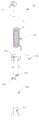
图1为本实用新型的新型铰链的结构示意图;Fig. 1 is the structural representation of the novel hinge of the present invention;
图2为本实用新型的新型铰链的装配图;Fig. 2 is the assembly drawing of the novel hinge of the present utility model;
图3为本实用新型的新型铰链的转动轴的局部示意图;Fig. 3 is the partial schematic diagram of the rotating shaft of the novel hinge of the present invention;
图4为本实用新型的新型铰链的上合页的结构示意图;Fig. 4 is the structural representation of the upper hinge of the novel hinge of the present invention;
图5为本实用新型的新型铰链的下合页的结构示意图;Fig. 5 is the structural representation of the lower hinge of the novel hinge of the present invention;
图6为本实用新型的新型铰链的转动轴的另一局部示意图。6 is another partial schematic view of the rotating shaft of the novel hinge of the present invention.
图标:10-新型铰链;100-上合页;110-第一连接孔;111-配合槽孔;200-转动轴;210-限位槽;220-连接槽;230-弯折部;231-第一段;232-第二段;240-凹陷部;300-限位销;400-下合页;410-第二连接孔;411-定位凸起;420-页板;430-配合部;431-调节凹槽;500-弹性件。Icon: 10-new hinge; 100-upper hinge; 110-first connecting hole; 111-matching slot; 200-rotating shaft; 210-limiting slot; 220-connecting slot; 230-bending part; 231- 1st segment; 232-second segment; 240-recessed part; 300-limiting pin; 400-lower hinge; 410-second connecting hole; 411-positioning protrusion; 420-leaf plate; 430-matching part; 431-adjustment groove; 500-elastic piece.
具体实施方式Detailed ways
为使本实用新型实施例的目的、技术方案和优点更加清楚,下面将结合本实用新型实施例中的附图,对本实用新型实施例中的技术方案进行清楚、完整地描述,显然,所描述的实施例是本实用新型一部分实施例,而不是全部的实施例。通常在此处附图中描述和示出的本实用新型实施例的组件可以以各种不同的配置来布置和设计。In order to make the purposes, technical solutions and advantages of the embodiments of the present utility model clearer, the technical solutions in the embodiments of the present utility model will be clearly and completely described below with reference to the accompanying drawings in the embodiments of the present utility model. The embodiments described above are a part of the embodiments of the present invention, but not all of the embodiments. The components of the embodiments of the invention generally described and illustrated in the drawings herein may be arranged and designed in a variety of different configurations.
因此,以下对在附图中提供的本实用新型的实施例的详细描述并非旨在限制要求保护的本实用新型的范围,而是仅仅表示本实用新型的选定实施例。基于本实用新型中的实施例,本领域普通技术人员在没有作出创造性劳动前提下所获得的所有其他实施例,都属于本实用新型保护的范围。Accordingly, the following detailed description of the embodiments of the invention provided in the accompanying drawings is not intended to limit the scope of the invention as claimed, but is merely representative of selected embodiments of the invention. Based on the embodiments of the present invention, all other embodiments obtained by those of ordinary skill in the art without creative work fall within the protection scope of the present invention.
应注意到:相似的标号和字母在下面的附图中表示类似项,因此,一旦某一项在一个附图中被定义,则在随后的附图中不需要对其进行进一步定义和解释。It should be noted that like numerals and letters refer to like items in the following figures, so once an item is defined in one figure, it does not require further definition and explanation in subsequent figures.
在本实用新型的描述中,需要说明的是,若出现术语“上”、“下”、“内”、“外”等指示的方位或位置关系为基于附图所示的方位或位置关系,或者是该实用新型产品使用时惯常摆放的方位或位置关系,仅是为了便于描述本实用新型和简化描述,而不是指示或暗示所指的装置或元件必须具有特定的方位、以特定的方位构造和操作,因此不能理解为对本实用新型的限制。In the description of the present utility model, it should be noted that, if the azimuth or positional relationship indicated by the terms "upper", "down", "inner", "outer", etc. appears, it is based on the azimuth or positional relationship shown in the accompanying drawings, Or the orientation or positional relationship that the utility model product is usually placed in use is only for the convenience of describing the present utility model and simplifying the description, rather than indicating or implying that the device or element referred to must have a specific orientation or a specific orientation. construction and operation, and therefore should not be construed as a limitation of the present invention.
此外,若出现术语“第一”、“第二”等仅用于区分描述,而不能理解为指示或暗示相对重要性。In addition, where the terms "first", "second" and the like appear, they are only used to differentiate the description, and should not be construed as indicating or implying relative importance.
需要说明的是,在不冲突的情况下,本实用新型的实施例中的特征可以相互结合。It should be noted that the features in the embodiments of the present invention may be combined with each other under the condition of no conflict.
请参考图1,本实施例提供了一种新型铰链10,包括上合页100、转动轴200、限位销300和下合页400。Referring to FIG. 1 , this embodiment provides a novel hinge 10 , which includes an
上合页100可转动地设置转动轴200上,转动轴200的上端设有周向方向延伸的限位槽210;The
限位销300的一端设置在上合页100上,限位销300的另一端可滑动地设置限位槽210内,且所述上合页100相对转动轴200可转动地设置转动轴200时,限位销300一直位于限位槽210内;One end of the
转动轴200的下端与下合页400连接。The lower end of the
现有挖掘机门总成,工具箱等均需要用到门铰链,由于现有铰链结构为合页加转轴,无限位结构,需要加风钩等作为限位。由于风钩限位板需直接焊接在门板上,造成了局部的焊接变形,使门等外观件不美观。加之风钩长时间使用后易变形,造成门与配重干涉,掉漆;占用门内的操作维修空间。Existing excavator door assemblies, tool boxes, etc. all need door hinges. Since the existing hinge structure is a hinge plus a rotating shaft, an infinite structure, it is necessary to add an air hook and the like as a limit. Because the air hook limit plate needs to be welded directly on the door plate, local welding deformation is caused, which makes the appearance parts such as the door unsightly. In addition, the air hook is easily deformed after long-term use, causing interference between the door and the counterweight, and paint peeling; occupying the operation and maintenance space in the door.
新型铰链10的上合页100、转动轴200和下合页400相互连接,其中上合页100与转动轴200转动连接。设置在上合页100上的限位销300可滑动地设置限位槽210内,如此通过限位销300和限位槽210的配合即可实现新型铰链10的限位功能,不需要再设置风钩等限位结构。且上合页100相对转动轴200转动时,限位销300一直位于限位槽210内;如此保障了限位功能的稳定性和可靠性。这样的新型铰链10结构简单、自身具有限位功能,无需附加其他限位结构,且安装方便、外观美观,具有显著的经济效益。The
请参照图1至图6,以了解新型铰链10的更多结构细节。Please refer to FIGS. 1 to 6 for more structural details of the new hinge 10 .
在可选的实施方式中,转动轴200上还设置有连接槽220;连接槽220的一端与转动轴200的顶面连通,连接槽220的另一端通过弯折部230与限位槽210的端部连通;弯折部230与限位槽210之间具有预设夹角;且弯折部230向限位槽210远离转动轴200顶面的方向延伸。In an optional embodiment, the
限位销300需要与限位槽210配合,因此需要一个通道便于限位销300的端部移动和安装。同时,限位槽210位于转动轴200的上部,这里的弯折部230则具有防止限位销300在连接槽220中脱出,保障限位销300能够一直在限位槽210的内壁周向限位。同时,在装配时,弯折部230还具有防呆的功能。The
在本实施方式中,弯折部230包括相互连通的第一段231和第二段232;连接槽220沿转动轴200的轴线方向延伸,连接槽220远离转动轴200顶面的端部依次通过第一段231、第二段232与限位槽210连通;第一段231与连接槽220具有预设的第一夹角;第一段231与第二段232具有预设的第二夹角;第二段232与限位槽210具有预设的第三夹角。In this embodiment, the bending
可选的,第一夹角、第二夹角和第三夹角均为90°。如此使得连接槽220的端部与第一段231形成台阶结构、第一段231和第二段232形成台阶结构、第二段232与限位槽210的端部形成台阶结构。保障了限位销300能够稳定地在限位槽210中移动。Optionally, the first included angle, the second included angle, and the third included angle are all 90°. In this way, the end of the connecting
从图中还可以看出,在本实施例中,上合页100具有贯穿的第一连接孔110;上合页100通过第一连接孔110与转动轴200的上端可转动地连接;第一连接孔110的内壁设置有配合槽孔111,限位销300远离限位槽210的端部设置在配合槽孔111中。It can also be seen from the figure that in this embodiment, the
如此设置的限位销300、限位槽210被遮蔽在上合页100的第一连接孔110中,整个结构更加隐蔽,外观性更好。The limiting
在本实施方式中,还包括弹性件500;弹性件500设置在转动轴200上,且弹性件500的一端设置在上合页100上,弹性件500的另一端设置在下合页400上;当上合页100与下合页400相互靠近时,弹性件500提供以使上合页100和下合页400相互分离的弹性力。通过弹性件500的设置使得新型铰链10具有自动开启的功能。In this embodiment, an
可选的,弹性件500套设在转动轴200上。在本实施例中,弹性件500为弹簧。Optionally, the
需要说明的是,上合页100上设置有与弹簧配合的凹槽。It should be noted that, the
在可选的实施方式中,下合页400包括相互连接的页板420和配合部430;配合部430设置在转动轴200上,且配合部430的外壁上设置有多个周向布置的调节凹槽431,弹性件500的端部设置在调节凹槽431中;弹性件500的端部位于不同的调节凹槽431中时,弹性件500提供不同大小的以使上合页100和下合页400相互分离的弹性力。In an optional embodiment, the
需要说明的是,上合页100用于与门板连接,下合页400的页板420用于与门框连接;或者下合页400用于与门板连接,上合页100的页板420用于与门框连接。It should be noted that the
调节凹槽431能够方便调节合页开合需要的弹性力,以适应不同操作场合和使用要求。The adjusting
在可选的实施方式中,下合页400具有贯穿的第二连接孔410,第二连接孔410的内壁设置有定位凸起411;转动轴200的下端具有径向向内的凹陷部240,凹陷部240延伸至转动轴200的底部;定位凸起411与凹陷部240卡接配合,以用于对下合页400的周向限位。In an optional embodiment, the
进一步的,凹陷部240延伸至转动轴200的底部,凹陷部240与转动轴200的中部形成台阶,该台阶抵持在第二连接孔410上。Further, the
本实用新型本实施例提供一种机械设备,机械设备包括前述实施方式中任一项的新型铰链10。This embodiment of the present invention provides a mechanical device, and the mechanical device includes the novel hinge 10 of any one of the foregoing embodiments.
本实用新型实施例的有益效果包括,例如:The beneficial effects of the embodiments of the present invention include, for example:
新型铰链10的上合页100、转动轴200和下合页400相互连接,其中上合页100与转动轴200转动连接。设置在上合页100上的限位销300可滑动地设置限位槽210内,如此通过限位销300和限位槽210的配合即可实现新型铰链10的限位功能,不需要再设置风钩等限位结构。这样的新型铰链10结构简单、自身具有限位功能,无需附加其他限位结构,且安装方便、外观美观,具有显著的经济效益。The
以上所述,仅为本实用新型的具体实施方式,但本实用新型的保护范围并不局限于此,任何熟悉本技术领域的技术人员在本实用新型揭露的技术范围内,可轻易想到的变化或替换,都应涵盖在本实用新型的保护范围之内。因此,本实用新型的保护范围应以所述权利要求的保护范围为准。The above are only specific embodiments of the present invention, but the protection scope of the present invention is not limited thereto. Any person skilled in the art who is familiar with the technical field of the present invention can easily think of changes within the technical scope disclosed by the present invention. Or replacement should be covered within the protection scope of the present invention. Therefore, the protection scope of the present invention should be based on the protection scope of the claims.
Claims (10)
Priority Applications (1)
| Application Number | Priority Date | Filing Date | Title |
|---|---|---|---|
| CN201921467514.2UCN210768294U (en) | 2019-09-03 | 2019-09-03 | Novel hinge and mechanical equipment |
Applications Claiming Priority (1)
| Application Number | Priority Date | Filing Date | Title |
|---|---|---|---|
| CN201921467514.2UCN210768294U (en) | 2019-09-03 | 2019-09-03 | Novel hinge and mechanical equipment |
Publications (1)
| Publication Number | Publication Date |
|---|---|
| CN210768294Utrue CN210768294U (en) | 2020-06-16 |
Family
ID=71045094
Family Applications (1)
| Application Number | Title | Priority Date | Filing Date |
|---|---|---|---|
| CN201921467514.2UExpired - Fee RelatedCN210768294U (en) | 2019-09-03 | 2019-09-03 | Novel hinge and mechanical equipment |
Country Status (1)
| Country | Link |
|---|---|
| CN (1) | CN210768294U (en) |
Cited By (1)
| Publication number | Priority date | Publication date | Assignee | Title |
|---|---|---|---|---|
| CN110424849A (en)* | 2019-09-03 | 2019-11-08 | 三一重机有限公司 | New hinges and mechanical equipment |
- 2019
- 2019-09-03CNCN201921467514.2Upatent/CN210768294U/ennot_activeExpired - Fee Related
Cited By (1)
| Publication number | Priority date | Publication date | Assignee | Title |
|---|---|---|---|---|
| CN110424849A (en)* | 2019-09-03 | 2019-11-08 | 三一重机有限公司 | New hinges and mechanical equipment |
Similar Documents
| Publication | Publication Date | Title |
|---|---|---|
| WO2019007275A1 (en) | Refrigerator | |
| CN210768294U (en) | Novel hinge and mechanical equipment | |
| CN101936330B (en) | Hinge structure | |
| JP5638713B2 (en) | sash | |
| CN203969701U (en) | A kind of cupboard | |
| CN110424849A (en) | New hinges and mechanical equipment | |
| JP5586156B2 (en) | Door edge equipment | |
| US20110011001A1 (en) | Closure device with a pivoted door | |
| US9376846B2 (en) | Concealed hinge mechanism | |
| CN211258187U (en) | Door and window and friction hinge for window | |
| JP6280831B2 (en) | Ceiling inspection lid fixing structure | |
| CN213330537U (en) | Hidden hinge structure | |
| CN110847734A (en) | A hinge device with angle limiting function | |
| CN203969707U (en) | A kind of cupboard and keel section thereof | |
| CN215595292U (en) | Door body connection structure | |
| US10900264B2 (en) | Hinge structure and casing using the same | |
| JP5465639B2 (en) | sash | |
| CN207245426U (en) | A kind of car door limiter and automobile | |
| CN209398125U (en) | Latent hinged flap | |
| CN215980415U (en) | Rotating shaft structure and notebook computer | |
| CN204627241U (en) | Improved structure of door shaft fixing seat | |
| KR101610864B1 (en) | Door handle for folding door | |
| CN206289562U (en) | The gate installation structure of flap turnstile | |
| US20020194703A1 (en) | Adjustable hinge | |
| CN211704326U (en) | Oven door device and electric oven |
Legal Events
| Date | Code | Title | Description |
|---|---|---|---|
| GR01 | Patent grant | ||
| GR01 | Patent grant | ||
| CF01 | Termination of patent right due to non-payment of annual fee | Granted publication date:20200616 |