CN210717230U - A starlight chandelier module - Google Patents
A starlight chandelier moduleDownload PDFInfo
- Publication number
- CN210717230U CN210717230UCN201921932143.0UCN201921932143UCN210717230UCN 210717230 UCN210717230 UCN 210717230UCN 201921932143 UCN201921932143 UCN 201921932143UCN 210717230 UCN210717230 UCN 210717230U
- Authority
- CN
- China
- Prior art keywords
- light
- starlight
- square shell
- strip
- led flexible
- Prior art date
- Legal status (The legal status is an assumption and is not a legal conclusion. Google has not performed a legal analysis and makes no representation as to the accuracy of the status listed.)
- Expired - Fee Related
Links
- 239000000463materialSubstances0.000claimsdescription14
- 238000009792diffusion processMethods0.000claimsdescription4
- XAGFODPZIPBFFR-UHFFFAOYSA-NaluminiumChemical compound[Al]XAGFODPZIPBFFR-UHFFFAOYSA-N0.000claimsdescription3
- 229910052782aluminiumInorganic materials0.000claimsdescription3
- 210000001503jointAnatomy0.000claimsdescription3
- 238000012423maintenanceMethods0.000abstractdescription5
- 238000009434installationMethods0.000abstractdescription3
- 230000006872improvementEffects0.000description7
- 238000000034methodMethods0.000description5
- 239000011324beadSubstances0.000description4
- 238000005286illuminationMethods0.000description4
- 230000008569processEffects0.000description4
- 230000005611electricityEffects0.000description3
- 239000011810insulating materialSubstances0.000description3
- BQCADISMDOOEFD-UHFFFAOYSA-NSilverChemical compound[Ag]BQCADISMDOOEFD-UHFFFAOYSA-N0.000description2
- 238000004891communicationMethods0.000description2
- 238000010586diagramMethods0.000description2
- 230000000694effectsEffects0.000description2
- 239000003292glueSubstances0.000description2
- 230000008439repair processEffects0.000description2
- 229910052709silverInorganic materials0.000description2
- 239000004332silverSubstances0.000description2
- RYGMFSIKBFXOCR-UHFFFAOYSA-NCopperChemical compound[Cu]RYGMFSIKBFXOCR-UHFFFAOYSA-N0.000description1
- 239000000853adhesiveSubstances0.000description1
- 230000001070adhesive effectEffects0.000description1
- 230000009286beneficial effectEffects0.000description1
- 239000003086colorantSubstances0.000description1
- 238000001816coolingMethods0.000description1
- 229910052802copperInorganic materials0.000description1
- 239000010949copperSubstances0.000description1
- 238000005034decorationMethods0.000description1
- 239000003822epoxy resinSubstances0.000description1
- PCHJSUWPFVWCPO-UHFFFAOYSA-NgoldChemical compound[Au]PCHJSUWPFVWCPO-UHFFFAOYSA-N0.000description1
- 229910052737goldInorganic materials0.000description1
- 239000010931goldSubstances0.000description1
- 230000017525heat dissipationEffects0.000description1
- 230000010354integrationEffects0.000description1
- 230000003993interactionEffects0.000description1
- 238000004519manufacturing processMethods0.000description1
- 238000003032molecular dockingMethods0.000description1
- 230000003287optical effectEffects0.000description1
- 229920000647polyepoxidePolymers0.000description1
- 239000004065semiconductorSubstances0.000description1
- 230000000007visual effectEffects0.000description1
Images


Landscapes
- Non-Portable Lighting Devices Or Systems Thereof (AREA)
Abstract
Description
Translated fromChinese技术领域technical field
本实用新型涉及灯饰技术领域,更具体地,涉及一种星光吊灯模组。The utility model relates to the technical field of lighting, in particular to a starlight chandelier module.
背景技术Background technique
LED的基本结构是一块电致发光的半导体材料芯片,用银胶或白胶固化到支架上,然后用银线或金线连接芯片和电路板,然后四周用环氧树脂密封,起到保护内部芯线的作用,最后安装外壳,所以LED灯的抗震性能好,运用领域涉及到手机、台灯、家电等日常家电和机械生产方面。The basic structure of the LED is an electroluminescent semiconductor material chip, which is cured on the bracket with silver glue or white glue, and then connects the chip and the circuit board with silver or gold wires, and then seals the surrounding with epoxy resin to protect the interior The role of the core wire, and finally the casing is installed, so the LED lamp has good seismic performance, and the application field involves daily household appliances and mechanical production such as mobile phones, desk lamps, and home appliances.
现阶段的LED灯在日常生活中较为常用,在装饰装修领域,LED灯造型各异,充满艺术色彩,但是,无论是LED投射灯还是LED灯环,亦或者是LED灯带,都不可避免的出现光斑,既在某一点光照较强,照射不够均匀柔和,同时,传统的LED灯组装颇为麻烦,后期的维修和维护都比较费力,尤其是LED吊灯,吊装较为繁琐,拆卸也较为复杂。At this stage, LED lights are more commonly used in daily life. In the field of decoration, LED lights have different shapes and are full of artistic colors. However, whether it is LED projection lights, LED light rings, or LED light strips, it is inevitable When light spots appear, the illumination is strong at a certain point, and the illumination is not uniform and soft. At the same time, the assembly of traditional LED lamps is quite troublesome, and the later maintenance and maintenance are more laborious, especially LED chandeliers, which are more complicated to hoist and disassemble.
实用新型内容Utility model content
基于此,有必要针对上述技术问题,提供一种星光吊灯模组。Based on this, it is necessary to provide a starlight chandelier module for the above technical problems.
为了达到上述目的,采用了如下所述的技术方案:In order to achieve the above purpose, the following technical solutions are adopted:
一种星光吊灯模组,其包括发光主体1、垂直加重杆2和背部面盖3,其中,A starlight chandelier module includes a light-emitting body 1, a
所述发光主体1包括:方形外壳11和设置在所述方形外壳11前部的出光面盖12,方形外壳11和出光面盖12围成承载空间;所述承载空间内设置有:LED柔性灯带13、导光板14、反光胶纸15和扩散膜16,其中,所述扩散膜16、导光板14和反光胶纸15沿出光面盖12到方形外壳背部111的方向依次设置,所述LED柔性灯带13设置在所述方形外壳11内壁上,该LED柔性灯带13用于朝向所述导光板14的入光面141供光,实现所述LED柔性灯带13发射的光经导光板14和出光面盖12二次导出避免出现明显的光斑;The light-emitting body 1 includes: a
所述方形外壳背部111设置有若干导电条17,其与所述LED柔性灯带13电性连接;所述垂直加重杆2和背部面盖3均可拆卸连接在所述方形外壳背部111;所述垂直加重杆2上还设置有与外部电源线4电性连接的导电卡片21,所述导电条17与导电卡片21对应设置,当所述垂直加重杆2与方形外壳11组合对接后所述导电条17与导电卡片21电性接触实现导电。The
作为本实用新型提供的所述的星光吊灯模组的一种改进,还包括散热铝条18,其设置在所述LED柔性灯带13和方形外壳11之间,用于对所述LED柔性灯带13进行散热。As an improvement of the starlight chandelier module provided by the present invention, it further includes a heat-dissipating
作为本实用新型提供的所述的星光吊灯模组的一种改进,所述方形外壳11、导光板14、背部面盖3和出光面盖12的材质为PC材质。As an improvement of the starlight chandelier module provided by the present invention, the material of the
作为本实用新型提供的所述的星光吊灯模组的一种改进,所述垂直加重杆2包括中空的加重杆22、丝杆23和喇叭件24,所述加重杆22通过丝杆23与喇叭件24对锁;所述导电卡片21设置在所述喇叭件24远离所述加重杆22的一侧。As an improvement of the starlight chandelier module provided by the present invention, the
作为本实用新型提供的所述的星光吊灯模组的一种改进,所述喇叭件24的材质为PC材质。As an improvement of the starlight chandelier module provided by the present invention, the material of the
作为本实用新型提供的所述的星光吊灯模组的一种改进,所述导电卡片21一端通过绝缘螺丝25固定在所述喇叭件24上。As an improvement of the starlight chandelier module provided by the present invention, one end of the
作为本实用新型提供的所述的星光吊灯模组的一种改进,每一所述导电卡片21的另一端延伸形成卡耳211,其凸出所述喇叭件24的周边;所述方形外壳背部111设置有卡槽112,其与卡耳211相对应以实现所述垂直加重杆2与发光主体1的拆卸对接。As an improvement of the starlight chandelier module provided by the present invention, the other end of each
作为本实用新型提供的所述的星光吊灯模组的一种改进,所述背部面盖3中部开设有通孔31,所述背部面盖3通过通孔31套入所述垂直加重杆2后与所述方形外壳11连接。As an improvement of the starlight chandelier module provided by the present invention, a
与现有技术相比,本实用新型有以下有益效果:Compared with the prior art, the utility model has the following beneficial effects:
本实用新型采用了LED柔性灯带13和导光板14,LED柔性灯带13安装在方形外壳11内壁上,且LED柔性灯带13的灯珠132朝向导光板14发光,发出的光经过导光板14将光转向从出光面导出,经由出光面盖12射出,光线经过二次导出,不会出现明显的光斑,使得整个底部发光面出光更加均匀,光照更加柔和,提高照明舒适感。The utility model adopts the LED
具体应用时,可单独使用本实用新型提供的星光吊灯模组,也可以组群使用本实用新型提供的星光吊灯模组,组群使用时可以是有序的矩阵式排列布局,也可以是无序的排列布局,不论按何种方式排列布局,将本案的星光吊灯模组组群使用时从远处看呈现出星海的感觉,视觉效果特别好。In specific application, the starlight chandelier module provided by the present utility model can be used alone, or the starlight chandelier module provided by the present utility model can be used in groups. No matter which way the arrangement is arranged, the starlight chandelier module group of this case is used to present the feeling of a sea of stars from a distance, and the visual effect is particularly good.
方形外壳11内部LED柔性灯带13用导线与背部面盖3的导电条17电性连接,垂直加重杆2的导电卡片21用导线与外部电源线4电性连接,当垂直加重杆2与方形外壳11对接组合后,导电卡片21与导电条17相互接触导通实现电性连接,即可实现外部电源线4与LED柔性灯带13的导通;再者发光主体1、垂直加重杆2和背部面盖3三者独立制作,又都是可拆卸连接,安装非常方便快捷,也便于日后维护、检修。The LED
附图说明Description of drawings
为了更清楚地说明本申请或现有技术中的方案,下面将对实施例或现有技术描述中所需要使用的附图作一个简单介绍,显而易见地,下面描述中的附图是本申请的一些实施例,对于本领域普通技术人员来讲,在不付出创造性劳动的前提下,还可以根据这些附图获得其他的附图。In order to illustrate the solutions in the present application or the prior art more clearly, the following will briefly introduce the accompanying drawings that need to be used in the description of the embodiments or the prior art. Obviously, the drawings in the following description belong to the present application. In some embodiments, for those of ordinary skill in the art, other drawings can also be obtained according to these drawings without any creative effort.
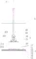
图1为本实用新型中星光吊灯模组的结构示意图;Fig. 1 is the structural representation of starlight chandelier module in the utility model;
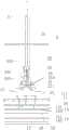
图2为本实用新型中星光吊灯模组的分解示意图;Fig. 2 is the exploded schematic diagram of the starlight chandelier module in the utility model;
图3为本实用新型中另一星光吊灯模组的分解示意图,其中出光面盖具有出光区和非出光区;3 is an exploded schematic view of another starlight chandelier module in the present invention, wherein the light-emitting surface cover has a light-emitting area and a non-light-emitting area;
图4至图7为本实用新型中星光吊灯模组的组装过程示意图,其中图4示出了背部面盖套入垂直加重杆的过程,图5示出了垂直加重杆与方形外壳组合对接的过程,图6示出了背部面盖下行安装在垂直加重杆的过程;图7示出了组装完成的方形星光吊灯模组。4 to 7 are schematic diagrams of the assembly process of the starlight chandelier module in the present invention, wherein FIG. 4 shows the process of inserting the vertical weighting rod into the back cover, and FIG. 5 shows the combined butt joint of the vertical weighting rod and the square shell. process, Figure 6 shows the process of installing the back cover down on the vertical weighting rod; Figure 7 shows the assembled square starlight chandelier module.
具体实施方式Detailed ways
为了使本技术领域的人员更好地理解本实用新型方案,下面将结合本实用新型实施例中的附图,对本实用新型实施例中的技术方案进行清楚、完整地描述,显然,所描述的实施例仅仅是本实用新型一部分的实施例,而不是全部的实施例。基于本实用新型中的实施例,本领域普通技术人员在没有做出创造性劳动前提下所获得的所有其他实施例,都应当属于本实用新型保护的范围。In order to enable those skilled in the art to better understand the solutions of the present invention, the technical solutions in the embodiments of the present invention will be described clearly and completely below with reference to the accompanying drawings in the embodiments of the present invention. Obviously, the described The embodiments are only some of the embodiments of the present invention, but not all of the embodiments. Based on the embodiments of the present invention, all other embodiments obtained by persons of ordinary skill in the art without creative work shall fall within the protection scope of the present invention.
在本实用新型的描述中,需要理解的是,术语“中心”、“纵向”、“横向”、“长度”、“宽度”、“厚度”、“上”、“下”、“前”、“后”、“左”、“右”、“竖直”、“水平”、“顶”、“底”“内”、“外”、“顺时针”、“逆时针”、“轴向”、“径向”、“周向”等指示的方位或位置关系为基于附图所示的方位或位置关系,仅是为了便于描述本实用新型和简化描述,而不是指示或暗示所指的装置或元件必须具有特定的方位、以特定的方位构造和操作,因此不能理解为对本实用新型的限制。In the description of the present invention, it should be understood that the terms "center", "longitudinal", "lateral", "length", "width", "thickness", "upper", "lower", "front", "Back", "Left", "Right", "Vertical", "Horizontal", "Top", "Bottom", "Inside", "Outside", "Clockwise", "Counterclockwise", "Axial" The orientation or positional relationship indicated by , "radial direction", "circumferential direction", etc. are based on the orientation or positional relationship shown in the accompanying drawings, which are only for the convenience of describing the present utility model and simplifying the description, rather than indicating or implying the indicated device. Or the elements must have a specific orientation, be constructed and operated in a specific orientation, and therefore should not be construed as a limitation of the present invention.
此外,术语“第一”、“第二”仅用于描述目的,而不能理解为指示或暗示相对重要性或者隐含指明所指示的技术特征的数量。由此,限定有“第一”、“第二”的特征可以明示或者隐含地包括至少一个该特征。在本实用新型的描述中,“多个”的含义是至少两个,例如两个,三个等,除非另有明确具体的限定。In addition, the terms "first" and "second" are only used for descriptive purposes, and should not be construed as indicating or implying relative importance or implying the number of indicated technical features. Thus, a feature delimited with "first", "second" may expressly or implicitly include at least one of that feature. In the description of the present invention, "plurality" means at least two, such as two, three, etc., unless otherwise expressly and specifically defined.
在本实用新型中,除非另有明确的规定和限定,术语“安装”、“相连”、“连接”、“固定”等术语应做广义理解,例如,可以是固定连接,也可以是可拆卸连接,或成一体;可以是机械连接,也可以是电连接或彼此可通讯;可以是直接相连,也可以通过中间媒介间接相连,可以是两个元件内部的连通或两个元件的相互作用关系,除非另有明确的限定。对于本领域的普通技术人员而言,可以根据具体情况理解上述术语在本实用新型中的具体含义。In the present utility model, unless otherwise expressly specified and limited, the terms "installation", "connection", "connection", "fixed" and other terms should be understood in a broad sense, for example, it may be a fixed connection or a detachable connection Connection, or integration; it can be mechanical connection, electrical connection or communication with each other; it can be directly connected or indirectly connected through an intermediate medium, it can be the internal communication between two elements or the interaction relationship between the two elements , unless otherwise expressly qualified. For those of ordinary skill in the art, the specific meanings of the above terms in the present invention can be understood according to specific situations.
如图1至7所示,本实施例提供了一种星光吊灯模组,其包括发光主体1、垂直加重杆2和背部面盖3,三者相互独立制作,且均可拆卸连接方式组合在一起。As shown in FIGS. 1 to 7 , this embodiment provides a starlight chandelier module, which includes a light-emitting body 1, a
具体地,specifically,
所述发光主体1包括:方形外壳11和设置在所述方形外壳11前部的出光面盖12,方形外壳11和出光面盖12围成承载空间;所述承载空间内设置有:LED柔性灯带13、导光板14、反光胶纸15和扩散膜16,其中,所述扩散膜16、导光板14和反光胶纸15沿出光面盖12到方形外壳背部111的方向依次设置,所述LED柔性灯带13设置在所述方形外壳11内壁上。The light-emitting body 1 includes: a
所述LED柔性灯带13包括柔性电路板131以及焊接在所述柔性电路板131上的若干LED灯珠132,LED灯珠132为顶发光模式;The LED
所述导光板14与所述LED柔性灯带13对应设置,用于将所述LED柔性灯带13发射的光导出至出光面盖12的出光区的中心。所述导光板14的侧面设置为入光面141以朝向所述LED灯珠132便于导入光线,所述导光板14的下面设置有导光板出光面142和上面设置有导光微结构网点,所述导光微结构网点用于将导入的光线进行转向使其从导光板出光面142射出,则导光板14上导入光线的方向和射出光线的方向是相互垂直的;The
所述反光胶纸15设置导光板14的上面,通过其对光反射达到提高光的亮度作用;所述扩散膜16安置在所述导光板14的下面、且在出光面盖12的上面,作用是将导光板14发出的光进行扩散实现光学扩散的效果,进一步提高出光的均匀度以及使得光照更加柔和。The
所述方形外壳背部111设置有若干导电条17,其与所述LED柔性灯带13电性连接;所述垂直加重杆2和背部面盖3均可拆卸连接在所述方形外壳背部111;所述垂直加重杆2上还设置有与外部电源线4电性连接的导电卡片21,所述导电条17与导电卡片21对应设置,当所述垂直加重杆2与方形外壳11组合对接后所述导电条17与导电卡片21电性接触实现导电。The back 111 of the square housing is provided with a plurality of
进一步地,所述方形外壳背部111与背部面盖3的可拆卸连接可以是卡扣连接、螺纹连接以及螺钉连接等等;所述方形外壳背部111与垂直加重杆2的可拆卸连接可以是插入、卡入、卡扣、粘接连接、螺纹连接以及螺钉连接等等。Further, the detachable connection between the square housing back 111 and the
进一步地,所述出光面盖12具有发光区121和非发光区122,所述出光区121与所述扩散膜16的出光面相对应;此处的发光区121和非发光区122是指透明和不透明的意思,即发光区121为透明便于光射出,而非发光区122环绕所述发光区121周边但不透光,遮光作用及提高设计的美感。Further, the light-emitting
进一步地,所述发光主体1还包括散热铝条18,其设置在所述方形外壳11和LED柔性灯带13之间,用于对所述LED柔性灯带13进行散热。Further, the light-emitting body 1 further includes a heat-dissipating
具体地,如图2、3所示,所述垂直加重杆2包括中空的加重杆22、丝杆23和喇叭件24,所述加重杆22通过丝杆23与喇叭件24对锁。Specifically, as shown in FIGS. 2 and 3 , the
所述加重杆22内中空可穿过外部电源线4,所述加重杆22远离所述方形外壳11的一头倒外角,另外一头带第一内牙221,带第一内牙221的一头利用丝杆23将其与喇叭件24对锁,其一作用是为了加重让垂吊的电源线4更加垂直,其二将发光主体1与垂直加重杆2完整组合后发光主体1更加水平,提高出光质量。The inside of the
所述喇叭件24内空心也可穿过电源线4,所述喇叭件24靠近所述加重杆22的一头开有第二内牙241便于连接丝杆23,另一头开设有锁紧槽242,锁紧槽242内开设有牙孔可利用绝缘螺丝25将其与导电卡片21固定,绝缘螺丝25能起到有效的绝缘结果,目的是不让分别引入到导电卡片21的电源短路。The hollow inside of the
如图2、3、4、5所示,所述导电卡片21设置在所述喇叭件24远离所述加重杆22的一侧,具体是通过绝缘螺丝25固定在所述所述喇叭件24上;所述导电卡片21一端固定稳固在所述喇叭件24上,另一端向外延伸形成卡耳211,其会凸出喇叭件24的周边,对应地所述方形外壳背部111对应设置有卡槽112,便于与卡耳211实现插入或卡入的吻合对接。所述卡槽112内设置有导电条17,当导电卡片21的卡耳211对接到卡槽112内,则导电卡片21与导电条17对接导通。进一步地,所述导电卡片21在其的边上或里面设有向上形成的导电凸耳212,导电凸耳212的作用与外部电源线4连接通电。通过如上的设计,其一作用是将垂直加重杆2与发光主体1组合对接后直接可以导电,进而实现外部电源线4与LED柔性灯带13的导通,其二使垂直加重杆2与发光主体1组合容易拆卸对接,使组装和日后保养及检修更方便。As shown in FIGS. 2 , 3 , 4 and 5 , the
具体地,如图4至7所示,所述背部面盖3中部开设有通孔31,所述背部面盖3通过通孔31套入所述垂直加重杆2后与所述方形外壳11连接,可以理解为一块绝缘材料中间带有通孔31的盖片。简单的说是一种装饰盖片遮丑作用,其材质采用绝缘材料即可,绝缘材料能起到有效的绝缘效果,目的是担心背部面盖3将导电卡片21的正负极接触短路。Specifically, as shown in FIGS. 4 to 7 , a through
作为优选方式,所述方形外壳11、导光板14、出光面盖12和背部面盖3的材质为PC材质但不局限于此,所述喇叭件24的材质为PC材质但不局限于此,所述导电条17和导电卡片21材质均优选但不限定为铜材。As a preferred way, the material of the
显然,以上所描述的实施例仅仅是本申请一部分实施例,而不是全部的实施例,附图中给出了本申请的较佳实施例,但并不限制本申请的专利范围。本申请可以以许多不同的形式来实现,相反地,提供这些实施例的目的是使对本申请的公开内容的理解更加透彻全面。尽管参照前述实施例对本申请进行了详细的说明,对于本领域的技术人员来而言,其依然可以对前述各具体实施方式所记载的技术方案进行修改,或者对其中部分技术特征进行等效替换。凡是利用本申请说明书及附图内容所做的等效结构,直接或间接运用在其他相关的技术领域,均同理在本申请专利保护范围之内。Obviously, the above-described embodiments are only a part of the embodiments of the present application, rather than all of the embodiments. The accompanying drawings show the preferred embodiments of the present application, but do not limit the scope of the patent of the present application. This application may be embodied in many different forms, rather these embodiments are provided so that a thorough and complete understanding of the disclosure of this application is provided. Although the present application has been described in detail with reference to the foregoing embodiments, those skilled in the art can still modify the technical solutions described in the foregoing specific embodiments, or perform equivalent replacements for some of the technical features. . Any equivalent structure made by using the contents of the description and drawings of the present application, which is directly or indirectly used in other related technical fields, is also within the scope of protection of the patent of the present application.
Claims (8)
Priority Applications (1)
| Application Number | Priority Date | Filing Date | Title |
|---|---|---|---|
| CN201921932143.0UCN210717230U (en) | 2019-11-08 | 2019-11-08 | A starlight chandelier module |
Applications Claiming Priority (1)
| Application Number | Priority Date | Filing Date | Title |
|---|---|---|---|
| CN201921932143.0UCN210717230U (en) | 2019-11-08 | 2019-11-08 | A starlight chandelier module |
Publications (1)
| Publication Number | Publication Date |
|---|---|
| CN210717230Utrue CN210717230U (en) | 2020-06-09 |
Family
ID=70928833
Family Applications (1)
| Application Number | Title | Priority Date | Filing Date |
|---|---|---|---|
| CN201921932143.0UExpired - Fee RelatedCN210717230U (en) | 2019-11-08 | 2019-11-08 | A starlight chandelier module |
Country Status (1)
| Country | Link |
|---|---|
| CN (1) | CN210717230U (en) |
- 2019
- 2019-11-08CNCN201921932143.0Upatent/CN210717230U/ennot_activeExpired - Fee Related
Similar Documents
| Publication | Publication Date | Title |
|---|---|---|
| US8186845B2 (en) | LED lamp | |
| US20090034257A1 (en) | High-power light emitting diode (led) street lamp and body frame thereof | |
| US20090016055A1 (en) | High-power light emitting diode (led) street lamp and body frame thereof | |
| US11193660B2 (en) | Optical element, a lighting apparatus and a lighting lamp with the lighting apparatus | |
| US10048433B2 (en) | Flat panel lighting apparatus | |
| US20150205030A1 (en) | Panel light | |
| JP3157514U (en) | Double sided LED lighting device | |
| CN204403966U (en) | Ligthing paraphernalia and secondary light source unit | |
| CN109488918B (en) | LED linear lamp | |
| US20030142492A1 (en) | Apparatus and manufacturing method for border lighting | |
| CN105180032A (en) | A lighting fixture and a lighting fixture combination | |
| KR100945175B1 (en) | Led lighting apparatus | |
| CN210717230U (en) | A starlight chandelier module | |
| CN210662573U (en) | Moon ceiling lamp module | |
| JP2016076402A (en) | Electrical device and method for manufacturing the same | |
| CN209782308U (en) | Shadow-free linear LED lamp | |
| CN109210504B (en) | Mounting bracket and LED line lamp | |
| CN209229370U (en) | One-piece lens semi-encapsulated LED module | |
| JP2011204845A (en) | Light emitting device | |
| JP3186638U (en) | Light-sensitive dimming lamp | |
| CN208011451U (en) | Floodlight | |
| JP3212763U (en) | LED lights | |
| CN210069530U (en) | LED three-dimensional transparent light-emitting lamp | |
| JP2011054421A (en) | Lighting article | |
| CN219433142U (en) | Novel flat lamp without frame |
Legal Events
| Date | Code | Title | Description |
|---|---|---|---|
| GR01 | Patent grant | ||
| GR01 | Patent grant | ||
| CF01 | Termination of patent right due to non-payment of annual fee | ||
| CF01 | Termination of patent right due to non-payment of annual fee | Granted publication date:20200609 Termination date:20201108 |