CN210490508U - A smart glasses system and power supply device for electronic equipment - Google Patents
A smart glasses system and power supply device for electronic equipmentDownload PDFInfo
- Publication number
- CN210490508U CN210490508UCN201921716809.9UCN201921716809UCN210490508UCN 210490508 UCN210490508 UCN 210490508UCN 201921716809 UCN201921716809 UCN 201921716809UCN 210490508 UCN210490508 UCN 210490508U
- Authority
- CN
- China
- Prior art keywords
- power supply
- battery
- controller
- bus
- output switch
- Prior art date
- Legal status (The legal status is an assumption and is not a legal conclusion. Google has not performed a legal analysis and makes no representation as to the accuracy of the status listed.)
- Active
Links
- 239000004984smart glassSubstances0.000titleclaimsdescription52
- 239000011521glassSubstances0.000abstractdescription2
- 238000010586diagramMethods0.000description6
- 238000000034methodMethods0.000description3
- 238000007792additionMethods0.000description1
- 238000007599dischargingMethods0.000description1
- 238000010295mobile communicationMethods0.000description1
- 238000012986modificationMethods0.000description1
- 230000004048modificationEffects0.000description1
- 230000008092positive effectEffects0.000description1
- 230000001960triggered effectEffects0.000description1
Images


Landscapes
- Charge And Discharge Circuits For Batteries Or The Like (AREA)
- Direct Current Feeding And Distribution (AREA)
Abstract
Description
Translated fromChinese技术领域technical field
本实用新型涉及电子设备供电技术领域,具体地说,是涉及一种智能眼镜系统及电子设备的供电装置。The utility model relates to the technical field of power supply for electronic equipment, in particular to a smart glasses system and a power supply device for electronic equipment.
背景技术Background technique
目前,智能眼镜应用到了越来越多的领域,智能眼镜一般采用电池供电。但是,智能眼镜一般都是功耗大,采用电池供电方式存在续航时间短的问题,因而,无法将智能眼镜应用于对于续航要求高的工业或医疗场景。有的智能眼镜为了提高续航时间,采用外部供电的设备,需要使用线缆连接到交流适配器或其他供电设施,失去了智能眼镜的灵活性和便利性。At present, smart glasses are applied to more and more fields, and smart glasses are generally powered by batteries. However, smart glasses generally consume a lot of power, and the battery power supply method has the problem of short battery life. Therefore, smart glasses cannot be applied to industrial or medical scenarios that require high battery life. In order to improve battery life, some smart glasses use externally powered devices and need to use cables to connect to AC adapters or other power supply facilities, which loses the flexibility and convenience of smart glasses.
发明内容SUMMARY OF THE INVENTION
本实用新型提出了一种电子设备的供电装置的硬件电路和智能眼镜系统,解决了续航要求高的电子设备,例如智能眼镜使用线缆连接到交流适配器或其他供电设施,失去灵活性和便利性的技术问题。The utility model proposes a hardware circuit of a power supply device for electronic equipment and a smart glasses system, which solves the problem that electronic equipment with high battery life requirements, such as smart glasses connected to an AC adapter or other power supply facilities using cables, loses flexibility and convenience technical issues.
为了解决上述技术问题,本实用新型采用以下技术方案予以实现:In order to solve the above-mentioned technical problems, the utility model adopts the following technical solutions to be realized:
一种电子设备的供电装置,包括:A power supply device for electronic equipment, comprising:
供电接口,用于输出电能至所述电子设备,所述供电接口连接系统电源总线;a power supply interface for outputting electrical energy to the electronic device, and the power supply interface is connected to a system power bus;
预置电源,所述预置电源通过第一输出开关与所述系统电源总线相接;a preset power supply, which is connected to the system power bus through a first output switch;
至少一个电池插座,所述电池插座用于安装电池且与所述系统电源总线相接;at least one battery socket, the battery socket is used to install a battery and is connected to the system power bus;
第一控制器,所述电池插座通过第一信号总线、第二信号总线与所述第一控制器相接,所述第一控制器通过信号线与所述第一输出开关相接。A first controller, the battery socket is connected to the first controller through a first signal bus and a second signal bus, and the first controller is connected to the first output switch through a signal line.
如上所述的供电装置,所述第一输出开关的输入接口连接至系统电源总线、输出接口连接至所述预置电源、控制接口连接至所述第一控制器。In the above power supply device, the input interface of the first output switch is connected to the system power bus, the output interface is connected to the preset power supply, and the control interface is connected to the first controller.
如上所述的供电装置,所述电池插座包括第二输出开关,所述第二输出开关包括第二控制器,所述第一控制器通过所述第一信号总线和所述第二信号总线与所述第二输出开关相接;In the above power supply device, the battery socket includes a second output switch, the second output switch includes a second controller, and the first controller communicates with the first controller through the first signal bus and the second signal bus. the second output switches are connected;
或者,or,
所述电池插座包括第三输出开关和第三控制器,所述第三输出开关的输入接口用于连接至所述电池、输出接口连接至所述系统电源总线、控制接口连接至所述第三控制器;所述第一控制器通过所述第一信号总线和所述第二信号总线与所述第三控制器相接。The battery socket includes a third output switch and a third controller, the input interface of the third output switch is used to connect to the battery, the output interface is connected to the system power bus, and the control interface is connected to the third a controller; the first controller is connected to the third controller through the first signal bus and the second signal bus.
如上所述的供电装置,所述供电装置包括插接在所述电池插座上的电池;The above-mentioned power supply device, the power supply device comprises a battery plugged into the battery socket;
所述电池包括第四输出开关,所述第四输出开关包括第四控制器,所述第一控制器通过所述第一信号总线和所述第二信号总线经由所述电池插座与所述第四输出开关相接;The battery includes a fourth output switch, the fourth output switch includes a fourth controller, and the first controller communicates with the first controller via the battery socket via the first signal bus and the second signal bus. Four output switches are connected;
或者,or,
所述电池包括第五输出开关和第五控制器,所述第五输出开关的输入接口连接至所述电池、输出接口经由所述电池插座连接至所述系统电源总线、控制接口连接至所述第五控制器;所述第一控制器通过所述第一信号总线和所述第二信号总线经由所述电池插座与所述第五控制器相接。The battery includes a fifth output switch and a fifth controller, an input interface of the fifth output switch is connected to the battery, an output interface is connected to the system power bus via the battery socket, and a control interface is connected to the battery A fifth controller; the first controller is connected to the fifth controller via the battery socket through the first signal bus and the second signal bus.
如上所述的供电装置,所述第一信号总线为I2C总线,所述I2C总线存储所述电池插座的地址信息,所述第一控制器根据所述地址信息通过所述I2C总线获取所述电池的状态信息。In the above power supply device, the first signal bus is an I2C bus, the I2C bus stores address information of the battery socket, and the first controller obtains the battery through the I2C bus according to the address information status information.
如上所述的供电装置,所述供电装置包括柔性连接装置。In the above-mentioned power supply device, the power supply device includes a flexible connection device.
如上所述的供电装置,所述柔性连接装置为腰带或者臂带。In the above-mentioned power supply device, the flexible connection device is a belt or an armband.
一种智能眼镜系统,所述智能眼镜系统包括智能眼镜和上述的电子设备的供电装置,所述供电装置通过电源线与所述智能眼镜相接。A smart glasses system, the smart glasses system includes smart glasses and the above-mentioned power supply device for electronic equipment, the power supply device is connected to the smart glasses through a power cord.
如上所述的智能眼镜系统,所述智能眼镜系统还包括信号线,所述供电装置通过所述信号线与所述智能眼镜相接,用于通过所述信号线向所述智能眼镜传输温度信息、电量信息、低电压报警信息、和/或电池切换提醒信息。In the above smart glasses system, the smart glasses system further comprises a signal line, the power supply device is connected to the smart glasses through the signal line, and is used for transmitting temperature information to the smart glasses through the signal line , battery information, low voltage alarm information, and/or battery switching reminder information.
如上所述的智能眼镜系统,所述信号线与所述电源线为USB线缆。In the above smart glasses system, the signal line and the power line are USB cables.
与现有技术相比,本实用新型的优点和积极效果是:本实用新型电子设备的供电装置包括预置电源和至少一个电池插座,电池插座用于安装电池,采用电池作为电源,保留了电池设备的可移动性,保证了电子设备的灵活性和便利性。同时,本实用新型的预置电源可以保证更换电池时无需关机,保证了电子设备高功耗前提下的续航能力。Compared with the prior art, the advantages and positive effects of the present invention are as follows: the power supply device of the electronic device of the present invention includes a preset power supply and at least one battery socket, the battery socket is used for installing the battery, the battery is used as the power source, and the battery is reserved. The mobility of the device ensures the flexibility and convenience of electronic devices. At the same time, the preset power supply of the present invention can ensure that the battery does not need to be shut down when replacing the battery, thereby ensuring the battery life of the electronic device under the premise of high power consumption.
本实用新型智能眼镜系统的供电装置能够保证智能眼镜的灵活性和便利性,保证高功耗前提下的续航能力。The power supply device of the smart glasses system of the utility model can ensure the flexibility and convenience of the smart glasses, and ensure the battery life under the premise of high power consumption.
结合附图阅读本实用新型实施方式的详细描述后,本实用新型的其他特点和优点将变得更加清楚。Other features and advantages of the present invention will become more apparent after reading the detailed description of the embodiments of the present invention in conjunction with the accompanying drawings.
附图说明Description of drawings
为了更清楚地说明本实用新型实施例或现有技术中的技术方案,下面将对实施例或现有技术描述中所需要使用的附图作简单地介绍,显而易见地,下面描述中的附图仅仅是本实用新型的一些实施例,对于本领域普通技术人员来讲,在不付出创造性劳动的前提下,还可以根据这些附图获得其他的附图。In order to more clearly illustrate the embodiments of the present utility model or the technical solutions in the prior art, the following briefly introduces the accompanying drawings that need to be used in the description of the embodiments or the prior art. Obviously, the accompanying drawings in the following description These are just some embodiments of the present invention, and for those of ordinary skill in the art, other drawings can also be obtained from these drawings without creative effort.
图1是本实用新型第一具体实施例供电装置的电路图。FIG. 1 is a circuit diagram of a power supply device according to a first specific embodiment of the present invention.
图2是本实用新型第二具体实施例供电装置的电路图。FIG. 2 is a circuit diagram of a power supply device according to a second embodiment of the present invention.
图3是本实用新型第三具体实施例供电装置的电路图。FIG. 3 is a circuit diagram of a power supply device according to a third embodiment of the present invention.
图4是本实用新型第四具体实施例供电装置的电路图。FIG. 4 is a circuit diagram of a power supply device according to a fourth embodiment of the present invention.
图5是本发明具体实施例第一控制器、供电接口、预置电源和第一输出开关部分的电路图。5 is a circuit diagram of a first controller, a power supply interface, a preset power supply and a first output switch part according to a specific embodiment of the present invention.
图6是本实用新型具体实施例智能眼镜系统的示意图。6 is a schematic diagram of a smart glasses system according to a specific embodiment of the present invention.
具体实施方式Detailed ways
下面将结合本实用新型实施例中的附图,对本实用新型实施例中的技术方案进行清楚、完整地描述,显然,所描述的实施例仅仅是本实用新型一部分实施例,而不是全部的实施例。基于本实用新型中的实施例,本领域普通技术人员在没有做出创造性劳动前提下所获得的所有其他实施例,都属于本实用新型保护的范围。The technical solutions in the embodiments of the present utility model will be clearly and completely described below with reference to the accompanying drawings in the embodiments of the present utility model. Obviously, the described embodiments are only a part of the embodiments of the present utility model, rather than all the implementations. example. Based on the embodiments of the present invention, all other embodiments obtained by those of ordinary skill in the art without creative work fall within the protection scope of the present invention.
本实施例提出了一种电子设备的供电装置及采用供电装置的智能眼镜系统。This embodiment provides a power supply device for electronic equipment and a smart glasses system using the power supply device.
电子设备的供电装置包括预置电源和至少一个电池插座,电池插座用于安装电池,采用电池作为电源,保留了电池设备的可移动性,保证了电子设备的灵活性和便利性。同时,预置电源可以保证更换电池时无需关机,保证了电子设备高功耗前提下的续航能力。The power supply device of the electronic device includes a preset power supply and at least one battery socket, the battery socket is used for installing the battery, and the battery is used as the power source, which preserves the mobility of the battery device and ensures the flexibility and convenience of the electronic device. At the same time, the preset power supply can ensure that there is no need to shut down the battery when replacing the battery, which ensures the battery life of the electronic device under the premise of high power consumption.
智能眼镜具有独立的操作系统,可以由用户安装软件、游戏等软件服务商提供的程序,可通过语音或动作操控完成添加日程、地图导航、与好友互动、拍摄照片和视频、与朋友展开视频通话等功能,并可以通过移动通讯网络来实现无线网络接入的一类眼镜。智能眼镜系统采用电子设备的供电装置后,可满足其使用场景的灵活性和便利性,并且大大提高续航能力。Smart glasses have an independent operating system, and users can install programs provided by software service providers such as software and games, and can add schedules, map navigation, interact with friends, take photos and videos, and start video calls with friends through voice or motion control. A class of glasses that can achieve wireless network access through mobile communication networks. After the smart glasses system adopts the power supply device of electronic equipment, it can meet the flexibility and convenience of its use scene, and greatly improve the battery life.
下面,以智能眼镜系统及智能眼镜的供电装置为例对本实用新型的实现方式进行说明,当然,供电装置的供电对象并不限定在智能眼镜,供电装置还可以为其他电子设备供电。Hereinafter, the implementation of the present invention will be described by taking the smart glasses system and the power supply device of the smart glasses as examples. Of course, the power supply object of the power supply device is not limited to the smart glasses, and the power supply device can also supply power to other electronic devices.
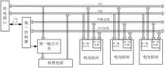
如图1-4所示,一种智能眼镜的供电装置,包括供电接口、预置电源、至少一个电池插座和第一控制器,下面对供电装置的各组成部分分别进行说明:As shown in Figure 1-4, a power supply device for smart glasses includes a power supply interface, a preset power supply, at least one battery socket and a first controller. The components of the power supply device are described below:
供电接口,用于输出电能至智能眼镜,供电接口连接系统电源总线。供电接口能够接收预置电源或者电池插座提供的电能并将电能输出。供电接口可直接与智能眼镜相接,直接输出电能给智能眼镜供电,或者,供电接口通过电缆与智能眼镜相接,输出的电能通过电缆给智能眼镜供电。由于智能眼镜直接戴在人脸上,优选采用电缆的方式。为了提高供电接口的通用性,供电接口优选采用USB接口。The power supply interface is used to output power to the smart glasses, and the power supply interface is connected to the system power bus. The power supply interface can receive the power provided by the preset power supply or the battery socket and output the power. The power supply interface can be directly connected with the smart glasses, and directly output electric energy to supply power to the smart glasses, or the power supply interface can be connected with the smart glasses through a cable, and the output electric energy can supply power to the smart glasses through the cable. Since the smart glasses are directly worn on the face, the cable is preferred. In order to improve the versatility of the power supply interface, the power supply interface preferably adopts a USB interface.
预置电源,预置电源通过第一输出开关与系统电源总线相接,第一输出开关导通时,供电接口能够接收预置电源提供的电能并将电能输出。第一输出开关断开时,供电接口与预置电源断开。The preset power supply is connected to the system power bus through the first output switch. When the first output switch is turned on, the power supply interface can receive the electric energy provided by the preset power supply and output the electric energy. When the first output switch is disconnected, the power supply interface is disconnected from the preset power supply.
优选的,预置电源采用可充电电源,在智能眼镜不使用时,可对预置电源进行充电。Preferably, the preset power source is a rechargeable power source, and the preset power source can be charged when the smart glasses are not in use.
至少一个电池插座,电池插座通过系统电源总线与供电接口相接,电池插座用于安装电池。电池插座安装电池后,能够输出电池的电能至供电接口。At least one battery socket, the battery socket is connected with the power supply interface through the system power bus, and the battery socket is used to install the battery. After the battery is installed in the battery socket, the power of the battery can be output to the power supply interface.
第一控制器,电池插座通过第一信号总线、第二信号总线与第一控制器相接,第一控制器通过信号线与第一输出开关相接。如图5所示,第一输出开关的输入接口连接至系统电源总线、输出接口连接至预置电源、控制接口连接至第一控制器。The first controller, the battery socket is connected with the first controller through the first signal bus and the second signal bus, and the first controller is connected with the first output switch through the signal line. As shown in FIG. 5 , the input interface of the first output switch is connected to the system power bus, the output interface is connected to the preset power supply, and the control interface is connected to the first controller.
第一信号总线为I2C总线, I2C总线存储所述电池插座的地址信息,第一控制器根据地址信息通过I2C总线获取电池的状态信息。The first signal bus is an I2C bus, the I2C bus stores address information of the battery socket, and the first controller obtains the status information of the battery through the I2C bus according to the address information.
第二信号总线为中断信号总线。The second signal bus is an interrupt signal bus.
如图1所示,电池插座包括第二输出开关,第二输出开关包括第二控制器,第二控制器设置在第二输出开关内部。第一控制器通过第一信号总线和第二信号总线与第二输出开关相接。第一控制器通过第二控制器控制第二输出开关的导通和断开,第二输出开关导通时,供电接口能够接收电池插座提供的电能并将电能输出,第二输出开关断开时,供电接口与电池插座断开。As shown in FIG. 1 , the battery socket includes a second output switch, the second output switch includes a second controller, and the second controller is arranged inside the second output switch. The first controller is connected to the second output switch through the first signal bus and the second signal bus. The first controller controls the on and off of the second output switch through the second controller. When the second output switch is on, the power supply interface can receive the power provided by the battery socket and output the power, and when the second output switch is off , the power supply interface is disconnected from the battery socket.
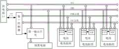
如图2所示,电池插座包括第三输出开关和第三控制器,第三输出开关和第三控制器并列设置。第三输出开关的输入接口用于连接至电池、输出接口连接至系统电源总线、控制接口连接至第三控制器;第一控制器通过第一信号总线和第二信号总线与第三控制器相接。第三控制器控制第三输出开关的导通和断开,第三输出开关导通时,供电接口能够接收电池插座提供的电能并将电能输出,第三输出开关断开时,供电接口与电池插座断开。电池插座包括输出开关时,在输出开关导通时,供电接口能够接收电池插座提供的电能并将电能输出,在输出开关断开时,供电接口与电池插座断开。As shown in FIG. 2 , the battery socket includes a third output switch and a third controller, and the third output switch and the third controller are arranged in parallel. The input interface of the third output switch is used to connect to the battery, the output interface is connected to the system power bus, and the control interface is connected to the third controller; the first controller is connected to the third controller through the first signal bus and the second signal bus catch. The third controller controls the turn-on and turn-off of the third output switch. When the third output switch is turned on, the power supply interface can receive the power provided by the battery socket and output the power. When the third output switch is turned off, the power supply interface and the battery The socket is disconnected. When the battery socket includes an output switch, when the output switch is turned on, the power supply interface can receive the power provided by the battery socket and output the power, and when the output switch is turned off, the power supply interface is disconnected from the battery socket.
如图3所示,供电装置包括插接在电池插座上的电池,电池包括第四输出开关。第四输出开关包括第四控制器,第四控制器设置在第四输出开关的内部。第一控制器通过第一信号总线和第二信号总线经由电池插座与第四输出开关相接;第一控制器通过第四控制器控制第二输出开关的导通和断开,第二输出开关导通时,供电接口能够接收电池插座提供的电能并将电能输出,第二输出开关断开时,供电接口与电池插座断开。As shown in FIG. 3 , the power supply device includes a battery inserted into the battery socket, and the battery includes a fourth output switch. The fourth output switch includes a fourth controller, and the fourth controller is arranged inside the fourth output switch. The first controller is connected to the fourth output switch via the battery socket through the first signal bus and the second signal bus; the first controller controls the conduction and disconnection of the second output switch through the fourth controller, and the second output switch When turned on, the power supply interface can receive the power provided by the battery socket and output the power, and when the second output switch is off, the power supply interface is disconnected from the battery socket.
如图4所示,电池包括第五输出开关和第五控制器,第五输出开关和第五控制器并列设置。第五输出开关的输入接口连接至电池、输出接口经由电池插座连接至系统电源总线、控制接口连接至第五控制器;第一控制器通过第一信号总线和第二信号总线经由电池插座与第五控制器相接。第五控制器控制第五输出开关的导通和断开,第五输出开关导通时,供电接口能够接收电池插座提供的电能并将电能输出,第五输出开关断开时,供电接口与电池插座断开。As shown in FIG. 4 , the battery includes a fifth output switch and a fifth controller, and the fifth output switch and the fifth controller are arranged in parallel. The input interface of the fifth output switch is connected to the battery, the output interface is connected to the system power bus through the battery socket, and the control interface is connected to the fifth controller; the first controller communicates with the first controller through the first signal bus and the second signal bus through the battery socket. The five controllers are connected. The fifth controller controls the on and off of the fifth output switch. When the fifth output switch is on, the power supply interface can receive the power provided by the battery socket and output the power. When the fifth output switch is off, the power supply interface and the battery The socket is disconnected.
电池包括输出开关时,在输出开关导通时,供电接口能够接收电池提供的电能并将电能输出,在输出开关断开时,供电接口与电池断开。When the battery includes an output switch, when the output switch is turned on, the power supply interface can receive the electrical energy provided by the battery and output the electrical energy, and when the output switch is off, the power supply interface is disconnected from the battery.
优选的,电池为可充电电池。Preferably, the battery is a rechargeable battery.
下面对供电装置的供电过程进行说明:The following describes the power supply process of the power supply device:
第一控制器在I2C总线上检测不到电池插座上插装电池,或电池插座上的电池都为低电量状态,控制器输出控制信号控制第一输出开关导通,预置电源输出电能至供电接口。The first controller cannot detect that the battery socket is inserted into the battery socket on the I2 C bus, or the batteries on the battery socket are all in a low power state, the controller outputs a control signal to control the first output switch to be turned on, and the preset power supply outputs electric energy to the power supply interface.
用户将电池插入到电池插座时,电池通过中断信号总线将控制器唤醒;第一控制器通过I2C总线获取电池信息,如果电池信息正常,并且没有已经在供电的电池,则第一控制器通过I2C总线输出控制信号控制新插入的电池对应的第二输出开关导通,第一控制器输出控制信号控制第一输出开关断开,新插入的电池输出电能至供电接口。When the user inserts the battery into the battery socket, the battery wakes up the controller through the interrupt signal bus; the first controller obtains the battery information through the I2 C bus, if the battery information is normal and there is no battery that is already supplying power, the first controller will The I2 C bus outputs a control signal to control the second output switch corresponding to the newly inserted battery to be turned on, the first controller outputs a control signal to control the first output switch to be turned off, and the newly inserted battery outputs power to the power supply interface.
如果已经存在正在放电的电池,可将新插入的电池作为备用电源,电池插座或者电池的输出开关断开。If there is already a discharging battery, the newly inserted battery can be used as a backup power source, and the battery socket or the output switch of the battery is disconnected.
电池拔出后,触发控制器欠压事件,第一控制器输出控制信号控制第一输出开关导通,预置电源输出电能至供电接口。之后控制器重新扫描电池插座,如果有可使用的电池存在,则切换到电池供电。After the battery is pulled out, the controller undervoltage event is triggered, the first controller outputs a control signal to control the first output switch to be turned on, and the preset power supply outputs electric energy to the power supply interface. The controller then rescans the battery socket and switches to battery power if there is a usable battery.
当电池电压较低时,通过中断总线发送请求,使用I2C总线进行低电压报警,第一控制器查询I2C总线上电池的电量状态,进行电源切换。When the battery voltage is low, a request is sent through the interrupt bus, and the I2 C bus isused for low voltage alarm.
为了对供电装置进行固定,供电装置包括柔性连接装置,供电装置通过柔性连接装置固定在人体上。In order to fix the power supply device, the power supply device includes a flexible connection device, and the power supply device is fixed on the human body through the flexible connection device.
优选的,柔性连接装置为腰带或者臂带。Preferably, the flexible connecting device is a waist belt or an armband.
如图6所示,本实施例还提出了一种智能眼镜系统,智能眼镜系统包括智能眼镜和上述的供电装置,供电装置通过电源线与智能眼镜相接。As shown in FIG. 6 , a smart glasses system is also proposed in this embodiment. The smart glasses system includes smart glasses and the above-mentioned power supply device. The power supply device is connected to the smart glasses through a power cord.
智能眼镜系统还包括信号线,供电装置通过信号线与智能眼镜相接,用于通过所述信号线向所述智能眼镜传输温度信息、电量信息、低电压报警信息、和/或电池切换提醒信息。The smart glasses system further includes a signal line, and the power supply device is connected to the smart glasses through the signal line, and is used to transmit temperature information, power information, low voltage alarm information, and/or battery switching reminder information to the smart glasses through the signal line .
为了提高通用性,信号线与电源线为USB线缆。In order to improve the versatility, the signal line and the power line are USB cables.
当然,上述说明并非是对本实用新型的限制,本实用新型也并不仅限于上述举例,本技术领域的普通技术人员在本实用新型的实质范围内所做出的变化、改型、添加或替换,也应属于本实用新型的保护范围。Of course, the above description is not a limitation of the present utility model, and the present utility model is not limited to the above-mentioned examples. The changes, modifications, additions or replacements made by those of ordinary skill in the art within the essential scope of the present utility model, It should also belong to the protection scope of the present invention.
Claims (10)
Translated fromChinesePriority Applications (1)
| Application Number | Priority Date | Filing Date | Title |
|---|---|---|---|
| CN201921716809.9UCN210490508U (en) | 2019-10-14 | 2019-10-14 | A smart glasses system and power supply device for electronic equipment |
Applications Claiming Priority (1)
| Application Number | Priority Date | Filing Date | Title |
|---|---|---|---|
| CN201921716809.9UCN210490508U (en) | 2019-10-14 | 2019-10-14 | A smart glasses system and power supply device for electronic equipment |
Publications (1)
| Publication Number | Publication Date |
|---|---|
| CN210490508Utrue CN210490508U (en) | 2020-05-08 |
Family
ID=70509744
Family Applications (1)
| Application Number | Title | Priority Date | Filing Date |
|---|---|---|---|
| CN201921716809.9UActiveCN210490508U (en) | 2019-10-14 | 2019-10-14 | A smart glasses system and power supply device for electronic equipment |
Country Status (1)
| Country | Link |
|---|---|
| CN (1) | CN210490508U (en) |
Cited By (1)
| Publication number | Priority date | Publication date | Assignee | Title |
|---|---|---|---|---|
| CN111555086A (en)* | 2020-05-21 | 2020-08-18 | Oppo广东移动通信有限公司 | Signal transmission cable and intelligent glasses |
- 2019
- 2019-10-14CNCN201921716809.9Upatent/CN210490508U/enactiveActive
Cited By (1)
| Publication number | Priority date | Publication date | Assignee | Title |
|---|---|---|---|---|
| CN111555086A (en)* | 2020-05-21 | 2020-08-18 | Oppo广东移动通信有限公司 | Signal transmission cable and intelligent glasses |
Similar Documents
| Publication | Publication Date | Title |
|---|---|---|
| CN104917016A (en) | Charging type concentrator | |
| CN103746434A (en) | Charging method and charging system | |
| CN104253456A (en) | Charging apparatus, power supply method, terminal device and charging method | |
| CN105762898A (en) | Intelligent mobile phone charger | |
| US10164461B2 (en) | Wireless charging device, system, and method based on back cover mobile power supply | |
| CN108964162A (en) | A kind of battery management system wake-up system and a kind of DC/DC converter | |
| CN109510045B (en) | A USB data cable with auxiliary power supply | |
| CN105208518A (en) | Wireless router device, wireless router system and communication method | |
| CN210490508U (en) | A smart glasses system and power supply device for electronic equipment | |
| CN104767277A (en) | A digital power management system for exoskeleton robots | |
| CN104167790B (en) | The charge control system and its charge control method of charger, mobile terminal | |
| CN204992701U (en) | Quick charging device of portable power source | |
| CN110311438A (en) | Charging device and operation method thereof | |
| CN106453513A (en) | Internet of Things (IOT) device | |
| CN220368488U (en) | Plug-in type battery module | |
| CN209658936U (en) | Fully charged charging device | |
| CN103607026A (en) | Intelligent switch with wireless charging function and charging method | |
| CN104283289B (en) | A kind of Bluetooth charging device and charge control method | |
| CN203851047U (en) | Minisize intelligent AC-DC composite power supply for distributed base station | |
| CN214850615U (en) | Device for supplying power to CPE and small base station | |
| WO2016173081A1 (en) | Method and device for implementing connection control | |
| CN210430980U (en) | Rechargeable battery power supply device | |
| CN209963779U (en) | Power adapter | |
| CN209298917U (en) | Power supply unit and electronic equipment | |
| CN103532173A (en) | Mobile equipment and charging system with the same |
Legal Events
| Date | Code | Title | Description |
|---|---|---|---|
| GR01 | Patent grant | ||
| GR01 | Patent grant | ||
| TR01 | Transfer of patent right | Effective date of registration:20201103 Address after:261031 north of Yuqing street, east of Dongming Road, high tech Zone, Weifang City, Shandong Province (Room 502, Geer electronic office building) Patentee after:GoerTek Optical Technology Co.,Ltd. Address before:261205 Shandong province Weifang Comprehensive Bonded Zone Yuqing East Street to South High Tech two Road East Weifang Comprehensive Bonded Zone aide light industrial product processing base 1, 3, 5 workshop Patentee before:Weifang Goertek Electronics Co.,Ltd. | |
| TR01 | Transfer of patent right | ||
| TR01 | Transfer of patent right | Effective date of registration:20221220 Address after:266104 No. 500, Songling Road, Laoshan District, Qingdao, Shandong Patentee after:GOERTEK TECHNOLOGY Co.,Ltd. Address before:261031 north of Yuqing street, east of Dongming Road, high tech Zone, Weifang City, Shandong Province (Room 502, Geer electronics office building) Patentee before:GoerTek Optical Technology Co.,Ltd. | |
| TR01 | Transfer of patent right |