CN210142300U - A computer case with self-dusting function - Google Patents
A computer case with self-dusting functionDownload PDFInfo
- Publication number
- CN210142300U CN210142300UCN201921612750.9UCN201921612750UCN210142300UCN 210142300 UCN210142300 UCN 210142300UCN 201921612750 UCN201921612750 UCN 201921612750UCN 210142300 UCN210142300 UCN 210142300U
- Authority
- CN
- China
- Prior art keywords
- case
- air inlet
- filter screen
- face
- self
- Prior art date
- Legal status (The legal status is an assumption and is not a legal conclusion. Google has not performed a legal analysis and makes no representation as to the accuracy of the status listed.)
- Expired - Fee Related
Links
- 238000010410dustingMethods0.000titleabstractdescription7
- 238000007789sealingMethods0.000claimsabstractdescription18
- 239000000428dustSubstances0.000claimsabstractdescription13
- 230000017525heat dissipationEffects0.000claimsdescription4
- 238000004140cleaningMethods0.000abstractdescription5
- 238000001816coolingMethods0.000description9
- 238000012986modificationMethods0.000description2
- 230000004048modificationEffects0.000description2
- 238000009825accumulationMethods0.000description1
- 230000009286beneficial effectEffects0.000description1
- 238000010586diagramMethods0.000description1
- 230000000694effectsEffects0.000description1
- 238000001914filtrationMethods0.000description1
- 238000009434installationMethods0.000description1
- 230000007774longtermEffects0.000description1
- 238000000034methodMethods0.000description1
Images

Landscapes
- Filtering Of Dispersed Particles In Gases (AREA)
Abstract
Translated fromChinese
Description
Translated fromChinese技术领域technical field
本实用新型涉及计算机机箱除尘技术领域,具体为一种具有自除尘功能的计算机机箱。The utility model relates to the technical field of dust removal of a computer case, in particular to a computer case with a self-dusting function.
背景技术Background technique
计算机的机箱由于长期的使用,导致内部会聚集大量灰尘,同时由于机箱内部需要及时的散热,从而需要对机箱内腔进行不断的进气,用以实现散热,这样就容易导致灰尘持续进入机箱。Due to the long-term use of the computer case, a large amount of dust will accumulate inside. At the same time, since the inside of the case needs to be dissipated in time, it is necessary to continuously inhale the air into the inner cavity of the case to achieve heat dissipation, which will easily lead to the continuous entry of dust into the case.
现有的技术中通常在进风口的位置安装滤网实现过滤,但由于灰尘积聚在滤网上,导致气流不畅,进而影响散热效果,同时滤网的拆卸过程较为繁琐,不利于长期使用。In the prior art, a filter screen is usually installed at the position of the air inlet to achieve filtration. However, due to the accumulation of dust on the filter screen, the airflow is not smooth, thereby affecting the heat dissipation effect.
为此提供一种具有自除尘功能的计算机机箱,以解决机箱内部灰尘的清理问题。To this end, a computer case with a self-dusting function is provided to solve the problem of cleaning dust inside the case.
实用新型内容Utility model content
本实用新型的目的在于提供一种具有自除尘功能的计算机机箱,以解决上述背景技术中提出的问题。The purpose of the present invention is to provide a computer case with a self-dusting function to solve the problems raised in the above-mentioned background art.
为实现上述目的,本实用新型提供如下技术方案:To achieve the above object, the utility model provides the following technical solutions:
一种具有自除尘功能的计算机机箱,包括机箱,所述机箱的上端设置有端盖,机箱的左端面设置有排气口,机箱的右端面固定焊接有进气台,所述进气台的右侧设置有进气口,进气台的上端面设置有伸缩槽,进气台的前端面固定焊接有插板,进气台的左侧开设有矩形槽,所述进气口的内腔左端设置有散热风机,进气口的左侧连通机箱的内腔,所述散热风机的左侧设置有第二滤网,所述第二滤网的右侧上端设置有毛刷条,所述毛刷条的上端垂直焊接有连杆,所述连杆的上端延伸至伸缩槽内,连杆的上端转动安装有转柄,所述转柄通过转轴转动在连杆的上端面,所述矩形槽的内腔滑动插接有密封板,所述密封板的上端设置有把手。A computer case with self-dusting function, comprising a case, an end cover is arranged on the upper end of the case, an air outlet is arranged on the left end face of the case, an air inlet table is fixedly welded on the right end face of the case, and the air inlet table is The right side is provided with an air inlet, the upper end surface of the air inlet table is provided with a telescopic groove, the front end surface of the air inlet table is fixedly welded with a plug plate, the left side of the air inlet table is provided with a rectangular groove, and the inner cavity of the air inlet The left end is provided with a cooling fan, the left side of the air inlet is connected to the inner cavity of the chassis, the left side of the cooling fan is provided with a second filter screen, and the upper end of the right side of the second filter screen is provided with a brush strip. The upper end of the brush strip is vertically welded with a connecting rod, the upper end of the connecting rod extends into the telescopic groove, and the upper end of the connecting rod is rotated and installed with a rotating handle, and the rotating handle is rotated on the upper end surface of the connecting rod through the rotating shaft. A sealing plate is slidably inserted into the inner cavity of the groove, and the upper end of the sealing plate is provided with a handle.
优选的,所述端盖密封覆盖在机箱的上端开口,端盖通过螺钉固定在机箱的上端面。Preferably, the end cover is sealed to cover the upper end opening of the case, and the end cover is fixed on the upper end face of the case by screws.
优选的,所述排气口的右侧设置有第一滤网,排气口的右侧连通机箱的内腔,所述第一滤网完全覆盖排气口。Preferably, a first filter screen is provided on the right side of the exhaust port, the right side of the exhaust port is communicated with the inner cavity of the chassis, and the first filter screen completely covers the exhaust port.
优选的,所述插板的内腔设置有上下对称的一对插槽,所述插槽的内腔外形与密封板的外轮廓相同。Preferably, the inner cavity of the plug-in board is provided with a pair of upper and lower symmetrical slots, and the shape of the inner cavity of the slot is the same as that of the sealing plate.
优选的,所述毛刷条的长度与第二滤网的长度相同,毛刷条的左端面与第二滤网的端面贴合。Preferably, the length of the brush bar is the same as the length of the second filter screen, and the left end surface of the brush bar is fitted with the end surface of the second filter screen.
与现有技术相比,本实用新型的有益效果是:Compared with the prior art, the beneficial effects of the present utility model are:
1.本实用新型通过在进气口和出气口的位置设置滤网,进而使得机箱内部的灰尘实现聚集,避免对机箱内的零部件造成损伤;1. In the present invention, the filter screen is arranged at the position of the air inlet and the air outlet, so that the dust inside the case can be gathered, so as to avoid damage to the components in the case;
2.本实用新型通过设置密封板和伸缩装配的毛刷,进而实现对进气口的滤网进行清理,利用密封板隔绝机箱内腔与滤网,防止造成灰尘扬起,实现在不拆卸滤网的前提下,达到自动清洁的目的。2. The utility model cleans the filter screen of the air inlet by setting the sealing plate and the telescopically assembled brush, and uses the sealing plate to isolate the inner cavity of the chassis and the filter screen to prevent dust from being raised, and realizes the filter without disassembling the filter. On the premise of the net, to achieve the purpose of automatic cleaning.
附图说明Description of drawings
图1为本实用新型的立体结构示意图;Fig. 1 is the three-dimensional structure schematic diagram of the present utility model;
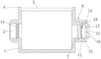
图2为本实用新型的剖视图。Figure 2 is a cross-sectional view of the utility model.
图中:1机箱、2排气口、3端盖、4螺钉、5插板、6插槽、7密封板、8把手、9矩形槽、10伸缩槽、11进气台、12进气口、13转柄、14第一滤网、15第二滤网、16散热风机、17毛刷条、18连杆。In the picture: 1 chassis, 2 exhaust ports, 3 end covers, 4 screws, 5 plug-in boards, 6 slots, 7 sealing plates, 8 handles, 9 rectangular slots, 10 expansion slots, 11 air inlets, 12 air inlets , 13 handle, 14 first filter, 15 second filter, 16 cooling fan, 17 brush strip, 18 connecting rod.
具体实施方式Detailed ways
下面将结合本实用新型实施例中的附图,对本实用新型实施例中的技术方案进行清楚、完整地描述,显然,所描述的实施例仅仅是本实用新型一部分实施例,而不是全部的实施例。基于本实用新型中的实施例,本领域普通技术人员在没有做出创造性劳动前提下所获得的所有其他实施例,都属于本实用新型保护的范围。The technical solutions in the embodiments of the present utility model will be clearly and completely described below with reference to the accompanying drawings in the embodiments of the present utility model. Obviously, the described embodiments are only a part of the embodiments of the present utility model, rather than all the implementations. example. Based on the embodiments of the present invention, all other embodiments obtained by those of ordinary skill in the art without creative work fall within the protection scope of the present invention.
请参阅图1至图2,本实用新型提供一种技术方案:Please refer to FIG. 1 to FIG. 2, the utility model provides a technical solution:
一种具有自除尘功能的计算机机箱,包括机箱1,机箱1的上端设置有端盖3,端盖3密封覆盖在机箱1的上端开口,端盖3通过螺钉4固定在机箱1的上端面,利用端盖3实现机箱1上端的密封。A computer case with a self-dusting function, comprising a
机箱1的右端面固定焊接有进气台11,进气台11的右侧设置有进气口12,进气口12的内腔左端设置有散热风机16,进气口12的左侧连通机箱1的内腔,机箱1的左端面设置有排气口2,利用散热风机16将外界气流从进气口12吸入机箱1的内腔,然后通过风冷的方式将机箱1内部的热量带走,并从排气口2排出。The right end face of the
散热风机16的左侧设置有第二滤网15,排气口2的右侧设置有第一滤网14,排气口2的右侧连通机箱1的内腔,第一滤网14完全覆盖排气口2,利用第二滤网15对进入的气流进行过滤,使得灰尘落在第二滤网15上。The left side of the
进气台11的前端面固定焊接有插板5,插板5的内腔设置有上下对称的一对插槽6,插槽6的内腔外形与密封板7的外轮廓相同,利用插槽6实现对密封板7的备用放置。The front end surface of the air inlet table 11 is fixedly welded with a plug-in
进气台11的左侧开设有矩形槽9,矩形槽9的内腔滑动插接有密封板7,密封板7的上端设置有把手8,利用矩形槽9与密封板7的配合实现对机箱1右侧的密封。The left side of the air inlet table 11 is provided with a
第二滤网15的右侧上端设置有毛刷条17,毛刷条17的长度与第二滤网15的长度相同,毛刷条17的左端面与第二滤网15的端面贴合,利用毛刷条17实现对第二滤网15的清理。The upper right end of the
毛刷条17的上端垂直焊接有连杆18,进气台11的上端面设置有伸缩槽10,连杆18的上端延伸至伸缩槽10内,连杆18的上端转动安装有转柄13,转柄13通过转轴转动在连杆18的上端面,利用转柄13和连杆18的配合,实现对毛刷条17的固定,当转柄13和连杆18转动重合时,通过转柄13上下移动,带动毛刷条17上下清理第二滤网15,当转柄13与连杆18转动垂直时,通过连杆18的位置实现毛刷条17的位置固定。The upper end of the
工作原理:首先利用端盖3实现机箱1上端的密封,利用散热风机16将外界气流从进气口12吸入机箱1的内腔,然后通过风冷的方式将机箱1内部的热量带走,并从排气口2排出,利用第二滤网15对进入的气流进行过滤,使得灰尘落在第二滤网15上,利用矩形槽9与密封板7的配合实现对机箱1右侧的密封。Working principle: First, use the
当需要清理时,转柄13和连杆18转动重合,通过转柄13上下移动,使得连杆18带动毛刷条17上下清理第二滤网15。When cleaning is required, the
当正常使用时,矩形槽9通过橡胶塞密封,转柄13与连杆18转动垂直,从而通过连杆18的位置实现毛刷条17的位置固定,此时密封板7插接在插板5的内部插槽6中。In normal use, the
尽管已经示出和描述了本实用新型的实施例,对于本领域的普通技术人员而言,可以理解在不脱离本实用新型的原理和精神的情况下可以对这些实施例进行多种变化、修改、替换和变型,本实用新型的范围由所附权利要求及其等同物限定。Although the embodiments of the present invention have been shown and described, it will be understood by those skilled in the art that various changes and modifications can be made to these embodiments without departing from the principles and spirit of the present invention , alternatives and modifications, the scope of the present invention is defined by the appended claims and their equivalents.
Claims (5)
Priority Applications (1)
| Application Number | Priority Date | Filing Date | Title |
|---|---|---|---|
| CN201921612750.9UCN210142300U (en) | 2019-09-26 | 2019-09-26 | A computer case with self-dusting function |
Applications Claiming Priority (1)
| Application Number | Priority Date | Filing Date | Title |
|---|---|---|---|
| CN201921612750.9UCN210142300U (en) | 2019-09-26 | 2019-09-26 | A computer case with self-dusting function |
Publications (1)
| Publication Number | Publication Date |
|---|---|
| CN210142300Utrue CN210142300U (en) | 2020-03-13 |
Family
ID=69736496
Family Applications (1)
| Application Number | Title | Priority Date | Filing Date |
|---|---|---|---|
| CN201921612750.9UExpired - Fee RelatedCN210142300U (en) | 2019-09-26 | 2019-09-26 | A computer case with self-dusting function |
Country Status (1)
| Country | Link |
|---|---|
| CN (1) | CN210142300U (en) |
Cited By (1)
| Publication number | Priority date | Publication date | Assignee | Title |
|---|---|---|---|---|
| CN112181076A (en)* | 2020-09-25 | 2021-01-05 | 杭州户联软件开发有限公司 | Computer case with self-dust removal function |
- 2019
- 2019-09-26CNCN201921612750.9Upatent/CN210142300U/ennot_activeExpired - Fee Related
Cited By (2)
| Publication number | Priority date | Publication date | Assignee | Title |
|---|---|---|---|---|
| CN112181076A (en)* | 2020-09-25 | 2021-01-05 | 杭州户联软件开发有限公司 | Computer case with self-dust removal function |
| CN112181076B (en)* | 2020-09-25 | 2024-02-06 | 宁波市宏雍智能科技有限公司 | Computer case with self-dedusting function |
Similar Documents
| Publication | Publication Date | Title |
|---|---|---|
| CN207704349U (en) | A kind of computer cabinet with automatic ash removing function | |
| CN212068188U (en) | A dedusting device for construction engineering | |
| WO2022027856A1 (en) | Air filter with self-sealing device | |
| CN109144194A (en) | A kind of computer cabinet with self-cleaning function | |
| CN217715394U (en) | Air outlet structure of air conditioner panel | |
| CN112058798A (en) | A device for automatically cleaning dust installed in a computer host | |
| CN210142300U (en) | A computer case with self-dusting function | |
| CN206421301U (en) | A computer case prototype | |
| CN115576400A (en) | Heat dissipation device with dust removal function for computer hardware | |
| CN208495225U (en) | A kind of computer host dust-extraction unit | |
| CN210895242U (en) | A computer host box with a vacuuming function | |
| CN110883013A (en) | Cleaning mechanism for cooling net of computer | |
| CN209486563U (en) | A kind of computer cabinet with self-cleaning function | |
| CN211854417U (en) | Air conditioner with self-cleaning function | |
| CN210931164U (en) | Dust collecting box for dust collector | |
| CN210776445U (en) | A dust-proof computer case | |
| CN221670071U (en) | Wireless gateway with dustproof construction | |
| CN118102644B (en) | A dustproof 5G outdoor communication cabinet | |
| CN215117356U (en) | Computer machine case with dust removal mechanism | |
| CN218011664U (en) | filter dust remover | |
| CN111352487A (en) | Computer machine case with inside dustproof construction | |
| CN221901253U (en) | A ventilation device for a communication base station | |
| CN220771292U (en) | Fire control engineering is with preventing fume extractor | |
| CN220582717U (en) | Factory building ventilation dust collector | |
| CN220760356U (en) | Computer machine case cleaning device |
Legal Events
| Date | Code | Title | Description |
|---|---|---|---|
| GR01 | Patent grant | ||
| GR01 | Patent grant | ||
| CF01 | Termination of patent right due to non-payment of annual fee | Granted publication date:20200313 | |
| CF01 | Termination of patent right due to non-payment of annual fee |