CN210131076U - An upper limb rehabilitation robot with easy height adjustment - Google Patents
An upper limb rehabilitation robot with easy height adjustmentDownload PDFInfo
- Publication number
- CN210131076U CN210131076UCN201920592736.0UCN201920592736UCN210131076UCN 210131076 UCN210131076 UCN 210131076UCN 201920592736 UCN201920592736 UCN 201920592736UCN 210131076 UCN210131076 UCN 210131076U
- Authority
- CN
- China
- Prior art keywords
- fixedly installed
- height
- upper limb
- rehabilitation robot
- limb rehabilitation
- Prior art date
- Legal status (The legal status is an assumption and is not a legal conclusion. Google has not performed a legal analysis and makes no representation as to the accuracy of the status listed.)
- Expired - Fee Related
Links
Images


Landscapes
- Rehabilitation Tools (AREA)
Abstract
Description
Translated fromChinese技术领域technical field
本实用新型涉及医疗器械技术领域,具体为一种便于调整高度的上肢康复机器人。The utility model relates to the technical field of medical devices, in particular to an upper limb rehabilitation robot which is convenient for height adjustment.
背景技术Background technique
随着社会老龄化日益严重,脑卒患者人数也不断提升,因此急需将更加先进的技术引入到康复治疗领域,上肢康复机器人是机器人技术在上肢康复医学应用的产物,能够便于患者进行一系列的康复治疗,传统的上肢康复机器人由于在实际使用过程中缺少调高的功能,进而导致不同身高的患者在使用康复机器人时均会产生不适感,进而降低了康复机器人的实际康复治疗效果,且不利于康复机器人的推广使用。With the increasing aging of society and the increasing number of stroke patients, it is urgent to introduce more advanced technologies into the field of rehabilitation therapy. The upper limb rehabilitation robot is the product of the application of robotic technology in upper limb rehabilitation medicine, which can facilitate patients to carry out a series of Rehabilitation treatment, the traditional upper limb rehabilitation robot lacks the function of height adjustment in the actual use process, which leads to discomfort when using the rehabilitation robot for patients of different heights, thereby reducing the actual rehabilitation treatment effect of the rehabilitation robot. It is conducive to the promotion and use of rehabilitation robots.
实用新型内容Utility model content
本实用新型提供一种便于调整高度的上肢康复机器人,可以有效解决上述背景技术中提出传统的上肢康复机器人由于在实际使用过程中缺少调高的功能,进而导致不同身高的患者在使用康复机器人时均会产生不适感,进而降低了康复机器人的实际康复治疗效果,且不利于康复机器人的推广使用的问题。The utility model provides an upper limb rehabilitation robot which is easy to adjust the height, which can effectively solve the problem that the traditional upper limb rehabilitation robot lacks the function of height adjustment in the actual use process proposed in the above-mentioned background technology, which leads to patients of different heights when using the rehabilitation robot. Both will cause discomfort, thereby reducing the actual rehabilitation treatment effect of the rehabilitation robot, and is not conducive to the promotion and use of the rehabilitation robot.
为实现上述目的,本实用新型提供如下技术方案:一种便于调整高度的上肢康复机器人,包括底板,所述底板底端四角处均通过移动支架固定安装有移动轮,所述底板顶部一侧固定安装有储物箱,所述储物箱顶部固定安装有顶板,所述顶板顶端中部固定安装有连接座,所述连接座顶端固定焊接有调高气缸,所述调高气缸一侧边部活动连接有调节手柄,所述调高气缸顶端固定安装有诊疗座椅,所述诊疗座椅一侧边端活动连接有靠背,所述底板顶部另一侧与储物箱对应位置处固定焊接有套筒,所述套筒内部嵌入活动连接有伸缩柱;In order to achieve the above purpose, the present utility model provides the following technical solutions: an upper limb rehabilitation robot that is easy to adjust the height, comprising a bottom plate, the four corners of the bottom end of the bottom plate are fixedly installed with moving wheels through moving brackets, and one side of the top of the bottom plate is fixed. A storage box is installed, a top plate is fixedly installed on the top of the storage box, a connecting seat is fixedly installed in the middle of the top end of the top plate, and a height-adjusting cylinder is fixedly welded at the top of the connecting seat, and one side of the height-adjusting cylinder is movable. An adjustment handle is connected, a diagnosis and treatment seat is fixedly installed at the top of the height-adjusting cylinder, a backrest is movably connected to one side of the diagnosis and treatment seat, and a sleeve is fixedly welded at the corresponding position of the storage box on the other side of the top of the bottom plate. The sleeve is embedded and movably connected with a telescopic column inside the sleeve;
所述伸缩柱顶端固定安装有控制箱,所述控制箱顶端中部开设有活动滑槽,所述活动滑槽内部一侧嵌入滑动连接有连接滑座,所述连接滑座顶部一侧下方位置处活动连接有活动机械臂;A control box is fixedly installed at the top of the telescopic column, a movable chute is provided in the middle of the top of the control box, and a connecting slide is embedded and slidably connected on one side of the inner side of the movable chute. The movable connection has a movable mechanical arm;
所述活动机械臂一侧顶部固定安装有U型夹持条,所述U型夹持条一侧顶端固定安装有契合插块,所述U型夹持条另一侧顶端与契合插块对应位置处固定连接有连接插头,所述U型夹持条内侧顶面中部固定粘结有柔性橡胶垫板,所述活动机械臂顶面一侧端部固定安装有握把。A U-shaped clamping strip is fixedly installed on the top of one side of the movable mechanical arm, a fitting insert block is fixedly installed on the top of one side of the U-shaped clamping strip, and the top of the other side of the U-shaped clamping strip corresponds to the fitting insert block. A connection plug is fixedly connected at the position, a flexible rubber pad is fixedly bonded to the middle of the inner top surface of the U-shaped clamping strip, and a handle is fixedly installed at one end of the top surface of the movable mechanical arm.
优选的,所述诊疗座椅顶面和靠背内侧表面均固定粘结有柔性橡胶垫。Preferably, flexible rubber pads are fixedly bonded to the top surface of the diagnosis and treatment seat and the inner surface of the backrest.
优选的,所述U型夹持条为一种软性橡胶材质的构件,所述U型夹持条底部与活动机械臂之间通过连接胶板固定连接。Preferably, the U-shaped clamping strip is a member of a soft rubber material, and the bottom of the U-shaped clamping strip and the movable mechanical arm are fixedly connected by a connecting rubber plate.
优选的,所述契合插块内部均开设有契合槽,所述连接插头的外径与契合槽的内径相等。Preferably, each of the fitting plugs is provided with a fitting groove, and the outer diameter of the connecting plug is equal to the inner diameter of the fitting groove.
所述储物箱内部外侧嵌入安装有置物抽屉,所述置物抽屉两侧位于储物箱内侧边部位置处均开设有导向滑槽,所述置物抽屉两侧边端与导向滑槽对应位置处均安装有导向滑块。A storage drawer is embedded and installed on the inner and outer sides of the storage box, and guide chutes are provided on both sides of the storage drawer at the inner side of the storage box, and the two sides of the storage drawer are corresponding to the guide chutes. Guide sliders are installed everywhere.
优选的,所述储物箱内部开设有容置槽,所述置物抽屉嵌于容置槽内,且导向滑槽均开设于容置槽的两侧边端。Preferably, an accommodating groove is provided inside the storage box, the storage drawer is embedded in the accommodating groove, and the guide chutes are both opened on both side edges of the accommodating groove.
与现有技术相比,本实用新型的有益效果:本实用新型结构科学合理,使用安全方便:Compared with the prior art, the beneficial effects of the present utility model: the utility model has a scientific and reasonable structure, and is safe and convenient to use:
1、通过连接座、调高气缸和调节手柄便于对诊疗座椅和靠背的高度进行调节,进而使患者在坐立治疗过程中更加舒适,套筒和伸缩柱便于对控制箱和活动机械臂的高度进行调节,进而使患者在治疗过程中具备更高的治疗效果,通过以上的调高,能够使装置适用于不同身高的患者,进而提高装置治疗的范围和治疗的效率。1. It is convenient to adjust the height of the diagnosis and treatment seat and backrest by connecting the seat, the height adjusting cylinder and the adjusting handle, so as to make the patient more comfortable during the sitting and standing treatment. The sleeve and telescopic column are convenient for the control box and the movable mechanical arm. The height is adjusted, so that the patient has a higher therapeutic effect during the treatment process. Through the above height adjustment, the device can be adapted to patients of different heights, thereby improving the treatment range and treatment efficiency of the device.
2、通过U型夹持条、契合插块、连接插头和柔性橡胶垫板能够以柔性橡胶的材质与患者手臂之间进行接触,在保证U型夹持条与患者手臂之间稳固性的同时,防止U型夹持条对患者手臂造成勒迫感,进而进一步提高患者治疗过程中的舒适性。2. Through the U-shaped clamping strip, the fitting plug, the connecting plug and the flexible rubber pad, the flexible rubber material can be used to contact the patient's arm, while ensuring the stability between the U-shaped clamping strip and the patient's arm , to prevent the U-shaped clamping strip from causing a sense of pressure on the patient's arm, thereby further improving the comfort of the patient during the treatment process.
3、通过储物箱、置物抽屉、导向滑槽和导向滑块能够在装置的底部为患者和医师提供一个储物的空间,进而便于将患者或医师的随身物品和辅助治疗器具等进行存放,进而使人们在取拿物品时更加方便。3. The storage box, storage drawer, guide chute and guide slider can provide a storage space for the patient and the doctor at the bottom of the device, so as to facilitate the storage of the patient's or doctor's personal belongings and auxiliary treatment equipment, etc. This makes it more convenient for people to pick up and take items.
附图说明Description of drawings
附图用来提供对本实用新型的进一步理解,并且构成说明书的一部分,与本实用新型的实施例一起用于解释本实用新型,并不构成对本实用新型的限制。The accompanying drawings are used to provide a further understanding of the present invention, and constitute a part of the specification, and are used to explain the present invention together with the embodiments of the present invention, and do not constitute a limitation to the present invention.
在附图中:In the attached image:
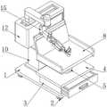
图1是本实用新型的结构示意图;Fig. 1 is the structural representation of the present utility model;
图2是本实用新型U型夹持条的安装结构示意图;2 is a schematic diagram of the installation structure of the U-shaped clamping strip of the present invention;
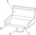
图3是本实用新型调高气缸的安装结构示意图;3 is a schematic diagram of the installation structure of the height-adjusting cylinder of the present invention;
图4是本实用新型置物抽屉的安装结构示意图;4 is a schematic diagram of the installation structure of the storage drawer of the present invention;
图5是本实用新型伸缩柱与套筒的连接结构示意图;5 is a schematic diagram of the connection structure of the telescopic column and the sleeve of the present invention;
图中标号:1、底板;2、移动轮;3、储物箱;4、顶板;5、连接座;6、调高气缸;7、调节手柄;8、诊疗座椅;9、靠背;10、套筒;11、伸缩柱;12、控制箱;13、活动滑槽;14、连接滑座;15、活动机械臂;16、U型夹持条;17、契合插块;18、连接插头;19、柔性橡胶垫板;20、握把;21、置物抽屉;22、导向滑槽;23、导向滑块。Labels in the figure: 1. Bottom plate; 2. Moving wheel; 3. Storage box; 4. Top plate; 5. Connecting seat; 6. Height-adjusting cylinder; 7. Adjusting handle; , sleeve; 11, telescopic column; 12, control box; 13, movable chute; 14, connecting slide; 15, movable mechanical arm; 16, U-shaped clamping strip; 17, fitting plug; 18, connecting plug ; 19, flexible rubber pad; 20, handle; 21, storage drawer; 22, guide chute; 23, guide slider.
具体实施方式Detailed ways
以下结合附图对本实用新型的优选实施例进行说明,应当理解,此处所描述的优选实施例仅用于说明和解释本实用新型,并不用于限定本实用新型。The preferred embodiments of the present utility model will be described below with reference to the accompanying drawings. It should be understood that the preferred embodiments described herein are only used to illustrate and explain the present utility model, but not to limit the present utility model.
实施例:如图1-5所示,本实用新型提供一种技术方案,一种便于调整高度的上肢康复机器人,包括底板1,底板1底端四角处均通过移动支架固定安装有移动轮2,底板1顶部一侧固定安装有储物箱3,储物箱3顶部固定安装有顶板4,顶板4顶端中部固定安装有连接座5,连接座5顶端固定焊接有调高气缸6,调高气缸6一侧边部活动连接有调节手柄7,调高气缸6顶端固定安装有诊疗座椅8,诊疗座椅8一侧边端活动连接有靠背9,诊疗座椅8顶面和靠背9内侧表面均固定粘结有柔性橡胶垫,使患者坐立在诊疗座椅8和靠背9的内侧时更加舒适,底板1顶部另一侧与储物箱3对应位置处固定焊接有套筒10,套筒10内部嵌入活动连接有伸缩柱11。Embodiment: As shown in Figures 1-5, the present utility model provides a technical solution, an upper limb rehabilitation robot that is easy to adjust the height, including a
伸缩柱11顶端固定安装有控制箱12,控制箱12顶端中部开设有活动滑槽13,活动滑槽13内部一侧嵌入滑动连接有连接滑座14,连接滑座14顶部一侧下方位置处活动连接有活动机械臂15。A
活动机械臂15一侧顶部固定安装有U型夹持条16,U型夹持条16为一种软性橡胶材质的构件,U型夹持条16底部与活动机械臂15之间通过连接胶板固定连接,提高U型夹持条16与患者手臂之间夹持的紧固性,同时便于U型夹持条16与活动机械臂15之间的固定连接,U型夹持条16一侧顶端固定安装有契合插块17,U型夹持条16另一侧顶端与契合插块17对应位置处固定连接有连接插头18,契合插块17内部均开设有契合槽,连接插头18的外径与契合槽的内径相等,便于契合插块17与连接插头18之间进行紧密连接,同时便于将U型夹持条16与患者手臂之间进行固定,U型夹持条16内侧顶面中部固定粘结有柔性橡胶垫板19,活动机械臂15顶面一侧端部固定安装有握把20。A U-shaped
储物箱3内部外侧嵌入安装有置物抽屉21,置物抽屉21两侧位于储物箱3内侧边部位置处均开设有导向滑槽22,储物箱3内部开设有容置槽,置物抽屉21嵌于容置槽内,且导向滑槽22均开设于容置槽的两侧边端,便于置物抽屉21与储物箱3之间的滑动连接,置物抽屉21两侧边端与导向滑槽22对应位置处均安装有导向滑块23。A
本实用新型的工作原理及使用流程:该便于调整高度的上肢康复机器人在实际使用过程中,首先利用底板1底端的移动轮2来将底板1移动至治疗区域,接着将待治疗的患者扶上诊疗座椅8,且使患者的背部紧靠靠背9,在患者坐立于诊疗座椅8上时,此时依据待治疗患者的身高来调整诊疗座椅8的高度,在调节过程中,利用调节手柄7的上下移动来对带动调高气缸6的升降,进而来对诊疗座椅8的高度进行调整,以此使患者在坐立治疗过程中更加舒适,在诊疗座椅8的高度调节后,此时再次依据患者的身高来调整控制箱12和活动机械臂15的位置高度,在调节过程中,利用套筒10与其内部伸缩柱11之间的导向滑动来调节控制箱12的高度,进而使患者的手臂与活动机械臂15之间不产生较大的间距,进而为后续患者上肢的康复治疗做好准备,综合以上的调高处理后,不均使患者在治疗过程中更加舒适,同时能够极大程度上提高患者上肢康复的效果;The working principle and use process of the present utility model: in the actual use process of the upper limb rehabilitation robot, which is easy to adjust the height, firstly, the
在诊疗座椅8和控制箱12均调高后,此时将患者的手掌紧握在握把20上,并将患者的手臂搭接在U型夹持条16的内侧,且使患者手臂的底端与柔性橡胶垫板19之间进行接触,紧接着利用契合插块17与连接插头18来将U型夹持条16与患者手臂之间进行锁紧固定,进而使活动机械臂15在活动过程中能够带动患者手臂进行移动,该固定方式不仅快速便捷,同时避免了患者手臂与U型夹持条16之间因夹持力度过大,导致患者手臂产生勒迫感,进一步提高了患者治疗过程中的舒适性;After the diagnosis and
在患者手臂被固定后,此时将控制箱12接电,利用控制箱12内部的控制元件来控制活动机械臂15的摆动,以此利用活动机械臂15的摆动来匀速的带动患者的手臂进行移动,进而对患者的上肢进行导向性的康复治疗,该技术为现有公开技术,在此不做详述;After the patient's arm is fixed, the
而在实际康复治疗过程中,通过导向滑块23与导向滑槽22之间的导向滑动将置物抽屉21从储物箱3内抽出,然后再将患者或医师的随身物品和辅助治疗器具等存放在置物抽屉21内,进而使人们在取拿物品时更加方便,提高了使用的便捷性。In the actual rehabilitation treatment process, the
最后应说明的是:以上所述仅为本实用新型的优选实例而已,并不用于限制本实用新型,尽管参照前述实施例对本实用新型进行了详细的说明,对于本领域的技术人员来说,其依然可以对前述各实施例所记载的技术方案进行修改,或者对其中部分技术特征进行等同替换。凡在本实用新型的精神和原则之内,所作的任何修改、等同替换、改进等,均应包含在本实用新型的保护范围之内。Finally, it should be noted that the above is only a preferred example of the present utility model, and is not intended to limit the present utility model. Although the present utility model has been described in detail with reference to the foregoing embodiments, for those skilled in the art, It is still possible to modify the technical solutions described in the foregoing embodiments, or perform equivalent replacements to some of the technical features. Any modification, equivalent replacement, improvement, etc. made within the spirit and principle of the present invention shall be included in the protection scope of the present invention.
Claims (6)
Translated fromChinesePriority Applications (1)
| Application Number | Priority Date | Filing Date | Title |
|---|---|---|---|
| CN201920592736.0UCN210131076U (en) | 2019-04-28 | 2019-04-28 | An upper limb rehabilitation robot with easy height adjustment |
Applications Claiming Priority (1)
| Application Number | Priority Date | Filing Date | Title |
|---|---|---|---|
| CN201920592736.0UCN210131076U (en) | 2019-04-28 | 2019-04-28 | An upper limb rehabilitation robot with easy height adjustment |
Publications (1)
| Publication Number | Publication Date |
|---|---|
| CN210131076Utrue CN210131076U (en) | 2020-03-10 |
Family
ID=69704015
Family Applications (1)
| Application Number | Title | Priority Date | Filing Date |
|---|---|---|---|
| CN201920592736.0UExpired - Fee RelatedCN210131076U (en) | 2019-04-28 | 2019-04-28 | An upper limb rehabilitation robot with easy height adjustment |
Country Status (1)
| Country | Link |
|---|---|
| CN (1) | CN210131076U (en) |
Cited By (2)
| Publication number | Priority date | Publication date | Assignee | Title |
|---|---|---|---|---|
| CN111513992A (en)* | 2020-06-02 | 2020-08-11 | 辽宁科技大学 | Physical therapy device is tempered to recovered arm |
| CN112245225A (en)* | 2020-10-23 | 2021-01-22 | 永康中科千喜医疗科技有限公司 | Adjustable rehabilitation chair |
- 2019
- 2019-04-28CNCN201920592736.0Upatent/CN210131076U/ennot_activeExpired - Fee Related
Cited By (2)
| Publication number | Priority date | Publication date | Assignee | Title |
|---|---|---|---|---|
| CN111513992A (en)* | 2020-06-02 | 2020-08-11 | 辽宁科技大学 | Physical therapy device is tempered to recovered arm |
| CN112245225A (en)* | 2020-10-23 | 2021-01-22 | 永康中科千喜医疗科技有限公司 | Adjustable rehabilitation chair |
Similar Documents
| Publication | Publication Date | Title |
|---|---|---|
| CN210131076U (en) | An upper limb rehabilitation robot with easy height adjustment | |
| CN107296719A (en) | A kind of five-freedom degree dermaskeleton type upper limb rehabilitation robot | |
| CN107802393A (en) | Orthopedic rehabilitation nursing traction bracket | |
| CN109875821B (en) | A kind of auxiliary recovery equipment for lumbar disc herniation | |
| CN211511843U (en) | Head support of CT examination bed | |
| CN107334620B (en) | One kind being used for patient's waist adjuvant therapy device | |
| CN213465864U (en) | General type thyroid surgery position pad | |
| CN209122567U (en) | A kind of massage bed with Telescopic | |
| CN209519023U (en) | Adjustable height posture pad | |
| CN207384409U (en) | Multi-functional auxiliary turn-over bed for patient pad | |
| CN211188206U (en) | Rheumatism immunity branch of academic or vocational study is with medicine fumigation treatment device | |
| CN207384441U (en) | A kind of angiocarpy insertion ray protection platform | |
| CN220046446U (en) | Neurosurgery lumbar vertebrae nerve resumes equipment | |
| CN209004477U (en) | A kind of auxiliary lower limb rehabilitation rehabilitation medical bed | |
| CN209253541U (en) | A massage robot for leg rehabilitation care | |
| CN221691689U (en) | Novel air cushion bed for orthopedic nursing | |
| CN216021790U (en) | Supplementary nursing ware that stands up of bed patient | |
| CN216318734U (en) | An improved scraping stool | |
| CN106214422A (en) | Orthopeadic Surgery shoulder rehabilitation therapy equipment | |
| CN219538746U (en) | Leg support device on bed | |
| CN208130121U (en) | For vertebra postoperative patient prostrate support device | |
| CN221470213U (en) | Patient lifting device that is easy to fix | |
| CN221831013U (en) | Early activity training chair for mechanical ventilation patient | |
| CN222383449U (en) | A cervical spine medical device | |
| CN221106317U (en) | A lower limb rehabilitation device for stroke paralysis patients |
Legal Events
| Date | Code | Title | Description |
|---|---|---|---|
| GR01 | Patent grant | ||
| GR01 | Patent grant | ||
| CF01 | Termination of patent right due to non-payment of annual fee | ||
| CF01 | Termination of patent right due to non-payment of annual fee | Granted publication date:20200310 |