CN210108389U - An onshore simulation experiment device for submarine cable temperature stress - Google Patents
An onshore simulation experiment device for submarine cable temperature stressDownload PDFInfo
- Publication number
- CN210108389U CN210108389UCN201921010752.0UCN201921010752UCN210108389UCN 210108389 UCN210108389 UCN 210108389UCN 201921010752 UCN201921010752 UCN 201921010752UCN 210108389 UCN210108389 UCN 210108389U
- Authority
- CN
- China
- Prior art keywords
- optical fiber
- temperature
- strain
- displacement platform
- submarine cable
- Prior art date
- Legal status (The legal status is an assumption and is not a legal conclusion. Google has not performed a legal analysis and makes no representation as to the accuracy of the status listed.)
- Active
Links
- 238000004088simulationMethods0.000titleclaimsabstractdescription23
- 239000013307optical fiberSubstances0.000claimsabstractdescription97
- 238000006073displacement reactionMethods0.000claimsabstractdescription35
- 238000012360testing methodMethods0.000claimsdescription16
- 230000003287optical effectEffects0.000claimsdescription5
- 238000005259measurementMethods0.000claimsdescription4
- 239000000835fiberSubstances0.000abstractdescription29
- 238000012544monitoring processMethods0.000abstractdescription9
- 230000008859changeEffects0.000abstractdescription6
- 238000009434installationMethods0.000abstractdescription2
- 238000010586diagramMethods0.000description6
- 238000002474experimental methodMethods0.000description6
- 230000006872improvementEffects0.000description3
- 238000000034methodMethods0.000description3
- 230000000694effectsEffects0.000description2
- 230000036541healthEffects0.000description2
- 230000006855networkingEffects0.000description2
- 238000012545processingMethods0.000description2
- 230000002159abnormal effectEffects0.000description1
- 238000009360aquacultureMethods0.000description1
- 244000144974aquacultureSpecies0.000description1
- 230000009286beneficial effectEffects0.000description1
- 230000007812deficiencyEffects0.000description1
- 238000001514detection methodMethods0.000description1
- 238000011161developmentMethods0.000description1
- 238000009413insulationMethods0.000description1
- 238000009421internal insulationMethods0.000description1
- 230000008569processEffects0.000description1
- 238000011160researchMethods0.000description1
- 238000012502risk assessmentMethods0.000description1
- 230000006641stabilisationEffects0.000description1
- 238000011105stabilizationMethods0.000description1
- 238000012795verificationMethods0.000description1
Images
Landscapes
- Measuring Temperature Or Quantity Of Heat (AREA)
Abstract
Description
Translated fromChinese技术领域technical field
本实用新型属于电缆状态监测技术领域,具体涉及一种海底电缆温度应力岸上模拟实验装置。The utility model belongs to the technical field of cable state monitoring, in particular to an onshore simulation experiment device for temperature stress of submarine cables.
背景技术Background technique
无论海底电缆遭受外力破坏而损坏,还是由于其内部绝缘或其他原因出现异常时,只能通过对海底电缆本体的在线监测才能及时了解。目前海南联网系统海底电缆本体仅有的在线监测方式为温度在线监测,手段较为单一,且故障频发,可用性不佳。南网科研院在2013年研究实施的海底电缆绝缘在线监测中的局部放电也仅限于监测两侧终端处。因此对于三相31km长的海底电缆本体,在运行过程中,现阶段无法准确掌握其运行状态及健康水平,对于设备的风险评估也会出现较大的误差。Whether the submarine cable is damaged by external force or abnormal due to its internal insulation or other reasons, it can only be understood in time through the online monitoring of the submarine cable itself. At present, the only online monitoring method of the submarine cable body of the Hainan networking system is online temperature monitoring, which is relatively simple, and has frequent failures and poor usability. The partial discharge in the online monitoring of submarine cable insulation researched and implemented by China Southern Power Research Institute in 2013 is also limited to monitoring the terminals on both sides. Therefore, for the three-phase 31km long submarine cable body, during the operation process, it is impossible to accurately grasp its operation status and health level at this stage, and there will be large errors in the risk assessment of the equipment.
目前,对于海南联网系统三相31km的海底电缆,其温度、应力的运行状态、健康水平,目前掌握情况还非常有限,故利用光纤传感原理,研究如何依靠海底电缆本体捆绑的光缆实现海底电缆温度、应力本体运行状态的在线监测至关重要由于海缆一般比较复杂,要进行海缆本体实验比较困难,而且成本比较高。海洋开发活动的日益增加,海域内的养殖、渔网、船锚等对海缆运行的影响不容忽视,海缆机械故障时有发生,此类故障一般都能体现为海底电缆应变的变化。因此,现有的测试装置不能针对海底电缆岸上模拟实验测量是本领域技术人员需要解决的技术问题。At present, for the three-phase 31km submarine cable in Hainan's networking system, the operating state of temperature, stress, and health level are still very limited. Therefore, using the principle of optical fiber sensing, we study how to rely on the optical cable bundled with the submarine cable body to realize the submarine cable. On-line monitoring of the operating state of temperature and stress is very important. Because submarine cables are generally complex, it is difficult and costly to conduct submarine cable body experiments. With the increasing number of marine development activities, the influence of aquaculture, fishing nets, and anchors in the sea area on the operation of submarine cables cannot be ignored. Mechanical failures of submarine cables occur from time to time. Therefore, it is a technical problem that those skilled in the art need to solve that the existing test device cannot measure the submarine cable onshore simulation experiment.
实用新型内容Utility model content
本实用新型的目的在于针对上述现有技术的不足,提供了一种海底电缆温度应力岸上模拟实验装置。The purpose of the utility model is to provide an onshore simulation experiment device for the temperature stress of submarine cables in view of the deficiencies of the above-mentioned prior art.
本实用新型采用如下技术方案来实现的:The utility model adopts the following technical solutions to realize:
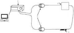
一种海底电缆温度应力岸上模拟实验装置,包括光纤盘,光纤温度应变分析仪,恒温烘箱,以及高精度位移平台;其中,An onshore simulation experiment device for submarine cable temperature stress, comprising an optical fiber disk, an optical fiber temperature strain analyzer, a constant temperature oven, and a high-precision displacement platform; wherein,
测量时,待测光纤盘中的光纤的一端与光纤温度应变分析仪发射端相连,另一端依次与放入恒温烘箱中的光纤和固定在高精度位移平台上的光纤相连,最后与光纤温度应变分析仪接收端相连,形成另一条光通路;通过改变接入光纤盘长度来模拟实际海缆运行距离;利用放入恒温烘箱中的光纤和浴槽外的光纤进行光纤温度应变分析仪的空间分布率测试以及温度故障模拟;利用高精度位移平台改变光纤应变大小来模拟应变故障;光纤温度应变分析仪用于采集不同时刻的不同位置的布里渊位移频移。During measurement, one end of the optical fiber in the optical fiber tray to be measured is connected to the transmitting end of the optical fiber temperature strain analyzer, and the other end is connected to the optical fiber placed in the constant temperature oven and the optical fiber fixed on the high-precision displacement platform in turn, and finally to the optical fiber temperature strain. The receiving end of the analyzer is connected to form another optical path; the actual running distance of the submarine cable is simulated by changing the length of the access optical fiber disk; the spatial distribution rate of the optical fiber temperature strain analyzer is carried out by using the optical fiber placed in the constant temperature oven and the optical fiber outside the bath. Testing and temperature fault simulation; using a high-precision displacement platform to change the size of the optical fiber strain to simulate the strain fault; the optical fiber temperature strain analyzer is used to collect the Brillouin displacement frequency shift at different positions at different times.
本实用新型进一步的改进在于,待测光纤盘能够根据实际海缆运行情况的长度进行模拟,而且能够在光纤盘的前后不同位置进行温度应变故障模拟。The further improvement of the utility model lies in that the optical fiber reel to be tested can be simulated according to the length of the actual submarine cable operation, and the temperature strain fault simulation can be performed at different positions before and after the optical fiber reel.
本实用新型进一步的改进在于,通过放置在恒温烘箱内外不同长度的光纤,验证当前设备经过光纤盘长度后的空间分布率、温度分辨率以及温度故障。The further improvement of the utility model lies in that the spatial distribution rate, temperature resolution and temperature failure of the current equipment after passing through the length of the optical fiber disk are verified by placing optical fibers of different lengths inside and outside the constant temperature oven.
本实用新型进一步的改进在于,通过固定在高精度位移平台上的光纤,控制高精度位移平台不同的位移,来实现经过光纤盘长度后的应变分辨率以及应变故障。The further improvement of the utility model is that, through the optical fiber fixed on the high-precision displacement platform, the different displacements of the high-precision displacement platform are controlled to realize the strain resolution and strain failure after the length of the optical fiber disk.
本实用新型具有如下有益的技术效果:The utility model has the following beneficial technical effects:
本实用新型提供的一种海底电缆温度应力岸上模拟实验装置,包括光纤盘,光纤温度应变分析仪,恒温烘箱,以及高精度位移平台,通过改变光纤盘的长度既能够模拟不同长度,也可以模拟不同位置的故障,恒温烘箱模拟温度故障、高精度位移平台模拟应变故障。节约了大量的成本,为实际海缆监测温度应力故障提供了依据。The utility model provides an onshore simulation experiment device for submarine cable temperature stress, which includes an optical fiber disk, an optical fiber temperature strain analyzer, a constant temperature oven, and a high-precision displacement platform. By changing the length of the optical fiber disk, it can simulate different lengths and simulate For faults at different positions, the constant temperature oven simulates temperature faults, and the high-precision displacement platform simulates strain faults. It saves a lot of cost and provides a basis for the actual submarine cable monitoring temperature stress fault.
综上所述,本实用新型利用恒温烘箱放置不同长度的光纤,可以实现对当前光纤温度应变分析仪的空间分布率进行验证,利用控制恒温烘箱的精确温度变化,高精度位移平台应变的精确变化,可以验证了光纤温度应变分仪的各个功能准确度。这样为实际海缆安装光纤温度应变分仪提供了可靠的数据依据,避免了后期拆卸光纤温度应变分仪的繁琐,节约了大量的成本。To sum up, the utility model utilizes a constant temperature oven to place optical fibers of different lengths, which can realize the verification of the spatial distribution rate of the current optical fiber temperature strain analyzer, and utilizes the precise temperature change of the control constant temperature oven and the precise change of the strain of the high-precision displacement platform. , the accuracy of each function of the optical fiber temperature strain gauge can be verified. This provides a reliable data basis for the actual submarine cable installation of the optical fiber temperature strain gauge, avoids the cumbersome disassembly of the optical fiber temperature strain gauge in the later stage, and saves a lot of costs.
附图说明Description of drawings
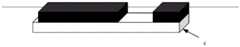
附图1是本实用新型一种海底电缆温度应力岸上模拟实验装置示意图。Accompanying drawing 1 is a schematic diagram of an onshore simulation experiment device of submarine cable temperature stress of the present invention.
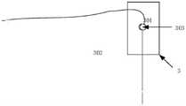
附图2是短距离空间分布率测试示意图。Figure 2 is a schematic diagram of a short-distance spatial distribution rate test.
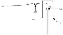
附图3是长距离空间分布率测试示意图。Figure 3 is a schematic diagram of a long-distance spatial distribution rate test.
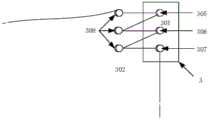
附图4是恒温烘箱内光纤放置示意图。Figure 4 is a schematic diagram of the placement of optical fibers in a constant temperature oven.
附图5是固定在高精度位移平台结构示意图。Figure 5 is a schematic diagram of the structure fixed on a high-precision displacement platform.
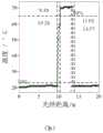
附图6是短距离空间分布率测试曲线图;其中图6(a)是测试光纤为1m光纤的空间分辨率测试曲线图,图6(b)是测试光纤为2m的空间分辨率测试曲线图。Accompanying drawing 6 is the short-distance spatial distribution rate test graph; Wherein Fig. 6 (a) is that the test fiber is the spatial resolution test graph of 1m optical fiber, and Fig. 6 (b) is that the test fiber is the spatial resolution test graph of 2m .
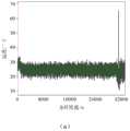
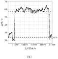
附图7是长距离空间分布率测试曲线图;其中图7(a)是31km光纤的空间分辨率测试曲线图,图7(b)是测试光纤100m的局部曲线图。Fig. 7 is a long-distance spatial distribution rate test graph; Fig. 7(a) is a spatial resolution test graph of a 31km fiber, and Fig. 7(b) is a partial graph of a 100m test fiber.
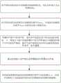
附图8是海底电缆岸上模拟实验检测框图。Figure 8 is a block diagram of the detection of the submarine cable onshore simulation experiment.
附图标记说明:Description of reference numbers:
1为光纤盘,2为光纤温度应变分析仪,3为恒温烘箱,4为高精度位移平台;301为室温,302为大于室温20℃,303短距离光纤长度,304长距离光纤长度,305为当前空间分布率光纤长度,306为小于空间分布率光纤长度,307为大于2倍当前空间分布率光纤长度,308远大于当前空间分布率光纤长度。1 is an optical fiber disk, 2 is an optical fiber temperature strain analyzer, 3 is a constant temperature oven, and 4 is a high-precision displacement platform; 301 is room temperature, 302 is 20°C higher than room temperature, 303 is short-distance fiber length, 304 is long-distance fiber length, and 305 is The current spatial distribution rate fiber length, 306 is the fiber length less than the spatial distribution rate, 307 is the fiber length greater than 2 times the current spatial distribution rate, and 308 is much larger than the current spatial distribution rate fiber length.
具体实施方式Detailed ways
下面结合附图和实施例对本实用新型进行详细说明。The present utility model will be described in detail below with reference to the accompanying drawings and embodiments.
如图1所示,本实用新型提供的一种海底电缆温度应力岸上模拟实验装置,包括光纤盘1,光纤温度应变分析仪2,恒温烘箱3,以及高精度位移平台4。As shown in FIG. 1 , a submarine cable temperature stress onshore simulation experiment device provided by the present invention includes an optical fiber disk 1 , an optical fiber
测量时,待测光纤盘1中的光纤的一端与光纤温度应变分析仪2发射端相连,另一端依次与放入恒温烘箱3中的光纤和固定在高精度位移平台4上的光纤相连,最后与光纤温度应变分析仪2接收端相连,形成另一条光通路;通过改变接入光纤盘1长度来模拟实际海缆运行距离;利用放入恒温烘箱3中的光纤和浴槽外的光纤进行光纤温度应变分析仪2的空间分布率测试以及温度故障模拟;利用高精度位移平台4改变光纤应变大小来模拟应变故障;光纤温度应变分析仪2用于采集不同时刻的不同位置的布里渊位移频移。During measurement, one end of the optical fiber in the optical fiber disc 1 to be measured is connected to the transmitting end of the optical fiber
如图4所示,本实用新型提供的一种海底电缆温度应力岸上模拟实验装置,实验时,包括以下步骤:As shown in Figure 4, the utility model provides a kind of submarine cable temperature stress onshore simulation experiment device. During the experiment, the following steps are included:
1)如图2所示,首先进行短距离的空间分布率实验,将1m和2m裸光纤分别放入恒温烘箱3内,保证光纤处于自由松散状态,利用光纤温度应变分析仪2测量;1) As shown in Figure 2, first perform a short-distance spatial distribution rate experiment, put 1m and 2m bare optical fibers into a
2)如图3所示,进行长距离的空间分布率实验,在光纤温度应变分析仪2发射端连入31km光纤盘然后,将100m裸光纤分别放入恒温烘箱3内,保证光纤处于自由松散状态,利用光纤温度应变分析仪2测量;2) As shown in Figure 3, carry out a long-distance spatial distribution rate experiment, connect a 31km optical fiber disk to the transmitting end of the optical fiber
3)如图4所示,将不同长度的光纤依次放置在恒温烘箱3内,保证光纤处于自由松散状态;其中301为大于室温20℃,302为室温,303为当前空间分布率光纤长度,304为小于空间分布率光纤长度,305为大于2倍当前空间分布率光纤长度,306远大于当前空间分布率光纤长度;3) As shown in Figure 4, the optical fibers of different lengths are placed in the
4)如图3所示,将不同长度的光纤固定在高精度位移平台4上,并保证在高精度位移平台4上光纤状态处于绷紧状态;4) As shown in Figure 3, fix the optical fibers of different lengths on the high-
5)待测光纤盘1中的光纤的一端与光纤温度应变分析仪2发射端相连,另一端依次与放入恒温烘箱3中的光纤和固定在高精度位移平台4上的光纤相连,最后与光纤温度应变分析仪2接收端相连,形成另一条光通路;5) One end of the optical fiber in the optical fiber disc 1 to be tested is connected with the transmitting end of the optical fiber
6)改变恒温烘箱3的温度以及高精度位移平台4的位移大小,记录不同条件下光纤温度应变分析仪2测量的布里渊位移频移。6) Change the temperature of the
具体来说,步骤1)1m和2m短距离的空间分布率测试实验,对其结果处理得到温度和光纤长度的曲线图如图6所示。Specifically, step 1) a short-distance spatial distribution rate test experiment of 1 m and 2 m, and a graph of temperature and fiber length obtained by processing the results is shown in Figure 6.
步骤2)31km长距离距离的空间分布率测试实验,对其结果处理得到温度和光纤长度的曲线图如图7所示。Step 2) The spatial distribution rate test experiment for a long distance of 31 km, and the graph of temperature and fiber length obtained by processing the results is shown in Figure 7.
步骤3)将等于当前空间分布率光纤长度、远大于当前空间分布率光纤长度、小于空间分布率光纤长度、远大于当前空间分布率光纤长度、大于2倍当前空间分布率光纤长度依次放入恒温烘箱3,得到不同形状的曲线。Step 3) Put the fiber length equal to the current spatial distribution rate, the fiber length far greater than the current spatial distribution rate, the fiber length less than the spatial distribution rate, the fiber length far greater than the current spatial distribution rate, and the fiber length greater than 2 times the current spatial distribution rate into the constant temperature in turn.
步骤5)待测光纤盘1可以根据实际海缆运行情况的长度进行模拟,而且可以在光纤盘1的前后不同位置进行温度应变故障模拟。Step 5) The optical fiber reel 1 to be tested can be simulated according to the length of the actual submarine cable operation, and temperature strain fault simulation can be performed at different positions before and after the optical fiber reel 1 .
步骤6)将光纤1m、2m、3m长度分别固定在高精度位移平台4,通过移动高精度位移平台4移动0.1mm、0.2mm、0.3mm、0.4mm、0.5mm模拟100με、200μ、300με、400με、500με。通过改变恒温烘箱分别为大于室温20℃、30℃、40℃、50℃、60℃。Step 6) Fix the 1m, 2m, and 3m lengths of the optical fibers on the high-
步骤6)布里渊频移与同一时刻光纤的温度、应变的关系如式(1)所示:Step 6) The relationship between the Brillouin frequency shift and the temperature and strain of the fiber at the same time is shown in formula (1):
vB(T,ε)=vB(T0,ε0)+CυT(T-T0)+Cυε(ε-ε0)(1)vB (T,ε)=vB (T0 ,ε0 )+CυT (TT0 )+Cυε (ε-ε0 )(1)
其中vB(T0,ε0)、vB(T,ε)为光纤温度应变分析仪在待测光纤布里渊散射光频移量,ε0、ε为高精度位移平台上稳定后测量得到的光纤的应变值,T0、T为待测恒温烘箱温度稳定后测量得到的光纤的温度值,CvT、Cvε分别为布里渊频移温度系数、布里渊频移应变系数。where vB (T0 ,ε0 ), vB (T,ε) are the frequency shift of the fiber temperature strain analyzer on the fiber to be measured Brillouin scattering light, ε0 , ε are the measurement on the high-precision displacement platform after stabilization The obtained strain value of the optical fiber, T0 and T are the temperature values of the optical fiber measured after the temperature of the constant temperature oven to be measured is stabilized, and CvT and Cvε are the Brillouin frequency shift temperature coefficient and the Brillouin frequency shift strain coefficient, respectively.
Claims (4)
Priority Applications (1)
| Application Number | Priority Date | Filing Date | Title |
|---|---|---|---|
| CN201921010752.0UCN210108389U (en) | 2019-06-28 | 2019-06-28 | An onshore simulation experiment device for submarine cable temperature stress |
Applications Claiming Priority (1)
| Application Number | Priority Date | Filing Date | Title |
|---|---|---|---|
| CN201921010752.0UCN210108389U (en) | 2019-06-28 | 2019-06-28 | An onshore simulation experiment device for submarine cable temperature stress |
Publications (1)
| Publication Number | Publication Date |
|---|---|
| CN210108389Utrue CN210108389U (en) | 2020-02-21 |
Family
ID=69567814
Family Applications (1)
| Application Number | Title | Priority Date | Filing Date |
|---|---|---|---|
| CN201921010752.0UActiveCN210108389U (en) | 2019-06-28 | 2019-06-28 | An onshore simulation experiment device for submarine cable temperature stress |
Country Status (1)
| Country | Link |
|---|---|
| CN (1) | CN210108389U (en) |
Cited By (1)
| Publication number | Priority date | Publication date | Assignee | Title |
|---|---|---|---|---|
| CN110186489A (en)* | 2019-06-28 | 2019-08-30 | 中国南方电网有限责任公司超高压输电公司广州局 | A kind of submarine cable temperature stress imitative experimental appliance and method on the bank |
- 2019
- 2019-06-28CNCN201921010752.0Upatent/CN210108389U/enactiveActive
Cited By (2)
| Publication number | Priority date | Publication date | Assignee | Title |
|---|---|---|---|---|
| CN110186489A (en)* | 2019-06-28 | 2019-08-30 | 中国南方电网有限责任公司超高压输电公司广州局 | A kind of submarine cable temperature stress imitative experimental appliance and method on the bank |
| CN110186489B (en)* | 2019-06-28 | 2023-12-15 | 中国南方电网有限责任公司超高压输电公司广州局 | A shore simulation experimental device and method for temperature stress of submarine cables |
Similar Documents
| Publication | Publication Date | Title |
|---|---|---|
| CN102384725B (en) | Tunnel convergence deformation distribution fiber monitoring method and system thereof | |
| CN110186489B (en) | A shore simulation experimental device and method for temperature stress of submarine cables | |
| CN103033285A (en) | Simultaneous measurement method of temperature and strain of laid photoelectric composite cable | |
| WO2013071788A1 (en) | Temperature cycling test device for optical fiber composite phase conductor connector box and test method | |
| CN103048557A (en) | Testing device and testing method for allowable carrying capacity performance of OPPC (Optical Phase Conductor) | |
| CN104635079B (en) | One kind is based on whole distributed electric aerial optical cable load monitoring method | |
| CN103616101A (en) | Method for detecting optical fiber composite ground wire icing state of electric transmission line | |
| CN112887017B (en) | Positioning method and positioning system for optical cable connecting tower | |
| CN117335872A (en) | Distributed optical fiber sensing device and OPGW optical cable icing monitoring method | |
| CN210108389U (en) | An onshore simulation experiment device for submarine cable temperature stress | |
| CN110118644B (en) | A device and method for testing optical fiber microbend loss in OPLC cable | |
| CN104019835B (en) | Long-distance cable site machinery characteristic test system and method | |
| CN209764294U (en) | Long-distance cable continuous temperature monitoring system with automatic division of monitoring area | |
| CN210222163U (en) | An onshore simulation experiment device for submarine cable current carrying capacity | |
| CN106568461A (en) | Fiber-optic gyroscope multi-physics field acceleration test method and fiber-optic gyroscope multi-physics field acceleration test apparatus | |
| CN118623781A (en) | A method and device for decoupling temperature and strain of OPGW optical cable based on zero strain reference point and ANN algorithm | |
| CN104101379A (en) | Laid sensing optical fiber temperature and strain simultaneous measurement method based on BOTDR | |
| CN209745526U (en) | Device for testing microbending loss of optical fiber in OPLC (optical fiber composite liquid crystal) cable | |
| CN209727156U (en) | A kind of OPLC flattens the device of experiment fibre strain and synchro measure of decaying | |
| CN110187216A (en) | A kind of submarine cable current-carrying capacity imitative experimental appliance and method on the bank | |
| CN204964071U (en) | Portable optic fibre calibration device | |
| CN118033280A (en) | Current-carrying capacity monitoring method and device, storage medium and electronic device | |
| CN112305639B (en) | Optical fiber acquisition chain test system and method | |
| CN213397440U (en) | On-site calibration device of cable tunnel distributed optical fiber temperature measurement system | |
| Cheng et al. | Measurement Method for Temperature Sensitivity Coefficient of Embedded Optical Fiber in High-Voltage XLPE Cable—Shorter Than Spatial Resolution of BOTDR |
Legal Events
| Date | Code | Title | Description |
|---|---|---|---|
| GR01 | Patent grant | ||
| GR01 | Patent grant | ||
| TR01 | Transfer of patent right | ||
| TR01 | Transfer of patent right | Effective date of registration:20230810 Address after:570000 Unit B, 14 #, Fortune Plaza, 103 Binhai Avenue, Haikou City, Hainan Province Patentee after:Haikou Branch of Guangzhou Bureau of China Southern Power Grid Co.,Ltd. Patentee after:XI'AN JIAOTONG University Address before:510670 Guangzhou Bureau of Extra High Voltage Transmission Company of China Southern Power Grid Co., Ltd. in Guangzhou, Guangdong Province Patentee before:GUANGZHOU BUREAU OF EXTRA HIGH VOLTAGE TRANSMISSION COMPANY OF CHINA SOUTHERN POWER GRID Co.,Ltd. Patentee before:XI'AN JIAOTONG University |