CN210072405U - Unmanned aerial vehicle cooperative control verification platform - Google Patents
Unmanned aerial vehicle cooperative control verification platformDownload PDFInfo
- Publication number
- CN210072405U CN210072405UCN201920535980.3UCN201920535980UCN210072405UCN 210072405 UCN210072405 UCN 210072405UCN 201920535980 UCN201920535980 UCN 201920535980UCN 210072405 UCN210072405 UCN 210072405U
- Authority
- CN
- China
- Prior art keywords
- unmanned aerial
- uav
- aerial vehicle
- verification platform
- controller
- Prior art date
- Legal status (The legal status is an assumption and is not a legal conclusion. Google has not performed a legal analysis and makes no representation as to the accuracy of the status listed.)
- Active
Links
Images

Landscapes
- Traffic Control Systems (AREA)
- Navigation (AREA)
Abstract
Translated fromChinese
Description
Translated fromChinese技术领域technical field
本实用新型涉及无人机协同控制验证领域,特别是涉及一种无人机协同控制验证平台。The utility model relates to the field of unmanned aerial vehicle collaborative control verification, in particular to an unmanned aerial vehicle collaborative control verification platform.
背景技术Background technique
无人机又可以看作是空中机器人,一种能够完成一定程度的自主控制,能在空中进行可控飞行,从而可以通过携带特定设备完成相应任务的非载人飞行器。与载人飞行器相比,它体积小、成本低、安全性好,更适合执行重复性的或危险性高的任务,因此在民用和军用领域有广泛的应用前景。然而,当单架无人机执行任务时,它能完成的工作是受到制约的,对于更为复杂的任务,需要多架协同执行任务,可以通过合理分配携带的设备并形成合适的队形,同时覆盖较大区域,以更高效率协同完成任务,具体应用包括协同侦察、探测以及围捕等。在多机协同作业时,机群一般有必要形成合适的队形。一方面,无人机之间保持合适的间距有助于避免发生碰撞或者有的无人机脱离机群的情况;另一方面,在一些任务中无人机之间有必要形成指定的队形,例如通信中继等。因此,自主协同控制是无人机机群执行各种任务的重要基础。UAVs can also be regarded as aerial robots, a kind of unmanned aerial vehicle that can achieve a certain degree of autonomous control and controllable flight in the air, so that it can complete corresponding tasks by carrying specific equipment. Compared with manned aircraft, it has small size, low cost, good safety, and is more suitable for performing repetitive or high-risk tasks, so it has broad application prospects in the civil and military fields. However, when a single UAV performs a task, the work it can accomplish is limited. For more complex tasks, multiple aircraft are required to perform tasks collaboratively. By rationally distributing the equipment carried and forming a suitable formation, At the same time, it covers a large area and completes tasks collaboratively with higher efficiency. Specific applications include collaborative reconnaissance, detection, and round-up. In the multi-machine cooperative operation, it is generally necessary for the fleet to form a suitable formation. On the one hand, maintaining a proper distance between UAVs helps avoid collisions or when some UAVs leave the swarm; on the other hand, in some missions, it is necessary to form a designated formation between UAVs. For example, communication relay, etc. Therefore, autonomous cooperative control is an important basis for UAV swarms to perform various tasks.
目前大多数的无人设备协同理论的验证平台都是基于仿真的软件,用仿真软件模拟出无人设备的运行状态,然后根据仿真运行过程中生成的各种参数评价无人设备协同算法的优劣性,然而,仿真软件无法做到完全还原无人设备的运行状态,因此,仿真软件模拟出的无人设备协同算法的评估所需要的各种数据不够精确,如何搭建一个现实的环境来采集无人设备在运行过程中的各种参数,来评价无人设备协同算法的优劣性是亟待解决的重要问题。At present, most of the verification platforms for the unmanned equipment coordination theory are based on simulation software. The simulation software is used to simulate the operation state of the unmanned equipment, and then the optimal performance of the unmanned equipment cooperation algorithm is evaluated according to various parameters generated during the simulation operation. However, the simulation software cannot completely restore the running state of the unmanned equipment. Therefore, the various data required for the evaluation of the unmanned equipment collaborative algorithm simulated by the simulation software is not accurate enough. How to build a realistic environment to collect It is an important problem to be solved urgently to evaluate the pros and cons of the cooperative algorithm of unmanned equipment based on various parameters during the operation of unmanned equipment.
实用新型内容Utility model content
本实用新型的目的是提供一种无人机协同控制验证平台,能够现实的呈现无人机在协同控制算法下的运行状态,提高了对协同控制算法评估的准确度。The purpose of the utility model is to provide an unmanned aerial vehicle cooperative control verification platform, which can realistically present the operation state of the unmanned aerial vehicle under the cooperative control algorithm, and improve the accuracy of the evaluation of the cooperative control algorithm.
为实现上述目的,本实用新型提供了如下方案:For achieving the above object, the utility model provides the following scheme:
一种无人机协同控制验证平台,包括:An unmanned aerial vehicle cooperative control verification platform, comprising:
多个无人机,各所述无人机上均集成有第一控制器,第一控制器根据无人机协同控制算法控制所述无人机飞行;a plurality of unmanned aerial vehicles, each of the unmanned aerial vehicles is integrated with a first controller, and the first controller controls the flying of the unmanned aerial vehicles according to the unmanned aerial vehicle collaborative control algorithm;
定位系统,包括UWB导航定位系统和集成在所述无人机上的GPS芯片,所述UWB导航定位系统位于室内,所述GPS芯片与所述第一控制器电连接;a positioning system, including a UWB navigation and positioning system and a GPS chip integrated on the drone, the UWB navigation and positioning system is located indoors, and the GPS chip is electrically connected to the first controller;
地面站,包括用于向所述无人机发送指令的第二控制器和用于显示所述无人机位置的显示器;和a ground station including a second controller for sending instructions to the drone and a display for displaying the location of the drone; and
通信模块,所述地面站通过所述通信模块与各所述无人机进行信息交互,各所述无人机之间通过所述通信模块进行通信。A communication module, the ground station exchanges information with each of the UAVs through the communication module, and communicates between the UAVs through the communication module.
可选的,各所述无人机上还集成有用于检测重力和加速度的三轴加速度计、用于检测机体角速度的三片单轴陀螺仪和用于检测地磁场方向的三轴电子罗盘。Optionally, each of the UAVs is further integrated with a three-axis accelerometer for detecting gravity and acceleration, three single-axis gyroscopes for detecting the angular velocity of the body, and a three-axis electronic compass for detecting the direction of the geomagnetic field.
可选的,所述无人机上还集成有测量无人机高度的激光测距传感器。Optionally, the UAV is further integrated with a laser ranging sensor for measuring the height of the UAV.
可选的,所述通信模块为XBee通信模块。Optionally, the communication module is an XBee communication module.
可选的,所述无人机上还集成有软件接口,外部程序通过所述软件接口载入所述第一控制器。Optionally, the UAV is further integrated with a software interface, and an external program is loaded into the first controller through the software interface.
可选的,所述UWB导航定位系统包括PC主机、锚点和标签,所述锚点布设于设定位置,所述标签安装于所述无人机机架上,所述标签用于向所述锚点发送定位请求,所述锚点用于接收所述标签的请求信号并通过网口将所述信号传输至所述PC主机,所述PC主机用于解算得到所述无人机的位置信息。Optionally, the UWB navigation and positioning system includes a PC host, an anchor point and a tag, the anchor point is arranged at a set position, the tag is installed on the drone rack, and the tag is used to send information to all The anchor point sends a positioning request, and the anchor point is used to receive the request signal of the tag and transmit the signal to the PC host through the network port, and the PC host is used to obtain the location information.
可选的,所述无人机协同控制验证平台还包括用于控制所述无人机飞行的遥控器。Optionally, the UAV collaborative control verification platform further includes a remote controller for controlling the flight of the UAV.
可选的,所述无人机上还集成有数据存储器。Optionally, the UAV is further integrated with a data memory.
根据本实用新型提供的具体实施例,本实用新型公开了以下技术效果:本实用新型提供的无人机协同控制验证平台包括:多个无人机、定位系统、地面站和通信模块,各所述无人机上均集成有第一控制器,第一控制器根据无人机协同控制算法控制所述无人机飞行;定位系统包括UWB导航定位系统和集成在所述无人机上的GPS芯片,所述GPS芯片用于无人机在室外环境下的定位,所述UWB导航定位系统用于无人机在室内环境下的定位;地面站用于对无人机发送控制指令以及实时显示各无人机的位置。可见,本实用新型提供的供无人机协同控制算法验证的平台,能够使无人机的协同控制算法的优劣能够以实物的形式得到验证,与现有技术中采用仿真软件的形式进行验证相比较,具有评估准确度高的优势。According to the specific embodiment provided by the present utility model, the present utility model discloses the following technical effects: the unmanned aerial vehicle collaborative control verification platform provided by the present utility model includes: a plurality of unmanned aerial vehicles, a positioning system, a ground station and a communication module; A first controller is integrated on the UAV, and the first controller controls the UAV to fly according to the UAV collaborative control algorithm; the positioning system includes a UWB navigation and positioning system and a GPS chip integrated on the UAV, The GPS chip is used for the positioning of the drone in the outdoor environment, and the UWB navigation and positioning system is used for the positioning of the drone in the indoor environment; the ground station is used for sending control instructions to the drone and displaying each The position of the man-machine. It can be seen that the platform for the verification of the collaborative control algorithm of the UAV provided by the present utility model can make the advantages and disadvantages of the collaborative control algorithm of the UAV can be verified in the form of physical objects, and can be verified in the form of simulation software in the prior art. In comparison, it has the advantage of high evaluation accuracy.
附图说明Description of drawings
为了更清楚地说明本实用新型实施例或现有技术中的技术方案,下面将对实施例中所需要使用的附图作简单地介绍,显而易见地,下面描述中的附图仅仅是本实用新型的一些实施例,对于本领域普通技术人员来讲,在不付出创造性劳动的前提下,还可以根据这些附图获得其他的附图。In order to more clearly illustrate the embodiments of the present invention or the technical solutions in the prior art, the accompanying drawings required in the embodiments will be briefly introduced below. Obviously, the drawings in the following description are only of the present invention. For some embodiments of the present invention, for those of ordinary skill in the art, other drawings can also be obtained from these drawings without any creative effort.
图1为本实用新型实施例无人机协同控制验证平台的系统框图;1 is a system block diagram of an unmanned aerial vehicle collaborative control verification platform according to an embodiment of the present invention;
图2为本实用新型实施例UWB导航定位系统框图。FIG. 2 is a block diagram of a UWB navigation and positioning system according to an embodiment of the present invention.
具体实施方式Detailed ways
下面将结合本实用新型实施例中的附图,对本实用新型实施例中的技术方案进行清楚、完整地描述,显然,所描述的实施例仅仅是本实用新型一部分实施例,而不是全部的实施例。基于本实用新型中的实施例,本领域普通技术人员在没有做出创造性劳动前提下所获得的所有其他实施例,都属于本实用新型保护的范围。The technical solutions in the embodiments of the present utility model will be clearly and completely described below with reference to the accompanying drawings in the embodiments of the present utility model. Obviously, the described embodiments are only a part of the embodiments of the present utility model, rather than all the implementations. example. Based on the embodiments of the present invention, all other embodiments obtained by those of ordinary skill in the art without creative work fall within the protection scope of the present invention.
本实用新型的目的是提供一种无人机协同控制验证平台,能够现实的呈现无人机在协同控制算法下的运行状态,提高了对协同控制算法评估的准确度。The purpose of the utility model is to provide an unmanned aerial vehicle cooperative control verification platform, which can realistically present the operation state of the unmanned aerial vehicle under the cooperative control algorithm, and improve the accuracy of the evaluation of the cooperative control algorithm.
为使本实用新型的上述目的、特征和优点能够更加明显易懂,下面结合附图和具体实施方式对本实用新型作进一步详细的说明。In order to make the above objects, features and advantages of the present utility model more clearly understood, the present utility model will be described in further detail below with reference to the accompanying drawings and specific embodiments.
图1为本实用新型实施例无人机2协同控制验证平台的系统框图,如图1 所示,本实用新型提供的无人机2协同控制验证平台包括:多个无人机2、定位系统、地面站4和通信模块3,其中,各无人机2上均集成有第一控制器,第一控制器根据无人机协同控制算法控制所述无人机飞行;定位系统包括UWB导航定位系统1和集成在无人机2上的GPS芯片,UWB导航定位系统 1位于室内,GPS芯片与第一控制器电连接;地面站4包括用于向无人机2发送指令的第二控制器和用于显示无人机2位置的显示器;地面站4通过通信模块3与各无人机2进行信息交互,各无人机2之间通过通信模块3进行通信。1 is a system block diagram of an unmanned
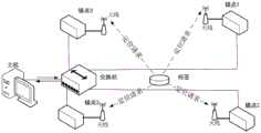
在上述实施例的基础上,作为本实用新型的一个实施例,UWB导航定位系统1包括PC主机、锚点和标签,锚点布设于设定位置,标签安装于无人机 2机架上,标签用于向锚点发送定位请求,锚点用于接收信号并通过网口将信号传输至PC主机,PC主机用于解算得到无人机2的位置信息。On the basis of the above embodiment, as an embodiment of the present utility model, the UWB navigation and
在上述实施例的基础上,作为本实用新型的一个实施例,各无人机2上还集成有用于检测重力和加速度的三轴加速度计、用于检测机体角速度的三片单轴陀螺仪和用于检测地磁场方向的三轴电子罗盘。On the basis of the above-mentioned embodiment, as an embodiment of the present utility model, each
在上述实施例的基础上,作为本实用新型的一个实施例,无人机2上还集成有测量无人机高度的激光测距传感器。On the basis of the above-mentioned embodiment, as an embodiment of the present invention, the
通信模块为XBee通信模块,用于提供通信网络,通信模块也可以包括 XBee通信模块、WiFi通信模块和3G/4G/5G通信模块等通信模块中的多种通信模块的配合使用。无人机上还集成有软件接口,外部程序通过软件接口载入第一控制器。The communication module is an XBee communication module, which is used to provide a communication network. The communication module may also include a combination of various communication modules in the communication modules such as the XBee communication module, the WiFi communication module, and the 3G/4G/5G communication module. A software interface is also integrated on the drone, and an external program is loaded into the first controller through the software interface.
无人机可以为四旋翼无人机,四旋翼无人机是运动主体,定位系统为四旋翼无人机提供导航数据,地面站监控整个机群状态,整个系统由通信模块采用无线的方式联系起来。其中,每一架无人机都具备室外和室内条件下基于定位系统的自主飞行能力,同时各配备相应的遥控器用于紧急情况处理,无人机与无人机间、无人机与地面站间均可以通过通信模块进行无线通信,一方面用于编队飞行时无人机之间的协调,另一方面用于地面站与机群的交互。通过地面站软件,可以对机群系统的状态进行监控,并发送参数配置指令或编队飞行、航迹飞行指令,无人机接收到指令后,根据自身控制器中的协同控制算法计算飞行轨迹以及协调与其他无人机之间位置关系。本平台中的四旋翼无人机利用自身携带的传感器和外部定位系统精确确定绝对位置和相对位置,利用XBee 通信模块和地面站进行信息共享,具备编队协同飞行的能力,并提供协同控制层面的软件接口,可对自主开发的协同控制算法进行验证。The UAV can be a quad-rotor UAV, the quad-rotor UAV is the main body of motion, the positioning system provides navigation data for the quad-rotor UAV, the ground station monitors the status of the entire fleet, and the entire system is wirelessly connected by the communication module . Among them, each UAV has the ability to fly autonomously based on the positioning system under outdoor and indoor conditions, and each is equipped with a corresponding remote controller for emergency handling, between UAVs and UAVs, between UAVs and ground stations Both can communicate wirelessly through the communication module, on the one hand, it is used for the coordination between UAVs during formation flight, and on the other hand, it is used for the interaction between the ground station and the fleet. Through the ground station software, the status of the fleet system can be monitored, and parameter configuration instructions or formation flight and track flight instructions can be sent. After the UAV receives the instructions, it calculates the flight trajectory and coordinates according to the cooperative control algorithm in its own controller. Positional relationship with other drones. The quadrotor UAV in this platform uses its own sensors and external positioning system to accurately determine the absolute position and relative position, uses the XBee communication module and the ground station to share information, has the ability to fly in formation, and provides coordinated control level. The software interface can verify the self-developed collaborative control algorithm.
地面站是指地面系统监控操作端,是一套软件运行在Windows平台上,基于Labview16.0编写,通过XBee无线通信模块与无人机进行信息交互,功能主要包括两部分:接收并显示各架无人机的状态,向机群或特定无人机发送参数或指令。系统中,每一架无人机发给地面站的信息包括姿态、位置等自身状态信息,每架无人机的详细信息显示在界面右半边的相应位置,而所有无人机的水平方向位置则统一显示在界面左半边的XY图上,以方便监控机群编队效果。界面上不同无人机的信息用不同颜色进行标记区分。The ground station refers to the monitoring operation end of the ground system. It is a set of software that runs on the Windows platform and is written based on Labview16.0. It exchanges information with the UAV through the XBee wireless communication module. The function mainly includes two parts: receiving and displaying each frame. The status of the drone, sending parameters or commands to the swarm or to a specific drone. In the system, the information sent by each UAV to the ground station includes its own status information such as attitude and position. The detailed information of each UAV is displayed in the corresponding position on the right half of the interface, and the horizontal position of all UAVs is displayed. It will be uniformly displayed on the XY chart on the left half of the interface to facilitate monitoring the effect of the fleet formation. The information of different drones on the interface is marked with different colors to distinguish.
可以通过地面站向机群发送的参数和指令包括:飞行控制和编队控制的控制参数、航迹指令、编队队形指令、通信拓扑配置等。发送参数和指令可以直接在监控画面上点击弹出发送窗口进行发送。本实用新型中,地面站不执行任务规划、航迹生成、飞行控制等任务,因此,不需要实时向机群发送控制指令,理论上机群与地面站断开通信后不会对机群的控制造成影响。The parameters and instructions that can be sent to the fleet through the ground station include: flight control and formation control control parameters, track instructions, formation instructions, communication topology configuration, etc. Sending parameters and instructions can be sent directly by clicking the pop-up sending window on the monitoring screen. In the present utility model, the ground station does not perform tasks such as mission planning, track generation, flight control, etc. Therefore, it is not necessary to send control commands to the fleet in real time. In theory, the disconnection of communication between the fleet and the ground station will not affect the control of the fleet. .
定位系统指的是GPS以及UWB导航定位系统,本平台对以上两种定位方式都支持,根据场地不同均可随时调整,GPS定位系统适用于户外大型空旷场地,UWB定位系统适用于室内以及户外小型场地。其中GPS定位系统由 GPS芯片构成,位于四旋翼无人机上,通过串口线与第一控制器相连接,第一控制器接收GPS信号解算出当前经纬度,再转化为参考惯性系下的全局坐标。 UWB定位系统由PC主机、锚点、标签、交换机、电源、网线构成,软件为主机解算软件安装于PC主机上,如图2所示。锚点布设于已知位置,标签安装于四旋翼机架上,在锚点覆盖的区域内,标签发送定位请求,锚点接收信号并通过网口送PC主机,经过PC主机解算可以为四旋翼提供位置信息。The positioning system refers to GPS and UWB navigation and positioning systems. This platform supports both of the above two positioning methods, and can be adjusted at any time according to different sites. The GPS positioning system is suitable for large outdoor open spaces, and the UWB positioning system is suitable for indoor and outdoor small. site. The GPS positioning system consists of a GPS chip, which is located on the four-rotor UAV, and is connected to the first controller through a serial line. The UWB positioning system consists of a PC host, anchor points, labels, switches, power supplies, and network cables. The software is the host computer's solution software installed on the PC host, as shown in Figure 2. The anchor point is arranged at a known position, and the tag is installed on the quadrotor frame. In the area covered by the anchor point, the tag sends a positioning request, and the anchor point receives the signal and sends it to the PC host through the network port. The rotor provides position information.
四旋翼无人机是指搭载自主研发飞控系统的四轴多旋翼无人机,具备在室内外环境下检测自身位置姿态并对其进行控制的自主飞行能力以及与邻居四旋翼和地面站通信的能力。同时每架无人机配备遥控器,可使操作员在有需要时能随时人工干预四旋翼无人机飞行,从而提高安全性。Quad-rotor UAV refers to a four-axis multi-rotor UAV equipped with a self-developed flight control system. It has the ability to detect its own position and attitude in indoor and outdoor environments and control it autonomously, as well as communicate with neighboring quad-rotors and ground stations. Ability. At the same time, each UAV is equipped with a remote control, which enables the operator to manually intervene in the flight of the quadrotor UAV at any time when necessary, thereby improving safety.
本平台中的AHRS(AttitudeHeadingReferenceSystem,航姿参考系统) 使用分立传感器元件搭建,包括用于检测重力和加速度的一片三轴加速度计、用于检测机体角速度的三片单轴陀螺仪和用于检测地磁场方向的一个三轴电子罗盘,都位于各无人机的控制板上,来实现对无人机姿态的解算。机身水平方向上的位置使用GPS/UWB定位系统测量,高度使用激光测距模块测量。利用测得的位置和加速度信息,通过自行编写的位置滤波算法,可以得到精度和带宽更高的无人机位置和速度信息。本平台中,每架无人机携带一片2G内存的MicroSD卡,用于数据记录。本系统中使用XBee模块用于无人机和无人机、无人机和地面站之间的无线通信。XBee模块具有自组网的能力,支持点对点通信和广播,满足多机编队飞行这类应用的需求。每架无人机上使用的处理器为一片TMS320F28335DSP(DigitalSignalProcessor,数字信号处理器),包含丰富的接口及运算资源,可以满足系统需求。飞控系统全部相关软件均在 DSP上运行,包括数据采集、滤波、飞行控制、编队控制、通信、数据记录等。四旋翼的姿态滤波与控制等底层任务运行频率为500Hz,由高优先级的时钟中断保证其实时性。The AHRS (AttitudeHeadingReferenceSystem) in this platform is built with discrete sensor components, including a three-axis accelerometer for detecting gravity and acceleration, three single-axis gyroscopes for detecting the angular velocity of the body, and a ground for detecting ground A three-axis electronic compass in the direction of the magnetic field is located on the control board of each UAV to realize the calculation of the UAV attitude. The position in the horizontal direction of the fuselage is measured by GPS/UWB positioning system, and the height is measured by laser ranging module. Using the measured position and acceleration information, the position and velocity information of the UAV with higher accuracy and bandwidth can be obtained through the self-written position filtering algorithm. In this platform, each drone carries a MicroSD card with 2G memory for data recording. The XBee module is used in this system for wireless communication between UAV and UAV, UAV and ground station. The XBee module has the ability of ad hoc networking, supports point-to-point communication and broadcast, and meets the needs of applications such as multi-machine formation flying. The processor used on each drone is a TMS320F28335DSP (Digital Signal Processor), which contains rich interfaces and computing resources to meet system requirements. All relevant software of the flight control system runs on the DSP, including data acquisition, filtering, flight control, formation control, communication, data recording, etc. The low-level tasks such as attitude filtering and control of the quadrotor run at a frequency of 500Hz, and the real-time performance is guaranteed by the high-priority clock interrupt.
本实用新型提供的无人机协同控制验证平台包括:多个无人机、定位系统、地面站和通信模块,各所述无人机上均集成有第一控制器;定位系统包括UWB 导航定位系统和集成在所述无人机上的GPS芯片,所述GPS芯片用于无人机在室外环境下的定位,所述UWB导航定位系统用于无人机在室内环境下的定位;地面站用于对无人机发送控制指令以及实时显示各无人机的位置。可见,本实用新型提供的供无人机协同控制算法验证的平台,能够使无人机的协同控制算法的优劣能够以实物的形式得到验证,与现有技术中采用仿真软件的形式进行验证相比较,具有评估准确度高的优势。The unmanned aerial vehicle collaborative control verification platform provided by the utility model includes: a plurality of unmanned aerial vehicles, a positioning system, a ground station and a communication module, each of the unmanned aerial vehicles is integrated with a first controller; the positioning system includes a UWB navigation and positioning system. and a GPS chip integrated on the drone, the GPS chip is used for the positioning of the drone in the outdoor environment, and the UWB navigation and positioning system is used for the positioning of the drone in the indoor environment; the ground station is used for Send control commands to drones and display the position of each drone in real time. It can be seen that the platform for the verification of the collaborative control algorithm of the UAV provided by the present utility model can make the advantages and disadvantages of the collaborative control algorithm of the UAV can be verified in the form of physical objects, and can be verified in the form of simulation software in the prior art. In comparison, it has the advantage of high evaluation accuracy.
本说明书中各个实施例采用递进的方式描述,每个实施例重点说明的都是与其他实施例的不同之处,各个实施例之间相同相似部分互相参见即可。The various embodiments in this specification are described in a progressive manner, and each embodiment focuses on the differences from other embodiments, and the same and similar parts between the various embodiments can be referred to each other.
本文中应用了具体个例对本实用新型的原理及实施方式进行了阐述,以上实施例的说明只是用于帮助理解本实用新型的方法及其核心思想;同时,对于本领域的一般技术人员,依据本实用新型的思想,在具体实施方式及应用范围上均会有改变之处。综上所述,本说明书内容不应理解为对本实用新型的限制。The principles and implementations of the present utility model are described herein using specific examples. The descriptions of the above embodiments are only used to help understand the method and the core idea of the present utility model; meanwhile, for those skilled in the art, according to The idea of the present utility model will have changes in the specific implementation and application scope. In conclusion, the content of this specification should not be construed as a limitation on the present invention.
Claims (8)
Translated fromChinesePriority Applications (1)
| Application Number | Priority Date | Filing Date | Title |
|---|---|---|---|
| CN201920535980.3UCN210072405U (en) | 2019-04-19 | 2019-04-19 | Unmanned aerial vehicle cooperative control verification platform |
Applications Claiming Priority (1)
| Application Number | Priority Date | Filing Date | Title |
|---|---|---|---|
| CN201920535980.3UCN210072405U (en) | 2019-04-19 | 2019-04-19 | Unmanned aerial vehicle cooperative control verification platform |
Publications (1)
| Publication Number | Publication Date |
|---|---|
| CN210072405Utrue CN210072405U (en) | 2020-02-14 |
Family
ID=69437894
Family Applications (1)
| Application Number | Title | Priority Date | Filing Date |
|---|---|---|---|
| CN201920535980.3UActiveCN210072405U (en) | 2019-04-19 | 2019-04-19 | Unmanned aerial vehicle cooperative control verification platform |
Country Status (1)
| Country | Link |
|---|---|
| CN (1) | CN210072405U (en) |
Cited By (1)
| Publication number | Priority date | Publication date | Assignee | Title |
|---|---|---|---|---|
| CN110187695A (en)* | 2019-04-19 | 2019-08-30 | 北京航空航天大学 | A UAV collaborative control verification platform |
- 2019
- 2019-04-19CNCN201920535980.3Upatent/CN210072405U/enactiveActive
Cited By (1)
| Publication number | Priority date | Publication date | Assignee | Title |
|---|---|---|---|---|
| CN110187695A (en)* | 2019-04-19 | 2019-08-30 | 北京航空航天大学 | A UAV collaborative control verification platform |
Similar Documents
| Publication | Publication Date | Title |
|---|---|---|
| US11442473B2 (en) | Systems and methods for surveillance with a visual marker | |
| CN114063474B (en) | A Simulation Method of Semi-Physical Simulation System Based on UAV Swarm | |
| CN114488848B (en) | Unmanned aerial vehicle autonomous flight system and simulation experiment platform for indoor building space | |
| CN104808675B (en) | Somatosensory flight control system and terminal equipment based on intelligent terminal | |
| CN103472847B (en) | Unmanned plane power circuit polling flight path method for supervising and system | |
| CN110187695A (en) | A UAV collaborative control verification platform | |
| CN207133659U (en) | A kind of unmanned vehicle tele-control system | |
| CN107179777A (en) | Multiple agent cluster Synergistic method and multiple no-manned plane cluster cooperative system | |
| CN105302150A (en) | Unmanned aircraft infinite endurance system | |
| CN104808676B (en) | The full independent flight control system of quadrotor unmanned vehicle based on external view | |
| CN102854887A (en) | A UAV trajectory planning and remote synchronization control method | |
| CN106406345A (en) | Indoor multi-unmanned aerial vehicle formation control system based on Qt | |
| CN102424112A (en) | Three-layer airborne flight control device for micro four-rotor aerial vehicle | |
| CN110187700B (en) | Remote control system and method of bionic flapping-wing flying robot based on virtual reality | |
| US20240176367A1 (en) | Uav dispatching method, server, dock apparatus, system, and storage medium | |
| CN106781665A (en) | Unmanned plane parking position guidance system based on Internet of Things | |
| CN109799841A (en) | A kind of unmanned aerial vehicle ground control system, equipment and storage medium | |
| CN115758687A (en) | Unmanned aerial vehicle autopilot simulation platform | |
| CN108181924B (en) | Method and system for controlling unmanned aerial vehicle to fly on image interface | |
| CN113063401A (en) | Unmanned aerial vehicle aerial survey system | |
| CN113168190A (en) | Operation method, control equipment, operation drone, system and storage medium | |
| CN115981355A (en) | Unmanned aerial vehicle automatic cruise method and system capable of landing quickly and accurately | |
| CN210072405U (en) | Unmanned aerial vehicle cooperative control verification platform | |
| CN111736487B (en) | A hardware-in-the-loop simulation system and method for a rotary-wing unmanned aerial vehicle cooperative control system | |
| CN108417041A (en) | A rural road monitoring system and method based on quadrotor and cloud server |
Legal Events
| Date | Code | Title | Description |
|---|---|---|---|
| GR01 | Patent grant | ||
| GR01 | Patent grant |