CN209996391U - Staple cartridge assembly and medical stapler including the same - Google Patents
Staple cartridge assembly and medical stapler including the sameDownload PDFInfo
- Publication number
- CN209996391U CN209996391UCN201920474022.XUCN201920474022UCN209996391UCN 209996391 UCN209996391 UCN 209996391UCN 201920474022 UCN201920474022 UCN 201920474022UCN 209996391 UCN209996391 UCN 209996391U
- Authority
- CN
- China
- Prior art keywords
- staple
- staple cartridge
- cartridge assembly
- staples
- nail
- Prior art date
- Legal status (The legal status is an assumption and is not a legal conclusion. Google has not performed a legal analysis and makes no representation as to the accuracy of the status listed.)
- Withdrawn - After Issue
Links
Images


Landscapes
- Surgical Instruments (AREA)
Abstract
Description
Translated fromChinese技术领域technical field
本实用新型涉及医疗器械技术领域,具体涉及一种钉仓组件及包括其的医用吻合器。The utility model relates to the technical field of medical instruments, in particular to a staple cartridge assembly and a medical stapler including the same.
背景技术Background technique
消化道疾病是人类高发的疾病之一,在治疗过程中,常使用医用吻合器代替医生的手工操作对消化道等生理组织进行吻合。医用吻合器是一种常见的外科手术器械,大多采用轴向内装订方式,在手术时对食管、胃、肠道等生理组织形成端对端的、或者端对侧的吻合,吻合时两段组织内敛收容于医用吻合器内,击发完成后在组织上形成圆形吻合口,重建了人体通道。Digestive tract disease is one of the most common diseases in human beings. In the course of treatment, medical staplers are often used to perform anastomosis on physiological tissues such as the digestive tract instead of the manual operation of doctors. Medical stapler is a common surgical instrument, most of which use axial inward binding. During surgery, end-to-end or end-to-side anastomosis is formed on physiological tissues such as esophagus, stomach, and intestinal tract. It is restrained and accommodated in the medical stapler, and after the firing is completed, a circular anastomosis is formed on the tissue, and the human body passage is reconstructed.
现有技术中,医用吻合器包括医用吻合器本体、活动连接所述医用吻合器本体的操作把手以及与所述本体配合的钉砧组件。所述医用吻合器本体包括设于远端侧的钉仓组件和钉仓组件架。在本实用新型中,远端侧和近端侧是相对于操作者来说的,距离操作者较近的一端为近端侧,距离操作者较远的一端,即更靠近手术位置的一端为远端侧。在手术时,将钉仓组件和钉砧组件闭合,握持操作把手,可以推动吻合钉向组织运动,通过钉仓组件中的吻合钉在钉砧组件处的成型,将组织吻合。In the prior art, a medical stapler includes a medical stapler body, an operating handle movably connected to the medical stapler body, and an anvil assembly matched with the body. The medical stapler body includes a staple cartridge assembly and a staple cartridge assembly frame disposed on the distal side. In the present invention, the distal side and the proximal side are relative to the operator, the end that is closer to the operator is the proximal side, and the end that is farther away from the operator, that is, the end that is closer to the operating position is distal side. During the operation, the staple cartridge assembly and the staple anvil assembly are closed, and the operating handle is held to push the staples to move toward the tissue, and the tissue is anastomosed by forming the staples in the staple cartridge assembly at the staple anvil assembly.
现有的钉仓组件中,吻合钉多是一个个分离设置的,然而这样的吻合钉需要每个单独安装在钉仓组件的钉孔中,安装十分不便。In the existing staple cartridge assembly, the staples are mostly arranged separately one by one, however, such staples need to be installed in the staple holes of the staple cartridge assembly individually, which is very inconvenient to install.
实用新型内容Utility model content
针对现有技术中的问题,本实用新型的目的在于提供一种钉仓组件及包括其的医用吻合器,将吻合钉形成于一钉带上,安装和更换更加方便,设置凸块,方便吻合钉与钉带本体的脱离。In view of the problems in the prior art, the purpose of the present utility model is to provide a staple cartridge assembly and a medical stapler including the staple cartridge, the staples are formed on a staple belt, the installation and replacement are more convenient, and the protruding block is provided to facilitate anastomosis The disengagement of the nail from the body of the nail strip.
本实用新型实施例提供一种钉仓组件,用于医用吻合器,所述钉仓组件包括至少一个钉带和多个凸块,所述钉带包括沿所述医用吻合器的轴向方向延伸的钉带本体,所述钉带本体上设置有至少一排沿所述钉带本体的延伸方向依次排布的吻合钉,所述吻合钉通过其连接端连接至所述钉带本体;An embodiment of the present invention provides a staple cartridge assembly for a medical stapler, the staple cartridge assembly includes at least one staple tape and a plurality of protrusions, the staple tape includes a staple tape extending along the axial direction of the medical stapler The staple band body, the staple band body is provided with at least one row of staples arranged in sequence along the extension direction of the staple band body, and the staples are connected to the staple band body through their connecting ends;
所述凸块与所述吻合钉一一对应,所述凸块位于所对应的吻合钉的连接端的远端侧,且击发所述医用吻合器时,所述吻合钉的连接端与所述凸块相接触而断开与所述钉带本体的连接。The protruding blocks are in one-to-one correspondence with the staples, the protruding blocks are located on the distal side of the connecting ends of the corresponding staples, and when the medical stapler is fired, the connecting ends of the staples and the protruding The blocks come into contact to break the connection with the staple strip body.
可选地,所述钉带本体设置有两排所述吻合钉,且两排所述吻合钉沿所述钉带本体的延伸方向交错设置;两排所述吻合钉所对应的所述凸块沿所述钉带本体的延伸方向交错设置。Optionally, the staple band body is provided with two rows of the staples, and the two rows of the staples are arranged staggered along the extending direction of the staple band body; the protrusions corresponding to the two rows of the staples They are arranged staggered along the extending direction of the staple strip body.
可选地,两排所述吻合钉之间设置有一连杆,所述连杆的顶部设置有所述凸块。Optionally, a connecting rod is provided between the two rows of the staples, and the top of the connecting rod is provided with the protruding block.
可选地,所述钉带本体与各个所述凸块对应的位置分别开设有用于容纳所述凸块的凸块容纳口。Optionally, a position corresponding to each of the protruding blocks is respectively opened on the staple strip body with a protruding block accommodating opening for accommodating the protruding blocks.
可选地,所述凸块的远端侧面为从其远端侧向其近端侧逐渐上升的斜面。Optionally, the distal side of the protrusion is a slope gradually rising from the distal side to the proximal side thereof.
可选地,所述凸块的远端侧面的顶端平滑过渡至所述凸块的顶面。Optionally, the top end of the distal side surface of the protrusion smoothly transitions to the top surface of the protrusion.
可选地,所述凸块的近端侧面为从其远端侧向其近端侧逐渐上升的斜面。Optionally, the proximal side of the protrusion is a slope gradually rising from the distal side to the proximal side thereof.
可选地,所述凸块的近端侧面形成为刃口。Optionally, the proximal side of the projection is formed as a cutting edge.
可选地,所述钉带本体朝向所述医用吻合器的钉砧的一侧表面为钉仓组件面,所述凸块的顶端突出于所述钉仓组件面。Optionally, a side surface of the staple band body facing the staple anvil of the medical stapler is a staple cartridge assembly surface, and the top end of the protrusion protrudes from the staple cartridge assembly surface.
可选地,所述凸块的近端侧开设有一配合口,所述吻合钉的连接端具有一连接梁,且所述连接梁位于所述配合口中。Optionally, a mating port is defined on the proximal end side of the protruding block, a connecting beam is provided at the connecting end of the staple, and the connecting beam is located in the mating port.
可选地,所述钉仓组件还包括固定件,所述钉带的远端侧固定于所述固定件上。Optionally, the staple cartridge assembly further includes a fixing member, and the distal side of the staple tape is fixed on the fixing member.
可选地,每排所述钉带的两侧还分别设置有限位件,所述限位件沿所述医用吻合器的轴向方向延伸,且所述限位件限定所述吻合钉的出钉方向。Optionally, limiters are respectively provided on both sides of each row of the staple strips, the limiters extend along the axial direction of the medical stapler, and the limiters limit the exit of the staples. Nail direction.
可选地,所述钉仓组件还包括钉仓盖,所述钉仓盖覆盖于所述钉带本体的上表面,所述钉仓盖上开设有与所述吻合钉一一对应的出钉口。Optionally, the staple cartridge assembly further includes a staple cartridge cover, the staple cartridge cover covers the upper surface of the staple belt body, and the staple cartridge cover is provided with a one-to-one correspondence with the staples. mouth.
可选地,所述钉仓盖的出钉口处设置有所述凸块,所述凸块突出于所述钉仓盖的下表面。Optionally, the protruding block is provided at the nail outlet of the staple cartridge cover, and the protruding block protrudes from the lower surface of the staple cartridge cover.
可选地,初始状态下,所述吻合钉的连接端的远端侧面与所述凸块的近端侧面之间具有一定间隔。Optionally, in an initial state, there is a certain interval between the distal side surface of the connecting end of the staple and the proximal side surface of the projection.
本实用新型实施例还提供一种医用吻合器,包括任一项所述的钉仓组件。The embodiment of the present invention also provides a medical stapler, including any one of the staple cartridge assemblies.
本实用新型所提供的钉仓组件及包括其的医用吻合器具有如下优点:The staple cartridge assembly provided by the present utility model and the medical stapler comprising the same have the following advantages:
本实用新型提供了一种用于医用吻合器的钉仓组件,将吻合钉形成于一钉带上,安装和更换更加方便,在一次手术完成后,可以只更换钉带;在钉带本体上设置凸块,方便吻合钉与钉带本体的脱离,保证手术过程中吻合钉可以脱离钉仓组件而将组织吻合,从而避免手术中出现卡钉的情况,提高手术效果。The utility model provides a staple cartridge assembly for a medical stapler. The staples are formed on a staple belt, which is more convenient for installation and replacement. After one operation is completed, only the staple belt can be replaced; The protruding block is arranged to facilitate the detachment of the staples from the staple belt body, to ensure that the staples can be separated from the staple cartridge assembly and anastomosed to the tissue during the operation, thereby avoiding staple jamming during the operation and improving the surgical effect.
附图说明Description of drawings
通过阅读参照以下附图对非限制性实施例所作的详细描述,本实用新型的其它特征、目的和优点将会变得更明显。Other features, objects and advantages of the present invention will become more apparent upon reading the detailed description of non-limiting embodiments with reference to the following drawings.
图1是本实用新型一实施例的钉仓组件与钉砧和钉仓组件架配合的示意图;FIG. 1 is a schematic diagram of a staple cartridge assembly, a staple anvil and a staple cartridge assembly frame in cooperation with an embodiment of the present invention;
图2是本实用新型一实施例的钉仓组件与钉仓组件架配合的示意图;FIG. 2 is a schematic diagram of the cooperation between the staple cartridge assembly and the staple cartridge assembly frame according to an embodiment of the present invention;
图3是本实用新型一实施例的钉仓组件与钉仓组件架以及本体配合的主视图;3 is a front view of the staple cartridge assembly, the staple cartridge assembly frame and the main body of an embodiment of the present invention;
图4是本实用新型一实施例的钉仓组件与钉仓组件架以及本体配合的左视图;4 is a left side view of the staple cartridge assembly, the staple cartridge assembly frame and the main body in cooperation with the staple cartridge assembly according to an embodiment of the present invention;
图5是图4中A-A方向的剖视图;Fig. 5 is the sectional view of A-A direction in Fig. 4;
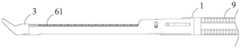
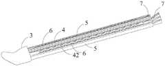
图6是本实用新型一实施例的钉仓组件与推钉片配合的结构示意图;6 is a schematic structural diagram of the cooperation between the staple cartridge assembly and the staple push piece according to an embodiment of the present invention;
图7是图6中去除一侧限位件后的结构示意图;Fig. 7 is the structural representation after removing one side limiter in Fig. 6;
图8和图9是图7中B处放大图;Figure 8 and Figure 9 are enlarged views at B in Figure 7;
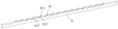
图10是本实用新型一实施例的钉带的结构示意图;10 is a schematic structural diagram of a nail strip according to an embodiment of the present invention;
图11是本实用新型一实施例的连杆的结构示意图;11 is a schematic structural diagram of a connecting rod according to an embodiment of the present invention;
图12为本实用新型另一实施例中将凸块设于钉仓盖上的结构示意图;FIG. 12 is a schematic structural diagram of disposing bumps on the nail magazine cover in another embodiment of the present invention;
图13为图12的爆炸图。FIG. 13 is an exploded view of FIG. 12 .
附图标记:Reference number:
1 钉仓组件架 6 连杆1 staple
2 钉砧组件 61 第一实施例凸块2
3 固定件 611 凸块的远端侧面3 Distal side of
4 钉带 612 配合口4 Nail with 612 Mating Port
41 吻合钉 613 凸块的近端侧面41
411 穿刺端 7 推钉块411
412 连接端 71 离断部412
42 钉带本体 8 推刀杆42
421 凸块容纳口 81 切刀421 Boss accommodating opening 81 Cutter
5 限位件 9 本体5 Stopper 9 Body
15 钉仓盖15 Nail compartment cover
16 出钉口16 nail outlet
17 第二实施例凸块17 Second Embodiment Bumps
具体实施方式Detailed ways
现在将参考附图更全面地描述示例实施方式。然而,示例实施方式能够以多种形式实施,且不应被理解为限于在此阐述的实施方式;相反,提供这些实施方式使得本实用新型将全面和完整,并将示例实施方式的构思全面地传达给本领域的技术人员。在图中相同的附图标记表示相同或类似的结构,因而将省略对它们的重复描述。Example embodiments will now be described more fully with reference to the accompanying drawings. Example embodiments, however, can be embodied in various forms and should not be construed as limited to the embodiments set forth herein; rather, these embodiments are provided so that this disclosure will be thorough and complete, and will fully convey the concept of example embodiments conveyed to those skilled in the art. The same reference numerals in the drawings denote the same or similar structures, and thus their repeated descriptions will be omitted.
为了解决现有技术中的技术问题,本实用新型提供了一种用于医用吻合器的钉仓组件以及包括该钉仓组件的医用吻合器。所述钉仓组件包括至少一个钉带和多个凸块,所述钉带包括沿所述医用吻合器的轴向方向延伸的钉带本体,所述钉带本体上设置有至少一排沿所述钉带本体的延伸方向依次排布的吻合钉,所述吻合钉通过其连接端连接至所述钉带本体;所述凸块与所述吻合钉一一对应,所述凸块位于所对应的吻合钉的连接端的远端侧,且所述吻合器击发时,所述吻合钉的连接端与所述凸块相接触,以断开与所述钉带本体的连接,从而使得所述吻合钉从所述钉带本体脱离。In order to solve the technical problems in the prior art, the present invention provides a staple cartridge assembly for a medical stapler and a medical stapler including the staple cartridge assembly. The staple cartridge assembly includes at least one staple band and a plurality of protrusions, the staple band includes a staple band body extending along the axial direction of the medical stapler, and at least one row along the staple band body is provided on the staple band body. The staples are arranged in sequence in the extension direction of the staple band body, the staples are connected to the staple band body through their connecting ends; the protruding blocks are in one-to-one correspondence with the staples, and the protruding blocks are located in The distal side of the connecting end of the staple, and when the stapler is fired, the connecting end of the staple is in contact with the projection to break the connection with the staple band body, thereby allowing the anastomosis to be The staples are disengaged from the staple strip body.
本实用新型通过将吻合钉形成于一钉带上,安装时可以直接以钉带为整体安装到钉仓组件中,钉仓组件更加方便操作。吻合钉通过其连接端连接至钉带本体,为了实现手术时吻合钉更方便地脱离钉带本体,在钉带本体上还有与钉带本体分体或一体设置的凸块。在医生握持操作把手而击发吻合器时,推钉块会从近端侧向远端侧运动,进而推动所述吻合钉闭合成型,所述吻合钉成型后,所述吻合钉的连接端与凸块相接触,在推钉块向远端侧的推力和凸块的接触力的作用下,所述吻合钉的连接端与所述钉带本体脱离,从而使得所述吻合钉可以从钉仓组件中脱离。In the utility model, the staples are formed on a staple belt, the staple belt can be directly installed into the staple cartridge assembly as a whole during installation, and the staple cartridge assembly is more convenient to operate. The staples are connected to the staple band body through their connecting ends. In order to make the staples more easily separated from the staple band body during surgery, the staple band body also has projections that are separate or integrated with the staple band body. When the doctor holds the operating handle and fires the stapler, the pusher block will move from the proximal side to the distal side, thereby pushing the staples to be closed and formed. After the staples are formed, the connecting ends of the staples and The protrusions are in contact, and under the action of the pushing force of the pusher block to the distal side and the contact force of the protrusions, the connecting ends of the staples are disengaged from the staple belt body, so that the staples can be removed from the staple cartridge disengaged from the component.
下面结合图1~11介绍本实用新型一实施例的钉仓组件和医用吻合器的结构。The structures of the staple cartridge assembly and the medical stapler according to an embodiment of the present invention will be described below with reference to FIGS. 1 to 11 .
如图1~5所示,在该实施例中,医用吻合器包括位于远端侧的钉仓组件架1和钉砧2,钉仓组件架1中安装有钉仓组件,钉仓组件架1的近端侧连接至吻合器本体9。所述钉仓组件包括两个钉带4和多个凸块61,所述钉带4包括沿所述医用吻合器的轴向方向延伸的钉带本体42,所述钉带本体42上设置有两排沿所述钉带本体42的延伸方向依次排布的吻合钉41,所述吻合钉41通过其连接端412连接至所述钉带本体42。所述凸块61与吻合钉41一一对应。在优选的实施例中,凸块61设置于连杆6。所述凸块61位于所对应的吻合钉41的连接端412的远端侧。所述钉带本体42的一侧设置有所述吻合钉41,所述钉带本体42的另一侧为朝向所述钉砧组件2的钉仓组件面,即在图3的视角中,钉带本体42的上表面为钉仓组件面,下表面设置有所述吻合钉41。As shown in FIGS. 1 to 5 , in this embodiment, the medical stapler includes a staple
钉仓组件架1的近端侧设置有推刀杆8和推钉块7,推刀杆8的远端侧设置有切刀81。两个钉带之间形成有供所述切刀81穿过的切刀槽。在医生握持操作把手(图中未示出)击发吻合器时,推刀杆8推动推钉块7向吻合器的远端侧运动,推钉块7依次与所述吻合钉41接触,并推动所述所述吻合钉41而使得所述吻合钉41向所述钉砧方向旋转运动时,所述吻合钉41的连接端412与所述凸块61相接触,在所述推钉块7的推力和所述凸块61的接触力的作用下,断开吻合钉41的连接端412与钉带本体42之间的连接,使所述吻合钉41从所述钉带本体42脱离。The proximal end side of the
在本实用新型中,远端侧和近端侧是相对于操作者来说的,其中,远端侧指的是距离操作者较远的一端,近端侧指的是距离操作者较近的一端。例如,在图1的视角中,钉仓组件架1的远端侧指的是图中左边一端,近端侧指的是图中右边一端,钉砧2的远端侧指的是图中左边一端,近端侧指的是图中右边一端。医用吻合器的轴向方向指的是从医用吻合器的近端侧指向远端侧的方向,即图2中钉带本体42延伸的方向。对于一个部件来说,其内侧指的是相对于其外侧来说更靠近所述吻合器的轴心的一侧。In the present invention, the distal side and the proximal side are relative to the operator, wherein the distal side refers to the end that is farther from the operator, and the proximal side refers to the end that is closer to the operator. one end. For example, in the perspective of FIG. 1 , the distal side of the staple
在该实施例中,每条钉带4的所述钉带本体42分别设置有两排所述吻合钉41,且两排所述吻合钉41沿所述钉带本体42的延伸方向交错设置;与所述吻合钉41相对应地,同一钉带4的两排凸块61沿所述钉带本体42的延伸方向交错设置。在本实用新型中,钉带4的数量和吻合钉41的排数不以此实施例为限,在其他可替代的实施方式中,可以减少或增多钉带4的数量,可以减少或增多吻合钉41的排数,均属于本实用新型的保护范围之内。In this embodiment, the
在该实施例中,钉仓组件包括远端侧的固定件3、限位件5、连杆6及钉带4,钉仓组件的近端侧还设有推钉块7。在一种生产工艺中,固定件3与限位件5及连杆6采用注塑工艺,限位件5及连杆6是嵌入固定件3进行注塑的;然后再进行装入钉仓组件,钉仓组件的近端侧与连杆6的近端侧焊接。在另外一种工艺中,固定件3与连杆6也可以是分别设置,后连接在一起;然后装钉带4。所述钉带4的远端侧固定于所述固定件3上。所述钉带4的远端侧与所述固定件3的连接可以是不可拆卸的连接,也可以是可拆卸的连接。如图5所示,为了限定所述吻合钉41的出钉方向,每排所述钉带4的两侧还分别设置有限位件5及连杆6,所述限位件5及所述连杆6沿所述医用吻合器的轴向方向延伸,两个钉带4的两个内侧的限位件5之间限定所述切刀槽。限位件5和所述连杆6共同限定吻合钉41的容纳空间和出钉方向,避免吻合钉41在钉仓组件中发生错位或出钉时方向偏离而卡钉的情况。在该实施例中,每条钉带4的轴向方向两侧均由所述限位件5及所述连杆6限位,即每一颗吻合钉41的在沿轴向方向的两侧都有所述限位件5或所述连杆6限位,防止吻合钉41在从钉仓组件中向组织运动时,向钉仓组件的内侧或者外侧偏离,即所述吻合钉在所述限位件5及所述连杆6限位的作用下,只能沿着轴向运动,而不能有偏离轴向的偏摆。所述吻合钉41还包括穿刺端411,穿刺端411位于远离连接端412的一端,在击发所述吻合器时,所述吻合钉41的穿刺端411在推钉块7的作用下,向钉砧组件运动,并从限位件5和连杆6之间限定的空间中穿出,进入组织,在钉砧组件2的钉砧面成型。In this embodiment, the staple cartridge assembly includes a distal
在其他可选的实施方式中,所述凸块61和所述钉带本体42可以是一体设置的,例如,将所述凸块61形成于所述钉带本体42的钉仓组件面上,或者将凸块61焊接于所述钉带本体42的钉仓组件面上。In other optional embodiments, the
在该实施例中,凸块61与钉带本体42也可以是分体设置的。如图6~11所示,两排所述吻合钉41之间设置有一连杆6,所述连杆6的顶部设置有所述凸块61即所述凸块61设于所述连杆6靠近钉仓组件的钉仓面的一侧。所述凸块61从所述钉带本体42的一侧边向上伸出。为了更清楚地示出钉带4和连杆6的配合结构,在图7中省去了最外侧的一个限位件5。进一步地,所述钉带本体42与各个所述凸块61对应的位置分别开设有用于容纳所述凸块61的凸块容纳口421。凸块61从凸块容纳口421中穿出而突出于所述钉仓组件面。连杆6也可以和限位件5共同限定吻合钉41的容纳空间和出钉方向。吻合钉41在被击发时,两侧同时受到限位件5的侧面引导和连杆6的侧面引导,可以顺畅地从钉带本体42表面的开口中穿出,而不会发生偏离轴向方向的偏摆而造成卡钉现象。其中,限位件5和连杆6优选采用比较硬的金属,例如不锈钢等制成。In this embodiment, the
由于现有技术中采用单个吻合钉的结构中,每个吻合钉是单独安装在一个钉孔里面的,其不会存在吻合钉的定位问题。而在采用钉带4的结构中,由于不再设置单独的每个钉孔,因此,需要进一步解决钉带4中吻合钉41的定位问题。如图8所示,在该实施例中,连杆6还可以与限位件5一起限定吻合钉41在钉仓组件中的位置。即每排吻合钉41设置于其一侧的限位件5和一侧的连杆6之间。每两个相邻的连杆6和限位件5一起限定了一个沿吻合器轴向方向的吻合钉容纳空间。吻合钉41的上下运动只能限定在此吻合钉容纳空间中,既不会向限位件5的一侧偏离,也不会向连杆6的一侧偏离。在吻合钉41向钉仓组件面运动而与钉带本体42脱离的过程中,吻合钉41的运动方向也被连杆6和限位件5而限定,可以准确地定位到组织上需要吻合的位置。Since in the prior art structure using a single staple, each staple is individually installed in a staple hole, there is no problem of staple positioning. However, in the structure using the
因此,该实施例不仅解决了手术时钉带4中吻合钉41方便脱离的问题,还进一步解决了钉带4中吻合钉41定位的问题。Therefore, this embodiment not only solves the problem of convenient disengagement of the
在该实施例中,所述凸块61的远端侧面611为从远端侧向近端侧逐渐上升的斜面,且所述远端侧面611整体呈顺滑设置,即远端侧面611的顶端平滑过渡至凸块61的顶面,例如在远端侧面611和凸块61的顶面之间设有顺滑的倒角,以防止在吻合器闭合时,锋利的边角对组织造成损伤。所述凸块61与所述远端侧面611相对的近端侧面613,即与所述连接端412相邻的近端侧面613,也设为从远端侧向近端侧逐渐上升的斜面,以提高与连接端412的配合效果。进一步地,近端侧面613可以形成为刃口,以加强对连接端412的剪切效果。在一优选的实施方式中,在初始状态下,所述连接端412与所述近端侧面613之间设有一定的间隔,以保证所述吻合钉41在旋转的过程中的形变,不会受到所述近端侧面613的阻挡,并且保证所述吻合钉未完全成型之前,不与钉带分离。In this embodiment, the
如图8~11所示,所述凸块61的近端侧开设有一配合口612,所述吻合钉41的连接端412具有一连接梁,且所述连接梁位于所述配合口612中,即在由近端侧朝向远端侧的方向上,所述凸块61至少部分与所述连接端412重合,以增大在吻合钉脱离钉带4时吻合钉41的连接端412与凸块61的接触面积。在该实施例中,推钉块7为楔形的推钉块7,且推钉块7具有与吻合钉41的连接端412相对应的离断部71。如图9所示,在击发所述吻合器时,推钉块7在推刀杆8的作用下向远端侧方向推动吻合钉,即推钉块7以图9中C方向运动,所述吻合钉41受到推钉块7向吻合器远端侧方向的推力,吻合钉41的穿刺端411向钉砧组件2运动,吻合钉41的穿刺端411以连接端412为轴向钉砧组件2旋转,旋转方向如图9中的D方向所示,连接梁与凸块61的近端侧面接触,连接梁给凸块61一个向吻合器远端侧方向的力,凸块61给连接梁一个沿图9中E方向的反作用力,从而在凸块61处离断吻合钉41的连接梁,使得吻合钉41与钉带4脱离,吻合钉41在钉砧组件2的钉砧面处成形,以吻合组织,同时切刀81在切刀槽中从近端侧向远端侧运动,以离断组织,从而实现组织的吻合和切断。As shown in FIGS. 8-11 , a
如图12和图13所示,示出了本实用新型另一实施例的钉仓组件的结构。该实施例中与前一实施例的区别在于,凸块61并不是设置在连杆上的,而是设置在钉仓盖13上的。如图12所示,所述钉仓组件还包括钉仓盖15,所述钉仓盖15覆盖于所述钉带本体42的上表面,所述钉仓盖15上开设有与所述吻合钉41一一对应的出钉口16。在吻合钉41吻合时,吻合钉41的穿刺端411从出钉口16中朝向钉砧组件2伸出。所述钉仓盖15的出钉口16处设置有所述凸块61,所述凸块61突出于所述钉仓盖15的下表面而朝向所述吻合钉41伸出。As shown in FIG. 12 and FIG. 13 , the structure of the staple cartridge assembly according to another embodiment of the present invention is shown. The difference between this embodiment and the previous embodiment is that the
本实用新型所提供的钉仓组件及包括其的医用吻合器具有如下优点:The staple cartridge assembly provided by the present utility model and the medical stapler comprising the same have the following advantages:
本实用新型提供了一种用于医用吻合器的钉仓组件,将吻合钉形成于一钉带上,安装和更换更加方便,在一次手术完成后,可以只更换钉带;在钉带本体上设置凸块,方便吻合钉与钉带本体的脱离,保证手术过程中吻合钉可以脱离钉仓组件而将组织吻合,从而避免手术中出现卡钉的情况,提高手术效果。The utility model provides a staple cartridge assembly for a medical stapler. The staples are formed on a staple belt, which is more convenient for installation and replacement. After one operation is completed, only the staple belt can be replaced; The protruding block is arranged to facilitate the detachment of the staples from the staple belt body, to ensure that the staples can be separated from the staple cartridge assembly and anastomosed to the tissue during the operation, thereby avoiding staple jamming during the operation and improving the surgical effect.
以上内容是结合具体的优选实施方式对本实用新型所作的进一步详细说明,不能认定本实用新型的具体实施只局限于这些说明。对于本实用新型所属技术领域的普通技术人员来说,在不脱离本实用新型构思的前提下,还可以做出若干简单推演或替换,都应当视为属于本实用新型的保护范围。The above content is a further detailed description of the present invention in conjunction with specific preferred embodiments, and it cannot be considered that the specific implementation of the present invention is limited to these descriptions. For those of ordinary skill in the technical field of the present invention, without departing from the concept of the present invention, some simple deductions or substitutions can be made, which should be regarded as belonging to the protection scope of the present invention.
Claims (16)
Translated fromChinesePriority Applications (1)
| Application Number | Priority Date | Filing Date | Title |
|---|---|---|---|
| CN201920474022.XUCN209996391U (en) | 2019-04-09 | 2019-04-09 | Staple cartridge assembly and medical stapler including the same |
Applications Claiming Priority (1)
| Application Number | Priority Date | Filing Date | Title |
|---|---|---|---|
| CN201920474022.XUCN209996391U (en) | 2019-04-09 | 2019-04-09 | Staple cartridge assembly and medical stapler including the same |
Publications (1)
| Publication Number | Publication Date |
|---|---|
| CN209996391Utrue CN209996391U (en) | 2020-01-31 |
Family
ID=69303302
Family Applications (1)
| Application Number | Title | Priority Date | Filing Date |
|---|---|---|---|
| CN201920474022.XUWithdrawn - After IssueCN209996391U (en) | 2019-04-09 | 2019-04-09 | Staple cartridge assembly and medical stapler including the same |
Country Status (1)
| Country | Link |
|---|---|
| CN (1) | CN209996391U (en) |
Cited By (3)
| Publication number | Priority date | Publication date | Assignee | Title |
|---|---|---|---|---|
| CN111513784A (en)* | 2020-05-19 | 2020-08-11 | 微至(苏州)医疗科技有限公司 | Olecranon type auxiliary anastomat under mirror |
| CN111789645A (en)* | 2019-04-09 | 2020-10-20 | 苏州天臣国际医疗科技有限公司 | Staple cartridge assembly and medical stapler including the same |
| WO2023036222A1 (en)* | 2021-09-09 | 2023-03-16 | 天臣国际医疗科技股份有限公司 | Staple cartridge assembly and medical stapler |
- 2019
- 2019-04-09CNCN201920474022.XUpatent/CN209996391U/ennot_activeWithdrawn - After Issue
Cited By (6)
| Publication number | Priority date | Publication date | Assignee | Title |
|---|---|---|---|---|
| CN111789645A (en)* | 2019-04-09 | 2020-10-20 | 苏州天臣国际医疗科技有限公司 | Staple cartridge assembly and medical stapler including the same |
| CN111789645B (en)* | 2019-04-09 | 2025-03-25 | 天臣国际医疗科技股份有限公司 | Nail cartridge assembly and medical stapler including the same |
| CN111513784A (en)* | 2020-05-19 | 2020-08-11 | 微至(苏州)医疗科技有限公司 | Olecranon type auxiliary anastomat under mirror |
| WO2023036222A1 (en)* | 2021-09-09 | 2023-03-16 | 天臣国际医疗科技股份有限公司 | Staple cartridge assembly and medical stapler |
| CN115919393A (en)* | 2021-09-09 | 2023-04-07 | 天臣国际医疗科技股份有限公司 | Staple cartridge components and medical staplers |
| CN115919393B (en)* | 2021-09-09 | 2024-05-28 | 天臣国际医疗科技股份有限公司 | Nail bin assembly and medical anastomat |
Similar Documents
| Publication | Publication Date | Title |
|---|---|---|
| US11812963B2 (en) | Surgical stapler with partial pockets | |
| CN111789645A (en) | Staple cartridge assembly and medical stapler including the same | |
| US8397972B2 (en) | Shipping wedge with lockout | |
| CN209996391U (en) | Staple cartridge assembly and medical stapler including the same | |
| US9655615B2 (en) | Active wedge and I-beam for surgical stapler | |
| US20180125495A1 (en) | Stapling device with self-releasing knife carrier pusher | |
| JP2016516529A (en) | Active wedge and I-beam for a surgical stapler | |
| CN111789644B (en) | Nail cartridge assembly and medical stapler including the same | |
| EP2992832B1 (en) | Devices for facilitating ejection of surgical fasteners from cartridges | |
| CN106923874B (en) | a surgical stapler | |
| CN115137425A (en) | Nail bin assembly and surgical instrument | |
| CN210871799U (en) | Staple cartridge assembly and medical stapler including the same | |
| CN209996390U (en) | Staple cartridge assembly and medical stapler including the same | |
| CN211049481U (en) | Anvil and medical stapler including the same | |
| CN209996388U (en) | Anvil and medical stapler including the same |
Legal Events
| Date | Code | Title | Description |
|---|---|---|---|
| GR01 | Patent grant | ||
| GR01 | Patent grant | ||
| AV01 | Patent right actively abandoned | Granted publication date:20200131 Effective date of abandoning:20250325 | |
| AV01 | Patent right actively abandoned | Granted publication date:20200131 Effective date of abandoning:20250325 | |
| AV01 | Patent right actively abandoned | ||
| AV01 | Patent right actively abandoned |