CN209884262U - Thrombus taking device - Google Patents
Thrombus taking deviceDownload PDFInfo
- Publication number
- CN209884262U CN209884262UCN201822119356.3UCN201822119356UCN209884262UCN 209884262 UCN209884262 UCN 209884262UCN 201822119356 UCN201822119356 UCN 201822119356UCN 209884262 UCN209884262 UCN 209884262U
- Authority
- CN
- China
- Prior art keywords
- thrombus
- thrombectomy
- removal
- distal end
- plug removal
- Prior art date
- Legal status (The legal status is an assumption and is not a legal conclusion. Google has not performed a legal analysis and makes no representation as to the accuracy of the status listed.)
- Active
Links
Images


Landscapes
- Surgical Instruments (AREA)
Abstract
Translated fromChinese
Description
Translated fromChinese技术领域technical field
本实用新型涉及介入医疗领域,具体涉及一种取栓器。The utility model relates to the field of interventional medicine, in particular to a thrombectomy device.
背景技术Background technique
急性缺血性卒中(acute ischemic stroke,AIS)是脑部血流的突然阻塞而引起局部脑组织缺血坏死所导致的神经组织损伤。急性缺血性脑卒中是卒中最常见的类型,也是中老年人致死和致残的主要疾病。尤其是大血管闭塞所致的急性脑卒中,病情凶险,死亡率、致残率高。一旦发生中风,给患者造成巨大身心危害,也给患者家庭及社会造成沉重的负担。Acute ischemic stroke (AIS) is a sudden blockage of cerebral blood flow, resulting in the damage of nerve tissue caused by ischemic necrosis of local cerebral tissue. Acute ischemic stroke is the most common type of stroke and a major cause of death and disability among middle-aged and elderly people. Especially acute cerebral apoplexy caused by large vessel occlusion is dangerous, with high mortality and disability rate. Once a stroke occurs, it will cause huge physical and mental harm to the patient, and also cause a heavy burden to the patient's family and society.
血管的再通是治疗急性缺血性脑卒中的关键。目前治疗急性缺血性脑卒中的常规方法包括两大类:介入溶栓和机械取栓。Vascular recanalization is the key to the treatment of acute ischemic stroke. The current conventional methods for the treatment of acute ischemic stroke include two categories: interventional thrombolysis and mechanical thrombectomy.
介入溶栓是利用导管把溶栓剂注入到病变所在的血管内的病灶附近,在病灶局部瞬间形成高浓度的溶栓剂,加速血栓溶解,进而增加血管再通的机会。一般静脉溶栓应在发病3小时内进行,动脉溶栓时间窗在6小时内,且仅约5%左右的脑卒中患者能够接受溶栓治疗;并且溶栓治疗血管再通时间长,溶栓后症状性颅内出血率高。此外,溶栓治疗只适合于体积较小的血栓,对大体积血栓效果不明显,在急性大脑动脉脑梗死中,如果血栓长度超过8mm,溶栓几乎不能使阻塞的血管再通,即便是能够再通,再次堵塞的概率也很大。Interventional thrombolysis is the use of a catheter to inject a thrombolytic agent into the vicinity of the lesion in the blood vessel where the lesion is located, and a high concentration of thrombolytic agent is instantly formed locally in the lesion to accelerate the dissolution of the thrombus, thereby increasing the chance of vascular recanalization. Generally, intravenous thrombolysis should be carried out within 3 hours of onset, and the time window of arterial thrombolysis is within 6 hours, and only about 5% of stroke patients can receive thrombolysis; Post-symptomatic intracranial hemorrhage rate is high. In addition, thrombolytic therapy is only suitable for small thrombus, and the effect on large thrombus is not obvious. In acute cerebral arterial infarction, if the length of the thrombus exceeds 8 mm, thrombolysis can hardly recanalize the blocked blood vessel, even if it can Re-opening, the probability of blocking again is also very high.
为了解决上述问题,对于超过溶栓时间窗和有溶栓治疗禁忌症的患者,可采用机械取栓的方法清除血栓,此方法能够快速使闭塞的血管再通,提高血管再通率,减少溶栓药物剂量,降低症状性脑出血的发生率,延长治疗时间窗,缩短再通时间,从而为可逆的缺血脑组织争取更多的时间,明显改善患者的预后。In order to solve the above problems, for patients who have exceeded the thrombolysis time window and have contraindications to thrombolysis, the method of mechanical thrombectomy can be used to remove the thrombus. The dose of thrombus drugs can reduce the incidence of symptomatic cerebral hemorrhage, prolong the treatment time window, and shorten the recanalization time, so as to gain more time for reversible ischemic brain tissue and significantly improve the prognosis of patients.
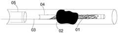
目前用于机械取栓的取栓器一般包括取栓支架。如图1所示,使用前将取栓支架收束与微导管04内;使用时将微导管04与取栓支架01一起穿过血栓02,使取栓支架01靠近近端的位置位于血栓02内;回撤微导管04至回收导管05内,取栓支架01在没有微导管04的束缚后膨胀;稍等几分钟,使取栓支架01的支架杆嵌入血栓02内;再向近端拉动导丝03,将取栓支架01与血栓02一并收入至回收导管05内,将血栓02从血管内取出。在此过程中,血栓易碎,形成的血栓碎片极易造成二次栓塞;此外,因为颅内血管迂曲且血管壁薄,现有技术的取栓器也没有解决如何在不损伤颅内迂曲血管的同时有效避免血栓碎片造成二次栓塞的问题。The thrombectomy devices currently used for mechanical thrombectomy generally include thrombectomy stents. As shown in Figure 1, before use, the thrombectomy stent is bundled into the
实用新型内容Utility model content
本实用新型提供了一种取栓器,包括包括导丝和第一取栓部,所述导丝与所述第一取栓部近端相连,还包括第二取栓部和连接部,所述第一取栓部的远端与所述第二取栓部的近端之间通过连接部相连,所述连接部为柔性结构。The utility model provides a thrombus removal device, which comprises a guide wire and a first plug removal part, the guide wire is connected with the proximal end of the first plug removal part, and further comprises a second plug removal part and a connecting part, so that the The distal end of the first plug removal part and the proximal end of the second plug removal part are connected by a connection part, and the connection part is a flexible structure.
在一实施例中,所述第二取栓部为开口朝向远端的锥形结构。In one embodiment, the second bolt removal portion is a tapered structure with an opening facing the distal end.
在一实施例中,所述第一取栓部包括由管体切割成多段切割杆构成的网状结构。In one embodiment, the first bolt-removing portion includes a net-like structure formed by cutting a tubular body into multiple sections of cutting rods.
在一实施例中,所述第二取栓部为由编织丝编织而成的网状结构,所述编织丝的丝径小于所述切割杆的宽度。In one embodiment, the second bolt-removing portion is a mesh structure woven from braided wires, and the wire diameter of the braided wires is smaller than the width of the cutting rod.
在一实施例中,所述第一取栓部的网孔面积为1.0~3.5mm2,所述第二取栓部的网孔面积为0.01~2.0mm2。In one embodiment, the mesh area of the first bolt-removing portion is 1.0-3.5 mm2 , and the mesh area of the second bolt-removing portion is 0.01-2.0 mm2 .
在一实施例中,所述第二取栓包括多个向外辐射的支撑杆和覆膜,所述覆膜围设于所述支撑杆上构成所述锥形结构,所述覆膜上设有孔。In one embodiment, the second bolt removal includes a plurality of supporting rods radiating outward and a coating film, the coating film is surrounded on the supporting rods to form the tapered structure, and the coating film is provided on the There are holes.
在一实施例中,所述孔的孔径为0.001~0.2mm。In one embodiment, the diameter of the hole is 0.001˜0.2 mm.
在一实施例中,所述第一取栓部远端端部聚拢于所述连接部的近端。In one embodiment, the distal end of the first bolt-retrieving portion is gathered at the proximal end of the connecting portion.
在一实施例中,所述第一取栓部近端通过至少两根对称设置的近端连杆与所述导丝远端相连。In one embodiment, the proximal end of the first thrombectomy portion is connected to the distal end of the guide wire through at least two symmetrically arranged proximal connecting rods.
在一实施例中,所述第一取栓部的长度为15~60mm;所述第二取栓部近端的锥度为30°~60°,所述第二取栓部远端的半径为0.5~3mm。In one embodiment, the length of the first bolt-removing portion is 15-60 mm; the taper of the proximal end of the second bolt-removing portion is 30°-60°, and the radius of the distal end of the second bolt-removing portion is 0.5~3mm.
本实用新型的取栓器通过设置第一取栓部和第二取栓部,以及在二者之间起连接作用的柔性连接部,很好地解决了现有技术取栓器取栓时血栓碎片造成二次栓塞的问题,同时解决了颅内血管迂曲且血管壁薄易受损的问题,保证第一取栓部取栓后产生的血栓碎片能被第二取栓部顺利取出,且取栓过程中不会对血管造成损伤。The thrombectomy device of the utility model is provided with a first thrombectomy part and a second thrombectomy part, and a flexible connecting part that connects the two, so that the thrombus removal device of the prior art can well solve the problem of thrombus removal in the prior art thrombectomy device. The problem of secondary embolism caused by fragments is solved, and the problem of tortuosity of intracranial blood vessels and thin and easily damaged blood vessel walls is solved, ensuring that the thrombus fragments generated after thrombectomy by the first thrombectomy part can be successfully removed by the second thrombectomy part, and the thrombus fragments are removed. Blood vessels will not be damaged during the embolization process.
附图说明Description of drawings
图1为现有技术的取栓器位于血管内进行取栓时示意图;Fig. 1 is a schematic diagram when a prior art thrombectomy device is positioned in a blood vessel for thrombectomy;
图2为本实用新型一实施例的取栓器结构示意图,包括第一取栓部和第二取栓部;2 is a schematic structural diagram of a thrombus removal device according to an embodiment of the present invention, including a first stud removal part and a second stud removal part;
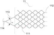
图3为图2中第一取栓部结构示意图;3 is a schematic structural diagram of the first bolt-removing portion in FIG. 2;
图4为图3的第一取栓部沿长度方向展开结构示意图;FIG. 4 is a schematic view of the expanded structure of the first bolt-removing portion of FIG. 3 along the length direction;
图5为图2中第二取栓部结构示意图;FIG. 5 is a schematic structural diagram of the second bolt-removing portion in FIG. 2;
图6为本实用新型另一实施例的取栓器中第二取栓部结构示意图;FIG. 6 is a schematic structural diagram of a second bolt-removing portion in a bolt-retriever according to another embodiment of the present invention;
图7为利用本实用新型的取栓器在迂曲血管内取栓时示意图。FIG. 7 is a schematic diagram of using the thrombectomy device of the present invention to remove thrombus from a tortuous blood vessel.
具体实施方式Detailed ways
为更好地理解本实用新型的技术方案和有益效果,以下结合附图对本实用新型做举例说明。In order to better understand the technical solutions and beneficial effects of the present utility model, the present utility model is exemplified below with reference to the accompanying drawings.
在介入医疗领域,定义靠近操作者的一端为“近端”,远离操作者的一端为“远端”。In the field of interventional medicine, the end close to the operator is defined as the "proximal end", and the end away from the operator is defined as the "distal end".
如图2所示,本实施例的取栓器10整体为可压缩和可膨胀的长形结构。第一取栓部11被压缩时,整体体积减小,可被收入至较小的导管内;当失去外部径向力的束缚时,第一取栓部11可膨胀成体积较大的柱体结构。第一取栓部11包括导丝13、第一取栓部11和第二取栓部12以及连接部14。导丝13与第一取栓部12近端相连。第一取栓部11的远端和第二取栓部12的近端之间通过连接部14相连。导丝13为具有一定刚度的丝线结构,用于将取栓器10输送至目标取栓位置,或将取栓器10从血管内撤出。第一取栓部11和导丝之间可通过焊接、胶接、卯接、压接等方式连接。As shown in FIG. 2 , the
自然状态下,第一取栓部11为具有一定长度的网状结构。如图3和图4所示,本实施例的第一取栓部11为由一段管体切割成多段切割杆111相连构成的网状结构。网状结构的网孔形状可以为任意形状,如菱形、三角形、圆形等。网状结构的远端为多个周向设置的直形远端连杆112,多个远端连杆112束起使第一取栓部11的远端形成封闭端。同时,束起后的远端连杆112也方便与连接部14相连。In a natural state, the first bolt-removing
为达到良好的取栓效果,第一取栓部11应具有一定的径向力。径向力的控制可通过选择适合的切割管体的厚度、切割杆11的宽度以及网状结构的网孔面积(即网孔的疏密)来实现。若管体厚度过小或切割杆11宽度过小或网孔面积过大,切割后网状结构的径向力过小,切割杆111难以穿透血栓块进入其中;若管体厚度过大或切割杆宽度过大或网孔面积过小,第一取栓部11又难以压缩收至微导管内进行输送。因此,管体的厚度可选为0.05~0.5mm;切割杆111的宽度可选为0.04~0.20mm;网状结构的网孔面积可为1.0~3.5mm2。In order to achieve a good bolt-removing effect, the first bolt-removing
第一取栓部11整体长度可为15~60mm,当第一取栓部11的长度小于15mm时,取栓效果不理想,无法取出长度大于15mm的血栓;若长度大于60mm,第一取栓部11较易损伤血管内壁。自然状态下,第一取栓部11呈管状,为保证取栓器使用时不对血管造成损伤,第一取栓部11的最大直径可为2~6mm。The overall length of the
为使第一取栓部11更好地从微导管内推出或收入,第一取栓部11还包括在网状结构的近端对称设置的至少两根近端连杆113。两根近端连杆113的近端相互靠近后连接在一起,形成角度A。第一取栓部11处于自然状态下的角度A的范围可以为30°~120°。同时,为防止近端连杆113由于受到推出力和微导管的摩擦力而使切割杆111折弯,近端连杆113的宽度应大于切割杆111的宽度,近端连杆113的宽度可为0.1~0.3mm。可以理解的是,在其它实施例中,近端连杆的数量可以大于两根,且优选为环绕切割杆形成的网状结构的近端均匀设置。In order to make the first
为方便观察第一取栓部10位于体内时近端的具体位置,第一取栓部11的近端还可以设有显影结构114。显影结构114可由原子质量比大的具有显影特性的金属材料或者稀土材料制成,可选为金、铂、铊、钽等。In order to facilitate the observation of the specific position of the proximal end of the first
第一取栓部11可由具有形状记忆特性的材料制成,如通过激光切割具有形状记忆效应和超弹性的金属管材(如NiTi合金管),然后通过模具成型,再经过热处理定型成需要的形状。可以理解的是,第一取栓部也可以首先通过切割片材或通过编织,再经过模具成型和热处理定型制作完成。更进一步地,第一取栓部的材料也可选为高弹性的高分子材料。The first bolt-removing
如图5所示,第二取栓部12为开口朝向远端的中空的锥形结构,即锥形结构的锥顶与连接部14相连,锥底为朝向远端的圆形开口。自然状态下,保证第二取栓部12远端能与血管内壁贴合,锥形结构的锥角B可为30°~60°,远端圆形开口的半径R可为0.5~3mm。远端开口的半径R需要在合适范围,保证使用时,第二取栓部不会对血管造成损伤,因此需通过选择合适的锥角B使第二取栓部12有较好的使用效果。若锥角B小于30°,第二取栓部12整体长度过长,在微导管内较难推送;若锥角大于60°,第二取栓部12难压缩进入微导管,且回收时附在第二取栓部12上的血栓碎片易被回收导管刮落。本实施例的第二取栓部12通过编织丝121编织而成。且锥形结构的近端还设有收容锥顶的微管122,微管122与连接部14远端相连。为方便观察第二取栓部12位于体内时的位置,微管122可以选用具有显影特性的材料制成。第二取栓部12的编织丝的材料可以为具有形状记忆效应和超弹性的金属丝或高弹性的高分子丝,编织完成后,再通过热定型处理固定成锥形结构。使用时,第二取栓部在血管内扩张,只有远端与血管内壁接触,为线接触,接触面积小,因此对血管的损伤也小。As shown in FIG. 5 , the second bolt-removing
可以理解的是,在其它实施例中,第二取栓部22也可以是图6所示的结构。即第二取栓部22包括多个向外辐射的呈伞状的支撑杆221和设于支撑杆221上的覆膜223。覆膜223与支撑杆221共同构成中空的锥形结构。支撑杆221的数量可选为3~12根,支撑杆221数量过多,压缩后第二取栓部22较难收入至微导管中,若支撑杆221数量过少,又难以支撑覆膜223使其远端与血管内壁贴合。覆膜223可由生物相容性材料制成,如PET。覆膜223的厚度可为0.01~0.30mm。当覆膜过厚时,第二取栓部22压缩后体积较大,难以收入微导管内进行输送;若覆膜过薄,又极易在使用过程中发生破损。同时,为方便血液通过,覆膜223上还设有孔,孔的孔径可为0.001~0.2mm。第二取栓部22的作用主要是拦截血栓碎片,若覆膜上的孔过大,则部分血栓碎片仍能从孔内通过,第二取栓部的拦截效果差;若覆膜上的孔过小,又不利于血液渗透。It can be understood that, in other embodiments, the second bolt-removing portion 22 may also be the structure shown in FIG. 6 . That is, the second bolt-removing portion 22 includes a plurality of umbrella-shaped support rods 221 radiating outward and a film 223 provided on the support rods 221 . The covering film 223 and the support rod 221 together form a hollow conical structure. The number of support rods 221 can be selected from 3 to 12. If the number of support rods 221 is too large, it is difficult to receive the second bolt-removing portion 22 into the microcatheter after compression. If the number of support rods 221 is too small, it is difficult to support the film 223 Make its distal end fit with the inner wall of the blood vessel. The cover 223 may be made of a biocompatible material, such as PET. The thickness of the coating film 223 may be 0.01-0.30 mm. When the covering film is too thick, the second plug removal part 22 has a larger volume after being compressed, and it is difficult to be transported into the microcatheter; if the covering film is too thin, it is very easy to be damaged during use. Meanwhile, in order to facilitate the passage of blood, the membrane 223 is also provided with holes, and the diameter of the holes may be 0.001-0.2 mm. The function of the second thrombectomy part 22 is mainly to intercept thrombus fragments. If the holes on the covering film are too large, some thrombus fragments can still pass through the holes, and the interception effect of the second thrombectomy part is poor; Too small, and it is not conducive to blood penetration.
可以理解的是,在其它实施例中,第二取栓部也可以是开口朝向远端其它结构,如第二取栓部的轴向截面的形状为弓形。It can be understood that, in other embodiments, the second bolt retrieval portion may also have other structures with the opening facing the distal end, for example, the shape of the axial cross-section of the second bolt retrieval portion is arcuate.
第二取栓部12与第一取栓部11不同,第二取栓部12主要功能是拦截第一取栓部11取栓时形成的血栓碎片,不需要太大的径向力去嵌入到血栓内部。因此,第二取栓部12的径向力可以小于第一取栓部11的径向力,如编织丝121的丝径小于第一取栓部11上切割杆111的宽度。参照控制第一取栓部11径向力的方法,可以将第二取栓部12的网孔面积设为0.01~2.0mm2;构成第二取栓部12的编织丝121的丝径可为0.02~0.15mm。The
连接部14为柔性结构,具体为线形结构,例如可以是柔性合金丝或多个活动的单元枢接形成的线形结构。将连接部14设置成柔性结构主要方便取栓器10在迂曲血管内行进且不对血管造成损伤。例如,当第一取栓部11与第二取栓部12所在的血管段之间存在较大弯曲时,连接部14的柔性设计可以减弱第一取栓部11与第二取栓部12之间的相互影响和制约关系,不会损伤血管内壁。连接部14的长度可选范围较大,如1~20mm,只要使取栓器输送至血管内能正常使用即可。The connecting
可以理解的是,为方便观察第一取栓部11远端,也可以在连接部14上设置与第一取栓部11上的显影结构114一样的显影结构。It can be understood that, in order to facilitate the observation of the distal end of the first plug-removing
图7示出了利用本实施例的取栓器10进入血管内进行取栓时的结构示意图。本实用新型的取栓器的使用过程与现有技术的取栓器大体上相同,首先需要将取栓器10压缩至微导管内,通过回收导管将微导管及取栓器顺着血流的方向输送至需要取栓的位置;然后将微导管连同取栓器10一起穿过血栓20,通过成像设备观察显影结构114的位置,使得第一取栓部11的近端位于血栓20的远端;接着回撤微导管,使第二取栓部12和第一取栓部11依次膨胀展开;等待几分钟,使第一取栓部11的切割杆111嵌入至血栓20内,再通过导丝13拉动取栓器10,利用第一取栓部11带动血栓20逆着血流的方向朝向近端移动,此时,血栓20上会有部分血栓碎片掉落,血栓碎片顺着血流的方向朝着第二取栓部12移动,因第二取栓部12远端与血管内壁贴合,可利用第二取栓部上的编织网(或薄膜)拦截掉落的血栓碎片;最后将第一取栓部11和第二取栓部12完全收入至回收导管内,完成取栓。当然,本实用新型的取栓器也可以配合球囊导管使用,回撤取栓器前,通过扩张的球囊导管暂时性封堵血管,取栓时,没有近端血流的冲刷,血栓碎片更少,取栓效果更好。FIG. 7 shows a schematic structural diagram of using the
利用本实用新型的取栓器进行取栓时,不仅能利用第二取栓器很好地解决现有技术取栓器取栓时血栓碎片造成二次栓塞的问题,且第二取栓部与血管壁之间为线接触,接触面小,对血管损伤小;同时也通过柔性连接部解决了颅内血管迂曲且血管壁薄易受损的问题,保证第一取栓部取栓后产生的血栓碎片能被第二取栓部顺利取出,且取栓过程中不会对血管造成损伤。When using the thrombectomy device of the utility model for thrombectomy, not only can the second thrombectomy device be used to solve the problem of secondary embolism caused by thrombus fragments during thrombectomy in the prior art thrombectomy device, but also the second thrombectomy part is connected to the thrombectomy device. The blood vessel walls are in line contact, with a small contact surface and little damage to the blood vessels. At the same time, the flexible connection part solves the problem of the tortuous intracranial blood vessels and the thin and easily damaged blood vessel walls, ensuring that the first thrombectomy part is used to remove the thrombus. The thrombus fragments can be successfully removed by the second thrombectomy part, and the blood vessel will not be damaged during the thrombectomy process.
可以理解的是,上述具体实施方式仅为部分优选实施例,并非对本实用新型的限制,本领域技术人员可以根据实际需求对部分结构做简单替换,在不脱离本实用新型构思的前提下的做的非实质性改变均在本实用新型保护范围之内,本实用新型的保护范围以权利要求为准。It can be understood that the above-mentioned specific embodiments are only some preferred embodiments, and are not intended to limit the present invention. Those skilled in the art can simply replace some of the structures according to actual needs, without departing from the concept of the present invention. The non-substantial changes of the present invention are all within the protection scope of the present invention, and the protection scope of the present invention is subject to the claims.
Claims (10)
Translated fromChinesePriority Applications (1)
| Application Number | Priority Date | Filing Date | Title |
|---|---|---|---|
| CN201822119356.3UCN209884262U (en) | 2018-12-17 | 2018-12-17 | Thrombus taking device |
Applications Claiming Priority (1)
| Application Number | Priority Date | Filing Date | Title |
|---|---|---|---|
| CN201822119356.3UCN209884262U (en) | 2018-12-17 | 2018-12-17 | Thrombus taking device |
Publications (1)
| Publication Number | Publication Date |
|---|---|
| CN209884262Utrue CN209884262U (en) | 2020-01-03 |
Family
ID=69015393
Family Applications (1)
| Application Number | Title | Priority Date | Filing Date |
|---|---|---|---|
| CN201822119356.3UActiveCN209884262U (en) | 2018-12-17 | 2018-12-17 | Thrombus taking device |
Country Status (1)
| Country | Link |
|---|---|
| CN (1) | CN209884262U (en) |
Cited By (3)
| Publication number | Priority date | Publication date | Assignee | Title |
|---|---|---|---|---|
| CN114403983A (en)* | 2021-12-22 | 2022-04-29 | 江苏大学 | Thrombus extraction device and design method thereof |
| CN116077141A (en)* | 2023-04-07 | 2023-05-09 | 北京心祐医疗科技有限公司 | Thrombolysis device and thrombolysis device |
| CN117257400A (en)* | 2022-06-15 | 2023-12-22 | 微创神通医疗科技(上海)有限公司 | Bolt taking device and bolt taking system |
- 2018
- 2018-12-17CNCN201822119356.3Upatent/CN209884262U/enactiveActive
Cited By (3)
| Publication number | Priority date | Publication date | Assignee | Title |
|---|---|---|---|---|
| CN114403983A (en)* | 2021-12-22 | 2022-04-29 | 江苏大学 | Thrombus extraction device and design method thereof |
| CN117257400A (en)* | 2022-06-15 | 2023-12-22 | 微创神通医疗科技(上海)有限公司 | Bolt taking device and bolt taking system |
| CN116077141A (en)* | 2023-04-07 | 2023-05-09 | 北京心祐医疗科技有限公司 | Thrombolysis device and thrombolysis device |
Similar Documents
| Publication | Publication Date | Title |
|---|---|---|
| US11871947B2 (en) | Clot retrieval device for ischemic stroke treatment | |
| CN106618676B (en) | Intravascular thrombus taking-out device | |
| CN111904675B (en) | Thrombus taking support and thrombus capturing device | |
| CN105662534B (en) | Blood vessel thrombus taking device with thorn-shaped structure and thrombus therapeutic instrument thereof | |
| US20090292297A1 (en) | Devices for Restoring Blood Flow and Embolus Removal During Acute Ischemic Stroke | |
| CN107212913B (en) | Support thrombectomy device with thrombus capture component | |
| US11272945B2 (en) | Device for removing an embolus | |
| CN105662533B (en) | Blood vessel thrombus taking device with spiral structure and thrombus therapeutic instrument thereof | |
| CN209884262U (en) | Thrombus taking device | |
| US20230157713A1 (en) | Thrombus removal apparatus | |
| CN108433781B (en) | Intracranial blood vessel clamping type thrombus taking device | |
| CN111053594B (en) | Thrombus taking device | |
| CN109965941B (en) | Thrombus taking device | |
| CN112890913B (en) | Thrombus taking device and thrombus taking device | |
| CN110711011B (en) | Thrombus taking device | |
| CN109965940B (en) | Thrombus taking device | |
| CN105380698A (en) | Nanometer electrospinning thrombus exsector | |
| US20230027756A1 (en) | Clot Retrieval Device for Ischemic Stroke Treatment | |
| US20230210545A1 (en) | Expandable intraluminal device | |
| CN111493975A (en) | Thrombus extraction device and manufacturing method thereof | |
| CN114010260B (en) | A kind of endovascular cutting stent | |
| CN208551930U (en) | It takes bolt bracket and takes pin device | |
| BR112019004278B1 (en) | CLOTH RECOVERY DEVICE FOR TREATMENT OF ISCHEMIC STROKE |
Legal Events
| Date | Code | Title | Description |
|---|---|---|---|
| GR01 | Patent grant | ||
| GR01 | Patent grant |