CN203631874U - Electric connector - Google Patents
Electric connectorDownload PDFInfo
- Publication number
- CN203631874U CN203631874UCN201320682317.9UCN201320682317UCN203631874UCN 203631874 UCN203631874 UCN 203631874UCN 201320682317 UCN201320682317 UCN 201320682317UCN 203631874 UCN203631874 UCN 203631874U
- Authority
- CN
- China
- Prior art keywords
- terminal
- insulator
- electrical connector
- conductive shell
- accommodating cavity
- Prior art date
- Legal status (The legal status is an assumption and is not a legal conclusion. Google has not performed a legal analysis and makes no representation as to the accuracy of the status listed.)
- Expired - Fee Related
Links
Images


Classifications
- H—ELECTRICITY
- H01—ELECTRIC ELEMENTS
- H01R—ELECTRICALLY-CONDUCTIVE CONNECTIONS; STRUCTURAL ASSOCIATIONS OF A PLURALITY OF MUTUALLY-INSULATED ELECTRICAL CONNECTING ELEMENTS; COUPLING DEVICES; CURRENT COLLECTORS
- H01R24/00—Two-part coupling devices, or either of their cooperating parts, characterised by their overall structure
- H01R24/60—Contacts spaced along planar side wall transverse to longitudinal axis of engagement
- H—ELECTRICITY
- H01—ELECTRIC ELEMENTS
- H01R—ELECTRICALLY-CONDUCTIVE CONNECTIONS; STRUCTURAL ASSOCIATIONS OF A PLURALITY OF MUTUALLY-INSULATED ELECTRICAL CONNECTING ELEMENTS; COUPLING DEVICES; CURRENT COLLECTORS
- H01R13/00—Details of coupling devices of the kinds covered by groups H01R12/70 or H01R24/00 - H01R33/00
- H01R13/648—Protective earth or shield arrangements on coupling devices, e.g. anti-static shielding
- H01R13/658—High frequency shielding arrangements, e.g. against EMI [Electro-Magnetic Interference] or EMP [Electro-Magnetic Pulse]
- H01R13/6581—Shield structure
- H01R13/6585—Shielding material individually surrounding or interposed between mutually spaced contacts
- H01R13/6586—Shielding material individually surrounding or interposed between mutually spaced contacts for separating multiple connector modules
- H01R13/6587—Shielding material individually surrounding or interposed between mutually spaced contacts for separating multiple connector modules for mounting on PCBs
- H—ELECTRICITY
- H01—ELECTRIC ELEMENTS
- H01R—ELECTRICALLY-CONDUCTIVE CONNECTIONS; STRUCTURAL ASSOCIATIONS OF A PLURALITY OF MUTUALLY-INSULATED ELECTRICAL CONNECTING ELEMENTS; COUPLING DEVICES; CURRENT COLLECTORS
- H01R43/00—Apparatus or processes specially adapted for manufacturing, assembling, maintaining, or repairing of line connectors or current collectors or for joining electric conductors
- H01R43/20—Apparatus or processes specially adapted for manufacturing, assembling, maintaining, or repairing of line connectors or current collectors or for joining electric conductors for assembling or disassembling contact members with insulating base, case or sleeve
- H—ELECTRICITY
- H01—ELECTRIC ELEMENTS
- H01R—ELECTRICALLY-CONDUCTIVE CONNECTIONS; STRUCTURAL ASSOCIATIONS OF A PLURALITY OF MUTUALLY-INSULATED ELECTRICAL CONNECTING ELEMENTS; COUPLING DEVICES; CURRENT COLLECTORS
- H01R2107/00—Four or more poles
- Y—GENERAL TAGGING OF NEW TECHNOLOGICAL DEVELOPMENTS; GENERAL TAGGING OF CROSS-SECTIONAL TECHNOLOGIES SPANNING OVER SEVERAL SECTIONS OF THE IPC; TECHNICAL SUBJECTS COVERED BY FORMER USPC CROSS-REFERENCE ART COLLECTIONS [XRACs] AND DIGESTS
- Y10—TECHNICAL SUBJECTS COVERED BY FORMER USPC
- Y10T—TECHNICAL SUBJECTS COVERED BY FORMER US CLASSIFICATION
- Y10T29/00—Metal working
- Y10T29/49—Method of mechanical manufacture
- Y10T29/49002—Electrical device making
- Y10T29/49117—Conductor or circuit manufacturing
- Y10T29/49204—Contact or terminal manufacturing
- Y10T29/49208—Contact or terminal manufacturing by assembling plural parts
- Y10T29/4921—Contact or terminal manufacturing by assembling plural parts with bonding
- Y10T29/49211—Contact or terminal manufacturing by assembling plural parts with bonding of fused material
- Y—GENERAL TAGGING OF NEW TECHNOLOGICAL DEVELOPMENTS; GENERAL TAGGING OF CROSS-SECTIONAL TECHNOLOGIES SPANNING OVER SEVERAL SECTIONS OF THE IPC; TECHNICAL SUBJECTS COVERED BY FORMER USPC CROSS-REFERENCE ART COLLECTIONS [XRACs] AND DIGESTS
- Y10—TECHNICAL SUBJECTS COVERED BY FORMER USPC
- Y10T—TECHNICAL SUBJECTS COVERED BY FORMER US CLASSIFICATION
- Y10T29/00—Metal working
- Y10T29/49—Method of mechanical manufacture
- Y10T29/49002—Electrical device making
- Y10T29/49117—Conductor or circuit manufacturing
- Y10T29/49204—Contact or terminal manufacturing
- Y10T29/49208—Contact or terminal manufacturing by assembling plural parts
- Y10T29/4922—Contact or terminal manufacturing by assembling plural parts with molding of insulation
Landscapes
- Engineering & Computer Science (AREA)
- Manufacturing & Machinery (AREA)
- Details Of Connecting Devices For Male And Female Coupling (AREA)
Abstract
Description
Translated fromChinese【技术领域】【Technical field】
本实用新型涉及一种电连接器,尤其涉及一种具有屏蔽件的电连接器。The utility model relates to an electric connector, in particular to an electric connector with a shielding part.
【背景技术】【Background technique】
中国台湾新型专利公告第M387405号揭露了一种电连接器,其包括埋设有第一端子的第一端子模组、埋设有第二端子的第二端子模组、前本体、金属壳体及接地片,接地片夹置于第一、第二端子模组之间,组装后的第一、第二端子模组及接地片一起组装入前本体设置的套接部内,接地片之侧端凸设有搭接片,搭接片突出于第一、第二端子模组并与金属壳体搭接。随着电子连接器的发展,现设计出一种新型的Docking电连接器,其导电外壳采用粉末冶金技术制成,在电连接器形成过程中,需先后将端子模组及屏蔽件组装入导电外壳内,然后再注射入塑胶材料方可制得,因此,对电连接器的组装难度及精度提出了更高的要求。China Taiwan New Patent Announcement No. M387405 discloses an electrical connector, which includes a first terminal module embedded with a first terminal, a second terminal module embedded with a second terminal, a front body, a metal shell and grounding The grounding piece is sandwiched between the first and second terminal modules. After assembly, the first and second terminal modules and the grounding piece are assembled into the socket part set on the front body. The side end of the grounding piece is protruded. There is an overlapping piece, which protrudes from the first and second terminal modules and overlaps with the metal shell. With the development of electronic connectors, a new type of Docking electrical connector has been designed. Its conductive shell is made of powder metallurgy technology. It can be made by injecting into the shell and then injecting plastic material. Therefore, higher requirements are put forward for the difficulty and precision of the assembly of the electrical connector.
所以,希望设计一种新型的电连接器。Therefore, it is desired to design a new type of electrical connector.
【实用新型内容】【Content of utility model】
本实用新型所要解决的技术问题在于提供一种电连接器,组装方便且屏蔽效果佳。The technical problem to be solved by the utility model is to provide an electrical connector, which is easy to assemble and has good shielding effect.
为解决上述问题,本实用新型可采用如下技术方案:一种电连接器,其包括导电外壳、收容于导电外壳内的端子摸组及屏蔽件,所述导电外壳设有向前延伸的对接部及自导电外壳后端面凹设的容置腔,所述对接部具有第一对接面,端子模组固定于容置腔内且包括第一绝缘体及固持于第一绝缘体的第一端子,第一绝缘体具有相对设置的第一面及第二面,第一端子具有凸伸出第一绝缘体的第一面的第一接触部,所述屏蔽件设置于容置腔内并与导电外壳相接触,该屏蔽件抵压于第一绝缘体的第二面以使第一端子的第一接触部裸露于上述第一对接面。In order to solve the above problems, the utility model can adopt the following technical solutions: an electrical connector, which includes a conductive shell, a terminal module and a shielding member accommodated in the conductive shell, and the conductive shell is provided with a butt joint extending forward and an accommodating cavity recessed from the rear end surface of the conductive shell, the abutting portion has a first abutting surface, the terminal module is fixed in the accommodating cavity and includes a first insulator and a first terminal held on the first insulator, the first The insulator has a first surface and a second surface oppositely arranged, the first terminal has a first contact portion protruding from the first surface of the first insulator, the shielding member is arranged in the accommodating cavity and contacts the conductive shell, The shield is pressed against the second surface of the first insulator so that the first contact portion of the first terminal is exposed on the first butt joint surface.
与现有技术相比,本实用新型具有如下有益效果:屏蔽件设置于容置腔内与导电外壳相接触且抵压端子模组,兼具抵压端子模组及屏蔽端子间的信号干扰的作用。Compared with the prior art, the utility model has the following beneficial effects: the shielding member is arranged in the accommodating cavity in contact with the conductive shell and presses against the terminal module, and has the function of resisting signal interference between the terminal module and the shielding terminal. effect.
【附图说明】【Description of drawings】
图1是本实用新型电连接器的立体图。Fig. 1 is a perspective view of the electrical connector of the present invention.
图2是图1所示电连接器的立体分解图。FIG. 2 is an exploded perspective view of the electrical connector shown in FIG. 1 .
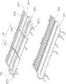
图3是图2所示电连接器部分结构另一角度的立体分解图。FIG. 3 is an exploded perspective view from another angle of the partial structure of the electrical connector shown in FIG. 2 .
图4是图1所示电连接器导电外壳的立体图。FIG. 4 is a perspective view of the conductive shell of the electrical connector shown in FIG. 1 .
图5是图1所示电连接器沿A-A线的剖视图。FIG. 5 is a cross-sectional view of the electrical connector shown in FIG. 1 along line A-A.
图6是图1所示电连接器沿B-B线的剖视图。FIG. 6 is a cross-sectional view of the electrical connector shown in FIG. 1 along line B-B.
图7是图1所示电连接器沿C-C线的剖视图。FIG. 7 is a cross-sectional view of the electrical connector shown in FIG. 1 along line C-C.
【具体实施方式】【Detailed ways】
请参阅图1及图2,本实用新型提供了一种电连接器100,该电连接器100包括导电外壳1、收容于导电外壳1内的端子模组2及屏蔽件3,所述导电外壳1设有向前延伸的对接部11及自导电外壳1后端面凹设的容置腔12,所述对接部11呈对称设置且具有相对设置的第一对接面111及第二对接面,端子模组2固定于容置腔12内,所述屏蔽件3设置于容置腔12内并与导电外壳1相接触。所述导电外壳1采用粉末冶金技术制成,所述屏蔽件3的设置在端子模组2与屏蔽件3先后组装入导电外壳1内后注射入塑胶材料4时起到压紧端子模组2的作用。Please refer to Figure 1 and Figure 2, the utility model provides an
请参阅图2及图3,所述端子模组2包括第一绝缘体21及固持于第一绝缘体的第一端子23,即形成第一端子模组2a,第一绝缘体21具有相对设置的第一面211及第二面212,第一端子23具有凸伸出第一绝缘体21的第一面211的第一接触部231,上述屏蔽件3抵压于第一绝缘体21的第二面212以使第一端子23的第一接触部231裸露于上述第一对接面111。所述端子模组2还包括第二绝缘体22及固持于第二绝缘体22的第二端子24,即形成第二端子模组2b,第二端子模组的结构与第一端子模组大致相同,第二绝缘体22具有相对设置的第三面221及第四面222,第二端子24具有凸伸出第二绝缘体22的第三面221的第二接触部241,所述屏蔽件3位于第一端子23与第二端子24之间且进一步抵压于第二绝缘体22的第四面222以使第二端子24的第二接触部241裸露于上述第二对接面112。两个端子模组的第二、四面均为面向内侧或者说彼此相同的面,第一、第三面均为面向外侧或者说彼此相同的面。Please refer to FIG. 2 and FIG. 3, the
下面对与屏蔽件3相接触抵压的第一、第二绝缘体21、22的第二、第四面212、222进行详细的描述,相同结构则采用相同的标号。所述第二、第四面均设有邻近后端的第一凹陷部223及紧邻第一、第二接触部的第二凹陷部224,第二、第四面212、222的第一、第二凹陷部223、224沿纵长方向延伸且第二凹陷部224分别贯穿第二、第四面212、222的侧面,第一凹陷部223则贯穿端子模组的后侧,结合图5,在端子模组插入后,因为第一凹陷部223的存在,屏蔽件3与两个端子模组的绝缘体之间存在一定间隙,在后续注射入塑胶材料4时,模具在压紧两端子模组时起到缓冲让位的作用。The second and
第二、第四面212、222的除凹陷部外的其他部分则成为支撑面225,第二、第四面212、222在间隔第一、第二接触部处延伸有肋条227,该等肋条227分别间隔于第一、第二端子23、24而排列。结合图7,前述部分肋条227较长,可以抵接于导电外壳1的内表面的前端,有助于缓冲塑料材料4注入时的冲击力。Other parts of the second and
在本实施方式中,所述屏蔽件3设有位于第一端子23与第二端子24之间的屏蔽部31,屏蔽部31的前端被打薄,该屏蔽件3于屏蔽部31的前端两侧向外延伸有弹性臂32,该弹性臂32与导电外壳1相接触,屏蔽部31与弹性臂32之间形成让位槽33,用以在屏蔽件3组装入容置腔内时用于让位,所述弹性臂32向前进一步延伸形成钩状的凸伸部321,结合图5及图7,该凸伸部321的前端向内弯折且位于第一、第二绝缘体21、22之间。In this embodiment, the
进一步的,所述屏蔽件3的两个相对表面分别设有向前延伸的第一限位部311,所述第一、第二绝缘体21、22于第二、第四面212、222分别设有可对应于第一限位部311的第二限位部26,两个表面的第一限位部311呈中心对称,且分别与第二限位部配合。在本实施方式中,所述第一限位部311包括并列设置于凹陷于表面的第一插槽3111及凸出表面的第一插肋3112,所述第一插槽3111凹设入表面且向前延伸并贯穿两表面的前端边缘,所述第一插肋3112凸设于两个表面且向前延伸至两个表面前端的边缘。所述第二限位部26包括与第一限位部311的第一插槽3111与第一插肋3112对应设置的第二插肋262与第二插槽261。当然,在其他实施方式中,第一限位部311及第二限位部26也可以有其他的设置方式。屏蔽件3与第一、第二端子模组的这种配合关系,能够较好的定位端子模组于容置腔内,避免注塑过程中的偏移,同时,参图7,弹性臂32倾斜设置,且有让位槽33,能够较好地保证屏蔽件沿着导电壳体的内侧移动,且保证零号的接触;让位槽等槽道的存在,后续注塑的塑胶材料可以部分进去,更好的固定端子模组结构。Further, the two opposite surfaces of the
请参阅图4及图6,所述导电外壳1具有面向容置腔12的内表面,导电外壳1自该内表面水平延伸有位于容置腔12的导引柱14,所述第一、第二绝缘体21、22均设有与之相对应的导引块25,导引柱14位于第一、第二绝缘体21、22对应的导引块25之间使得两个端子模组2组装入容置腔12后分别位于导引柱14的上下两侧,结合图7,组装入容置腔12的屏蔽件3则位于两个导引柱14之间。Referring to Fig. 4 and Fig. 6, the
完成上述组装后,将对此电连接器注射入塑胶材料4以填充相应的空间,所述对接部11的第一、第二对接面分别凹设有与容置腔12连通的缺口部13,端子模组2抵持于对接部11的内表面,第一、第二端子23、24的接触部231、241分别凸出于上述两个缺口部13,且所述缺口部13填充有塑胶材料4,结合图5,塑胶材料4密封端子模组使得塑胶材料4与对接部11的第一、第二对接面111、112相平齐。After the above-mentioned assembly is completed, the electrical connector is injected into the
综上,屏蔽件3设置于容置腔12内并与导电外壳1相接触,同时可抵压端子模组2,屏蔽件3的设置兼具抵压端子模组及屏蔽两排端子间的信号干扰的作用。To sum up, the
本实施方式为本实用新型较佳实施方式,当然,本实用新型也可采用其他实施方式,此处不再一一赘述。This implementation mode is a preferred implementation mode of the utility model, of course, the utility model can also adopt other implementation modes, which will not be repeated here.
Claims (10)
Translated fromChinesePriority Applications (3)
| Application Number | Priority Date | Filing Date | Title |
|---|---|---|---|
| CN201320682317.9UCN203631874U (en) | 2013-11-01 | 2013-11-01 | Electric connector |
| US14/531,978US9257801B2 (en) | 2013-11-01 | 2014-11-03 | Electrical connector with shielding plate |
| US14/855,315US9413119B2 (en) | 2013-11-01 | 2015-09-15 | Electrical connector with an improved mating plate |
Applications Claiming Priority (1)
| Application Number | Priority Date | Filing Date | Title |
|---|---|---|---|
| CN201320682317.9UCN203631874U (en) | 2013-11-01 | 2013-11-01 | Electric connector |
Publications (1)
| Publication Number | Publication Date |
|---|---|
| CN203631874Utrue CN203631874U (en) | 2014-06-04 |
Family
ID=50818318
Family Applications (1)
| Application Number | Title | Priority Date | Filing Date |
|---|---|---|---|
| CN201320682317.9UExpired - Fee RelatedCN203631874U (en) | 2013-11-01 | 2013-11-01 | Electric connector |
Country Status (2)
| Country | Link |
|---|---|
| US (1) | US9257801B2 (en) |
| CN (1) | CN203631874U (en) |
Cited By (3)
| Publication number | Priority date | Publication date | Assignee | Title |
|---|---|---|---|---|
| CN104577460A (en)* | 2015-01-28 | 2015-04-29 | 丰岛电子科技(苏州)有限公司 | Electric connector |
| CN105261892A (en)* | 2015-11-10 | 2016-01-20 | 丰岛电子科技(苏州)有限公司 | Electric connector |
| CN107681371A (en)* | 2016-08-01 | 2018-02-09 | 富士康(昆山)电脑接插件有限公司 | Electric connector |
Families Citing this family (27)
| Publication number | Priority date | Publication date | Assignee | Title |
|---|---|---|---|---|
| US10720734B2 (en)* | 2013-07-19 | 2020-07-21 | Foxconn Interconnect Technology Limited | Flippable electrical connector |
| US9520683B2 (en)* | 2014-08-14 | 2016-12-13 | Foxconn Interconnect Technology Limited | Connector and manufacturing method thereof |
| CN204289826U (en)* | 2015-01-06 | 2015-04-22 | 上海莫仕连接器有限公司 | Electric connector |
| CN105449443B (en)* | 2015-02-11 | 2018-03-06 | 富士康(昆山)电脑接插件有限公司 | Electric connector and its manufacture method |
| CN108701922B (en) | 2015-07-07 | 2020-02-14 | Afci亚洲私人有限公司 | Electrical connector |
| CN204947246U (en)* | 2015-07-29 | 2016-01-06 | 富士康(昆山)电脑接插件有限公司 | Electric connector |
| US9728898B1 (en) | 2016-02-01 | 2017-08-08 | Microsoft Technology Licensing, Llc | Conductive shell for a cable assembly |
| TWD186994S (en)* | 2016-06-02 | 2017-12-01 | 鴻騰精密科技股份有限公司 | Part of electrical connector |
| CN114512840B (en) | 2017-10-30 | 2024-06-25 | 安费诺富加宜(亚洲)私人有限公司 | Low crosstalk card edge connector |
| US10601181B2 (en) | 2017-12-01 | 2020-03-24 | Amphenol East Asia Ltd. | Compact electrical connector |
| CN109888550A (en)* | 2017-12-06 | 2019-06-14 | 富士康(昆山)电脑接插件有限公司 | Electric connector and its component |
| CN108232691B (en)* | 2018-01-29 | 2023-12-01 | 欧品电子(昆山)有限公司 | Double-shielding high-speed butt-joint connector |
| CN113169484A (en) | 2018-10-09 | 2021-07-23 | 安费诺商用电子产品(成都)有限公司 | High density edge connector |
| TWM576774U (en) | 2018-11-15 | 2019-04-11 | 香港商安費諾(東亞)有限公司 | Metal case with anti-displacement structure and connector thereof |
| US11381015B2 (en) | 2018-12-21 | 2022-07-05 | Amphenol East Asia Ltd. | Robust, miniaturized card edge connector |
| CN109546469B (en)* | 2019-01-09 | 2023-11-03 | 四川华丰科技股份有限公司 | Female end signal transmission module with metal shielding plate |
| CN109546472B (en)* | 2019-01-09 | 2023-11-03 | 四川华丰科技股份有限公司 | Female end signal transmission module with metal shielding plate |
| CN109546470B (en)* | 2019-01-09 | 2023-10-10 | 四川华丰科技股份有限公司 | Female end signal transmission module with metal shielding plate |
| CN109546462B (en)* | 2019-01-09 | 2023-11-03 | 四川华丰科技股份有限公司 | Female end signal transmission module with metal shielding plate |
| CN109546461B (en)* | 2019-01-09 | 2023-11-03 | 四川华丰科技股份有限公司 | Female end signal transmission module with metal shielding plate |
| TWM582251U (en) | 2019-04-22 | 2019-08-11 | 香港商安費諾(東亞)有限公司 | Connector set with hidden locking mechanism and socket connector thereof |
| US11799230B2 (en) | 2019-11-06 | 2023-10-24 | Amphenol East Asia Ltd. | High-frequency electrical connector with in interlocking segments |
| US11588277B2 (en) | 2019-11-06 | 2023-02-21 | Amphenol East Asia Ltd. | High-frequency electrical connector with lossy member |
| US11652307B2 (en) | 2020-08-20 | 2023-05-16 | Amphenol East Asia Electronic Technology (Shenzhen) Co., Ltd. | High speed connector |
| CN212874843U (en) | 2020-08-31 | 2021-04-02 | 安费诺商用电子产品(成都)有限公司 | Electrical connector |
| US12176650B2 (en) | 2021-05-05 | 2024-12-24 | Amphenol East Asia Limited (Hong Kong) | Electrical connector with guiding structure and mating groove and method of connecting electrical connector |
| CN215266741U (en) | 2021-08-13 | 2021-12-21 | 安费诺商用电子产品(成都)有限公司 | High-performance card connector meeting high-bandwidth transmission |
Family Cites Families (7)
| Publication number | Priority date | Publication date | Assignee | Title |
|---|---|---|---|---|
| CN201142421Y (en)* | 2007-12-29 | 2008-10-29 | 富士康(昆山)电脑接插件有限公司 | electrical connector |
| US7758380B2 (en)* | 2008-05-16 | 2010-07-20 | Hon Hai Precision Ind. Co., Ltd. | Stacked electrical connector with improved shell for EMI protection |
| TW201019548A (en)* | 2008-11-03 | 2010-05-16 | Chant Sincere Co Ltd | Universal serial bus and its manufacturing method |
| TWM387405U (en) | 2010-04-02 | 2010-08-21 | Main Super Entpr Co Ltd | Improved structure of connector |
| TWM387416U (en)* | 2010-04-29 | 2010-08-21 | Advanced Connectek Inc | High-frequency socket connector |
| US9022802B2 (en)* | 2013-03-18 | 2015-05-05 | Concraft Holding Co., Ltd. | Terminal module |
| US9124008B2 (en)* | 2013-08-29 | 2015-09-01 | Tyco Electronics Corporation | Electrical connector |
- 2013
- 2013-11-01CNCN201320682317.9Upatent/CN203631874U/ennot_activeExpired - Fee Related
- 2014
- 2014-11-03USUS14/531,978patent/US9257801B2/enactiveActive
Cited By (4)
| Publication number | Priority date | Publication date | Assignee | Title |
|---|---|---|---|---|
| CN104577460A (en)* | 2015-01-28 | 2015-04-29 | 丰岛电子科技(苏州)有限公司 | Electric connector |
| CN105261892A (en)* | 2015-11-10 | 2016-01-20 | 丰岛电子科技(苏州)有限公司 | Electric connector |
| CN107681371A (en)* | 2016-08-01 | 2018-02-09 | 富士康(昆山)电脑接插件有限公司 | Electric connector |
| CN107681371B (en)* | 2016-08-01 | 2020-06-02 | 富士康(昆山)电脑接插件有限公司 | Electrical connector |
Also Published As
| Publication number | Publication date |
|---|---|
| US9257801B2 (en) | 2016-02-09 |
| US20150126068A1 (en) | 2015-05-07 |
Similar Documents
| Publication | Publication Date | Title |
|---|---|---|
| CN203631874U (en) | Electric connector | |
| CN104425995B (en) | Electrical connector and assembly thereof | |
| CN204947245U (en) | Electric connector | |
| CN204361372U (en) | Electric connector | |
| CN201430237Y (en) | Electric connector | |
| CN202997168U (en) | Electric connector | |
| TWM534916U (en) | Electrical connector | |
| CN204315776U (en) | electrical connector | |
| CN205159614U (en) | socket connector | |
| CN203747078U (en) | electrical connector | |
| CN104112968A (en) | Socket electric connector and manufacture method thereof | |
| CN203326171U (en) | Electric connector | |
| CN107732529A (en) | Electric connector and its manufacture method | |
| CN207250794U (en) | Electric connector | |
| CN104283035B (en) | Electric connector combination and its assemble method | |
| TW201618390A (en) | Connector and making method of the same | |
| TWM484213U (en) | Electrical connector | |
| CN202363652U (en) | electrical connector | |
| CN103972700A (en) | Electrical connector | |
| CN202363653U (en) | Electric connector with improved structure | |
| CN218632582U (en) | USB Type C connector | |
| CN201160138Y (en) | Electrical Connector Assembly | |
| CN205828790U (en) | USB Type‑C receptacle connector with enhanced mating force | |
| CN201430235Y (en) | Electric connector | |
| TWI573342B (en) | Connector and a manufacturing method thereof |
Legal Events
| Date | Code | Title | Description |
|---|---|---|---|
| C14 | Grant of patent or utility model | ||
| GR01 | Patent grant | ||
| ASS | Succession or assignment of patent right | Free format text:FORMER OWNER: HONGFUJIN PRECISE INDUSTRY CO., LTD. Effective date:20141202 | |
| C41 | Transfer of patent application or patent right or utility model | ||
| TR01 | Transfer of patent right | Effective date of registration:20141202 Address after:215316 Kunshan Development Zone, Jiangsu hi tech Industrial Park, North Road, No. 999 Patentee after:Foxconn Kunshan Computer Connector Co.,Ltd. Address before:Suzhou City, Jiangsu province 215316 Kunshan city Yushan Town Road No. 999 Patentee before:Foxconn Kunshan Computer Connector Co.,Ltd. Patentee before:HON HAI PRECISION INDUSTRY Co.,Ltd. | |
| CF01 | Termination of patent right due to non-payment of annual fee | Granted publication date:20140604 | |
| CF01 | Termination of patent right due to non-payment of annual fee |