CN203604216U - Bulb type diving tubular pump device - Google Patents
Bulb type diving tubular pump deviceDownload PDFInfo
- Publication number
- CN203604216U CN203604216UCN201320667582.XUCN201320667582UCN203604216UCN 203604216 UCN203604216 UCN 203604216UCN 201320667582 UCN201320667582 UCN 201320667582UCN 203604216 UCN203604216 UCN 203604216U
- Authority
- CN
- China
- Prior art keywords
- bulb
- guide vane
- pump device
- impeller
- bulb body
- Prior art date
- Legal status (The legal status is an assumption and is not a legal conclusion. Google has not performed a legal analysis and makes no representation as to the accuracy of the status listed.)
- Expired - Fee Related
Links
- 230000009189divingEffects0.000titleabstract4
- XLYOFNOQVPJJNP-UHFFFAOYSA-NwaterSubstancesOXLYOFNOQVPJJNP-UHFFFAOYSA-N0.000claimsabstractdescription58
- 230000007704transitionEffects0.000claimsabstractdescription14
- 238000009792diffusion processMethods0.000claimsabstractdescription9
- 239000002184metalSubstances0.000claimsdescription15
- 239000011150reinforced concreteSubstances0.000claimsdescription7
- 230000008602contractionEffects0.000claimsdescription2
- 238000010276constructionMethods0.000abstractdescription7
- 238000013461designMethods0.000abstractdescription7
- 238000009826distributionMethods0.000abstractdescription2
- 238000009434installationMethods0.000description6
- 230000000694effectsEffects0.000description3
- 238000012423maintenanceMethods0.000description3
- 238000005086pumpingMethods0.000description3
- 238000011084recoveryMethods0.000description3
- 238000009412basement excavationMethods0.000description2
- 238000010586diagramMethods0.000description2
- 238000004519manufacturing processMethods0.000description2
- 238000000465mouldingMethods0.000description2
- 238000012545processingMethods0.000description2
- 229910000831SteelInorganic materials0.000description1
- 230000002411adverseEffects0.000description1
- 230000005540biological transmissionEffects0.000description1
- 238000001816coolingMethods0.000description1
- 239000000498cooling waterSubstances0.000description1
- 230000007812deficiencyEffects0.000description1
- 238000009415formworkMethods0.000description1
- 230000010354integrationEffects0.000description1
- 238000005461lubricationMethods0.000description1
- 238000000034methodMethods0.000description1
- 238000011160researchMethods0.000description1
- 239000010959steelSubstances0.000description1
Images


Classifications
- Y—GENERAL TAGGING OF NEW TECHNOLOGICAL DEVELOPMENTS; GENERAL TAGGING OF CROSS-SECTIONAL TECHNOLOGIES SPANNING OVER SEVERAL SECTIONS OF THE IPC; TECHNICAL SUBJECTS COVERED BY FORMER USPC CROSS-REFERENCE ART COLLECTIONS [XRACs] AND DIGESTS
- Y02—TECHNOLOGIES OR APPLICATIONS FOR MITIGATION OR ADAPTATION AGAINST CLIMATE CHANGE
- Y02A—TECHNOLOGIES FOR ADAPTATION TO CLIMATE CHANGE
- Y02A20/00—Water conservation; Efficient water supply; Efficient water use
- Y02A20/20—Controlling water pollution; Waste water treatment
Landscapes
- Structures Of Non-Positive Displacement Pumps (AREA)
Abstract
Description
Translated fromChinese技术领域technical field
本实用新型涉及一种泵装置的结构型式,尤其涉及贯流泵装置的结构,属于水利水电工程技术领域。The utility model relates to a structure type of a pump device, in particular to a structure of a through-flow pump device, and belongs to the technical field of water conservancy and hydropower engineering.
背景技术Background technique
潜水贯流泵装置将电机、轴承及齿轮箱等设备布置在流道内,机组段采用全金属壳体。泵装置进、出水流道顺直,水力损失小,泵装置水力效率高;土建结构简单,开挖深度小;潜水电机与泵连成一体,结构紧凑;不需要润滑、冷却用水,不需要附加的散热设施等优点。The submersible tubular pump device arranges the motor, bearing, gear box and other equipment in the flow channel, and the unit section adopts an all-metal shell. The water inlet and outlet channels of the pump device are straight, the hydraulic loss is small, and the hydraulic efficiency of the pump device is high; the civil structure is simple, and the excavation depth is small; the submersible motor and the pump are integrated into one body, and the structure is compact; no lubrication, cooling water, and no additional The cooling facilities and other advantages.
叶轮、导叶体与进、出水流道相互耦合的水力性能共同决定了泵装置整体水力效率的高低,在相同水力模型情况下,出水流道的水力损失与叶轮出口环量的回收效果是影响泵装置整体水力性能的主要因素。潜水贯流泵装置在导叶体出口处安装有灯泡体,若灯泡体设计不好将会直接增加灯泡体段的水力损失,进而导致出水流道的水力损失增加,甚至会导致灯泡体段内产生漩涡等不良流态,从而大幅度降低贯流泵装置的水力效率,严重时将会影响泵装置的安全稳定运行。灯泡体的水力损失占整个过流部件水力损失的比重相对较大,无论是灯泡体的水力损失还是对导叶体出口剩余环量的进一步回收都与灯泡体的设计直接相关。在灯泡式潜水贯流泵装置进、出水流道三维形体方面也开展了一部分研究工作,泵装置的水力效率获得了提高,但传统的潜水贯流泵装置采用水平式进、出水流道,但这种型式的进、出水流道出口顶高程较低,导致出水池翼墙的高度较大,增加了工程的土建投资;泵装置在低扬程运行时,存在传统的导叶体对叶轮出口环量的回收效果并不显著的问题。The hydraulic performance of the impeller, the guide vane body, and the inlet and outlet channels jointly determine the overall hydraulic efficiency of the pump device. Under the same hydraulic model, the hydraulic loss of the outlet channel and the recovery effect of the impeller outlet circulation are the most important factors. A major factor in the overall hydraulic performance of the pump unit. The submersible tubular pump device is equipped with a bulb body at the outlet of the guide vane body. If the bulb body design is not good, it will directly increase the hydraulic loss of the bulb body section, which will lead to an increase in the hydraulic loss of the outlet flow channel, and even cause the bulb body section to Whirlpool and other adverse flow patterns will be generated, which will greatly reduce the hydraulic efficiency of the tubular pump device, and in severe cases will affect the safe and stable operation of the pump device. The hydraulic loss of the bulb body accounts for a relatively large proportion of the hydraulic loss of the entire flow-passing part. Whether it is the hydraulic loss of the bulb body or the further recovery of the remaining circulation at the outlet of the guide vane body, it is directly related to the design of the bulb body. Some research work has also been carried out on the three-dimensional shape of the inlet and outlet channels of the bulb-type submersible tubular pump device, and the hydraulic efficiency of the pump device has been improved. However, the traditional submersible tubular pump device uses horizontal inlet and outlet channels. This type of inlet and outlet flow channel has a lower outlet top elevation, which leads to a higher height of the wing wall of the outlet pool, which increases the civil construction investment of the project; The amount of recovery effect is not significant.
实用新型内容Utility model content
本实用新型的目的就是针对上述现有技术存在的不足,提供一种高效的新型灯泡式潜水贯流泵装置,改善因导叶体和灯泡体设计不当引起的泵装置水力效率低的问题,优化进、出水流道的三维形体,进一步提高潜水贯流泵装置的水力性能。The purpose of this utility model is to provide a new high-efficiency bulb-type submersible tubular pump device for the above-mentioned deficiencies in the prior art, to improve the problem of low hydraulic efficiency of the pump device caused by improper design of the guide vane body and the bulb body, and to optimize The three-dimensional shape of the inlet and outlet channels further improves the hydraulic performance of the submersible tubular pump device.
本实用新型的目的是这样实现的,灯泡式潜水贯流泵装置,包括依次设置连接的进水流道、叶轮、导叶体、灯泡体、出水流道,其特征是,所述进水流道为渐缩形体,由矩形进口断面先经单边收缩光滑过渡至过渡圆形断面,过渡圆形断面再经对称渐缩光滑过渡至叶轮进口圆形断面,进水流道为钢筋混凝土结构或金属结构;所述导叶体为扩散导叶体,导叶体为金属结构体,导叶体轮毂与叶轮轮毂、灯泡体的衔接部分过渡平顺;所述灯泡体的外形呈水滴形,灯泡体尾部为尖锥形,灯泡体设有支撑件,灯泡体支承在支撑件上;所述出水流道为单边渐扩形体,出水流道立面上、下缘型线为上翘式光滑圆弧线,出水流道由灯泡体出口圆形断面经单边渐扩光滑过渡至矩形出口断面,出水流道为钢筋混凝土结构或金属结构。The purpose of this utility model is achieved in this way, the light bulb type submersible tubular pump device, including the water inlet channel, the impeller, the guide vane body, the bulb body and the water outlet channel that are connected in sequence, it is characterized in that the water inlet channel is Tapered shape, from the rectangular inlet section to a transitional circular section through unilateral contraction, and then to a circular section at the impeller inlet through a symmetrical taper. The water inlet channel is a reinforced concrete structure or a metal structure; The guide vane body is a diffusion guide vane body, the guide vane body is a metal structure, and the transition between the hub of the guide vane body, the hub of the impeller and the bulb body is smooth; the shape of the bulb body is drop-shaped, and the tail of the bulb body is pointed Conical, the bulb body is provided with a support, and the bulb body is supported on the support; the water outlet channel is a unilateral gradually expanding body, and the vertical surface and lower edge of the water outlet channel are curved smooth arc lines. The water outlet channel is smoothly transitioned from the circular section of the bulb body outlet to the rectangular outlet section through unilateral gradual expansion, and the water outlet channel is a reinforced concrete structure or a metal structure.
所述过渡圆形断面直径为1.33倍的叶轮名义直径。The diameter of the transition circular section is 1.33 times the nominal diameter of the impeller.
所述扩散导叶体的导叶体单边扩散角为3° ~ 8°。The unilateral diffusion angle of the guide vane body of the diffusion guide vane body is 3° to 8°.
所述灯泡体长度为叶轮名义直径的2.40 ~ 3.50倍,灯泡体最大宽度为叶轮名义直径的0.73倍。The length of the bulb body is 2.40 to 3.50 times the nominal diameter of the impeller, and the maximum width of the bulb body is 0.73 times the nominal diameter of the impeller.
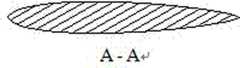
所述支撑件为水滴形断面的支撑柱或矩形断面的支撑筋板。The support member is a support column with a drop-shaped section or a support rib with a rectangular section.
所述灯泡体由金属加工制成。The bulb body is made of metal processing.
本实用新型以流速分布均匀和水力损失小为原则对进水流道、灯泡体及出水流道进行了优化设计,以达到进水流道、灯泡体、出水流道的水力损失进一步减小,提高泵装置水力效率的目的。针对传统导叶体在泵装置低扬程运行时回收叶轮出口环量效果不显著的问题,导叶体采用扩散导叶体,导叶体轮毂与叶轮轮毂、灯泡体的衔接部分过渡平顺,无凸起;进水流道采用渐缩形体, 灯泡体整体外形采用水滴形,灯泡体的支撑件共计5片,支撑件可采用水滴形断面的支撑柱或矩形断面的支撑筋板;灯泡体为金属加工制作安装;出水流道采用单边渐扩形体,出水流道立面上、下缘型线为上翘式光滑圆弧线,出水流道由灯泡体出口圆形断面经单边渐扩光滑过渡至出水流道的矩形出口断面,其为钢筋混凝土结构或金属结构。The utility model optimizes the design of the water inlet flow channel, the bulb body and the water outlet flow channel based on the principle of uniform flow velocity distribution and small hydraulic loss, so as to further reduce the hydraulic loss of the water inlet flow channel, bulb body, and water outlet flow channel, and improve the efficiency of the pump. The purpose of the hydraulic efficiency of the installation. Aiming at the problem that the traditional guide vane body has no significant effect of recovering the impeller outlet circulation when the pump device is running at low lift, the guide vane body adopts a diffuse guide vane body, and the transition between the guide vane body hub, the impeller hub, and the bulb body is smooth, and there is no convexity. The water inlet channel adopts a tapered shape, and the overall shape of the bulb body adopts a drop shape. There are 5 supports for the bulb body in total. Manufacture and installation; the water outlet flow channel adopts a unilateral gradually expanding shape, and the upper and lower edge molding lines of the water outlet flow channel are upturned smooth arc lines, and the water outlet flow channel transitions smoothly from the circular section of the bulb body outlet through the unilateral gradual expansion Rectangular outlet section to the outlet channel, which is of reinforced concrete structure or metal structure.
潜水电机与叶轮同轴连接的机电一体化产品,和传动设备均位于出水流道内部,叶轮室采用对开式结构,无需在拆卸水泵时移动电机即可将叶轮室整体吊起,方便水泵的安装检修,减少了泵站机电等设备维修的空间,降低了土建投资。The electromechanical integration product in which the submersible motor and the impeller are coaxially connected, and the transmission equipment is located inside the water outlet channel. The impeller chamber adopts a split structure, and the impeller chamber can be lifted as a whole without moving the motor when disassembling the water pump, which is convenient for the pump. Installation and maintenance reduces the space for maintenance of electromechanical and other equipment in the pumping station, and reduces the investment in civil engineering.
进、出水流道中心线与叶轮、导叶中心线共线,底板顶部高程与叶轮室相近,泵房开挖深度仅限叶轮的淹没深度影响,无需考虑水泵轴、电机轴的长度,方便设计安装,更节省了土建投资。The center line of the inlet and outlet channels is collinear with the center line of the impeller and guide vane, and the elevation of the top of the bottom plate is similar to that of the impeller chamber. The excavation depth of the pump room is only affected by the submersion depth of the impeller, without considering the length of the pump shaft and motor shaft, which is convenient for design Installation saves civil investment.
本实用新型适用于区域抗旱、城市防洪排涝和城镇供水等领域,相比同类其他泵装置,其具有安全可靠,工程造价低,安装维护方便,运行费用少,更加高效和安全。The utility model is suitable for areas such as regional drought resistance, urban flood control and drainage, and urban water supply. Compared with other similar pump devices, the utility model has the advantages of safety, reliability, low engineering cost, convenient installation and maintenance, low operating cost, and is more efficient and safer.
附图说明Description of drawings
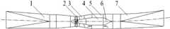
图1为本实用新型的平面结构示意图。Fig. 1 is a schematic diagram of the planar structure of the utility model.
图2为本实用新型的立面结构示意图。Fig. 2 is a schematic diagram of the facade structure of the utility model.
图3为本实用新型的灯泡体部位的局部放大示意图。Fig. 3 is a partially enlarged schematic view of the bulb body of the present invention.
图4为本实用新型的支撑件剖面图(图3中A-A剖面图)。Fig. 4 is a sectional view of the support of the present invention (A-A sectional view in Fig. 3).
图中:1进水流道、2叶轮、3导叶体、4灯泡体、5支撑件、6灯泡体尾部、7出水流道。In the figure: 1 water inlet channel, 2 impeller, 3 guide vane body, 4 bulb body, 5 support member, 6 bulb body tail, 7 water outlet channel.
具体实施方式Detailed ways
灯泡式潜水贯流泵装置由进水流道1、叶轮2、导叶体3、灯泡体4、出水流道7组成,进水流道1为渐缩形体,由矩形进口断面先经单边收缩光滑过渡至过渡圆形断面,过渡圆形断面再经对称渐缩光滑过渡至叶轮进口圆形断面,进水流道为钢筋混凝土结构或金属结构。进水流道1出口断面与泵叶轮2的进口断面平顺连接。所述导叶体为扩散导叶体,导叶体为金属结构体。叶轮2的出口与扩散导叶体3的进口光滑过渡连接,导叶体3的进口与灯泡体4的进口平顺连接。灯泡体的外形呈水滴形,灯泡体尾部为尖锥形,灯泡体设有支撑件,灯泡体支承在支撑件上。出水流道为单边渐扩形体,出水流道立面上、下缘型线为上翘式光滑圆弧线,出水流道由灯泡体出口圆形断面经单边渐扩光滑过渡至矩形出口断面,出水流道为钢筋混凝土结构或金属结构。灯泡体4的出口与出水流道7的进口平顺连接,动力装置采用潜水电机,进水流道1、叶轮2、导叶体3、灯泡体4及出水流道7均位于同一平面内,泵装置整体高度小,土建投资省。The bulb-type submersible tubular pump device is composed of
本实用新型的实施需按照设计图纸要求施工,对于大型泵站的进水流道1、出水流道7由施工单位负责在工程现场放样施工。施工时需要按照图纸要求采用定型木质或钢模板,进水流道1和出水流道7均为渐变形体,要求各断面间为平滑过渡,立模后在现场浇注成型。灯泡体4(含灯泡体尾部6)可在金属加工厂内采用加工制作以保证曲面的制作精度,同时可叶轮2、导叶体3及灯泡体4先安装再进行整体吊装。The implementation of the utility model needs to be constructed according to the requirements of the design drawings, and the construction unit is responsible for setting out the construction on the project site for the water
对于中小型泵站,灯泡式潜水贯流泵装置的进水流道1、出水流道7均可采用金属制造,运至施工现场进行拼接安装。For small and medium-sized pumping stations, both the
Claims (6)
Translated fromChinesePriority Applications (1)
| Application Number | Priority Date | Filing Date | Title |
|---|---|---|---|
| CN201320667582.XUCN203604216U (en) | 2013-10-28 | 2013-10-28 | Bulb type diving tubular pump device |
Applications Claiming Priority (1)
| Application Number | Priority Date | Filing Date | Title |
|---|---|---|---|
| CN201320667582.XUCN203604216U (en) | 2013-10-28 | 2013-10-28 | Bulb type diving tubular pump device |
Publications (1)
| Publication Number | Publication Date |
|---|---|
| CN203604216Utrue CN203604216U (en) | 2014-05-21 |
Family
ID=50716893
Family Applications (1)
| Application Number | Title | Priority Date | Filing Date |
|---|---|---|---|
| CN201320667582.XUExpired - Fee RelatedCN203604216U (en) | 2013-10-28 | 2013-10-28 | Bulb type diving tubular pump device |
Country Status (1)
| Country | Link |
|---|---|
| CN (1) | CN203604216U (en) |
Cited By (6)
| Publication number | Priority date | Publication date | Assignee | Title |
|---|---|---|---|---|
| CN105507370A (en)* | 2015-11-30 | 2016-04-20 | 浙江省第一水电建设集团股份有限公司 | Shaft well tubular pump flow channel concrete special-shaped steel mould one-stage molding construction method |
| JP2018003838A (en)* | 2016-06-29 | 2018-01-11 | 廣達電腦股▲ふん▼有限公司 | A system that provides streamlined airflow |
| CN109707661A (en)* | 2019-01-08 | 2019-05-03 | 扬州大学 | A pump device with a special-shaped water guide cone |
| CN114396393A (en)* | 2021-11-08 | 2022-04-26 | 江苏大学 | An adaptive design method for guide vanes of a bulb tubular pump and guide vanes of a bulb tubular pump |
| CN116104766A (en)* | 2023-02-27 | 2023-05-12 | 扬州大学 | Symmetrical airfoil support body structure in bulb tubular pump device and method for improving water flow state thereof |
| CN116255337A (en)* | 2023-03-08 | 2023-06-13 | 扬州大学 | A New Bulb Tubular Flow Pump with Combined Groove Drag Reduction |
- 2013
- 2013-10-28CNCN201320667582.XUpatent/CN203604216U/ennot_activeExpired - Fee Related
Cited By (7)
| Publication number | Priority date | Publication date | Assignee | Title |
|---|---|---|---|---|
| CN105507370A (en)* | 2015-11-30 | 2016-04-20 | 浙江省第一水电建设集团股份有限公司 | Shaft well tubular pump flow channel concrete special-shaped steel mould one-stage molding construction method |
| JP2018003838A (en)* | 2016-06-29 | 2018-01-11 | 廣達電腦股▲ふん▼有限公司 | A system that provides streamlined airflow |
| US10989221B2 (en) | 2016-06-29 | 2021-04-27 | Quanta Computer Inc. | Cooling system for streamlined airflow |
| CN109707661A (en)* | 2019-01-08 | 2019-05-03 | 扬州大学 | A pump device with a special-shaped water guide cone |
| CN114396393A (en)* | 2021-11-08 | 2022-04-26 | 江苏大学 | An adaptive design method for guide vanes of a bulb tubular pump and guide vanes of a bulb tubular pump |
| CN116104766A (en)* | 2023-02-27 | 2023-05-12 | 扬州大学 | Symmetrical airfoil support body structure in bulb tubular pump device and method for improving water flow state thereof |
| CN116255337A (en)* | 2023-03-08 | 2023-06-13 | 扬州大学 | A New Bulb Tubular Flow Pump with Combined Groove Drag Reduction |
Similar Documents
| Publication | Publication Date | Title |
|---|---|---|
| CN203604216U (en) | Bulb type diving tubular pump device | |
| CN203067358U (en) | Novel open-type water pump water inlet pool | |
| CN203067354U (en) | Novel sidewise S-shaped shaft extension tubular pump device | |
| CN104532907B (en) | pump station structure | |
| CN102182706B (en) | S-shaped downwards horizontal axis-extending tubular pump device | |
| WO2015184999A1 (en) | Gravity forced high-efficiency vertical liquid pumping device with large volume | |
| CN101892654B (en) | Conical swirling flow vertical shaft | |
| CN202500823U (en) | Composite type flare tube | |
| CN206174043U (en) | Middle -size and small -size box culvert formula water intake structure for pump station | |
| CN102269181A (en) | Butt matching low-hump-type bidirectional water-outlet flow channel | |
| CN107956950A (en) | A kind of outlet passage with flow Self-balancing | |
| CN103603763A (en) | Bulb tubular turbine for micro-head power generation of water plant | |
| CN103790838B (en) | The two-way humble lift water plug of Ω shape | |
| CN206667364U (en) | A kind of novel submerged pumping plant | |
| CN204942089U (en) | A kind of through-flow pump diffusion diffuser | |
| CN202531390U (en) | Gas Well Drainage Gas Production Plunger | |
| CN101598132B (en) | Vertical collocation method of circulating water system and structure thereof | |
| CN204511975U (en) | A kind of horizontal pump device water flowing out structure | |
| CN107938758B (en) | A kind of water inlet structure control whirlpool device based on fermat spiral | |
| CN202251092U (en) | Butt-splicing low-hump-type bidirectional water outflow passage | |
| CN204878042U (en) | Novel axial -flow impeller | |
| CN204570812U (en) | Water service pipe hydraulic pressure booster | |
| CN211153103U (en) | A siphon-type surge irrigation hydraulic automatic control device | |
| CN202251096U (en) | Upturned type shaft well tubular pump water discharging channel | |
| CN102758778B (en) | Core-pulling type submersible pump and mounting method thereof |
Legal Events
| Date | Code | Title | Description |
|---|---|---|---|
| C14 | Grant of patent or utility model | ||
| GR01 | Patent grant | ||
| CF01 | Termination of patent right due to non-payment of annual fee | ||
| CF01 | Termination of patent right due to non-payment of annual fee | Granted publication date:20140521 Termination date:20161028 |