CN203598448U - Speed skating strength trainer - Google Patents
Speed skating strength trainerDownload PDFInfo
- Publication number
- CN203598448U CN203598448UCN201320791942.7UCN201320791942UCN203598448UCN 203598448 UCN203598448 UCN 203598448UCN 201320791942 UCN201320791942 UCN 201320791942UCN 203598448 UCN203598448 UCN 203598448U
- Authority
- CN
- China
- Prior art keywords
- push rod
- speed skating
- resistance
- strength training
- pulley
- Prior art date
- Legal status (The legal status is an assumption and is not a legal conclusion. Google has not performed a legal analysis and makes no representation as to the accuracy of the status listed.)
- Expired - Fee Related
Links
Images


Landscapes
- Motorcycle And Bicycle Frame (AREA)
- Rehabilitation Tools (AREA)
Abstract
Translated fromChineseDescription
Translated fromChinese技术领域technical field
本实用新型涉及一种力量训练器,尤其涉及一种速度滑冰力量训练器。The utility model relates to a strength training device, in particular to a speed skating strength training device.
背景技术Background technique
速滑和短道速滑是我国冬季运动奥运金牌争夺重点项目,在冬季优势项目中表现突出,而近几年逐步完成了新老交替,尤其是年轻选手进步很快。速滑与短道速滑运动员要取得好成绩应将技术技巧和耐力能力相结合,超负荷的专项力量训练是实现耐力能力突破的关键。陆地训练期结合冰上技术、战术快速伸展骻、膝、踝三关节,脚跟最后用力阶段逐渐外展蹬冰,获取蹬冰加速度的反向阻力以及能长时间保持其动作循环在同一水平,并以实际比赛项目的技术动作程序步频、蹬动、时间等条件实施超负荷专项力量训练方法是获得专项力量耐力能力的必要手段和条件。Speed skating and short track speed skating are the key events for my country's winter sports Olympic gold medal competition. They have outstanding performance in winter dominant events. In recent years, they have gradually completed the replacement of old and new players, especially young players have made rapid progress. To achieve good results, speed skaters and short track speed skaters should combine technical skills and endurance ability. Special strength training with overload is the key to achieve a breakthrough in endurance ability. During the land training period, combined with ice technology, tactical rapid stretching of the three joints of the hip, knee, and ankle, the heel is gradually abducted in the final stage of pushing the ice, so as to obtain the reverse resistance of the acceleration of the ice pedaling and keep its action cycle at the same level for a long time, and It is a necessary means and condition to obtain special strength and endurance ability to implement overload special strength training method with the technical action program step frequency, pedaling, time and other conditions of actual competition events.
目前运动员的力量训练一般都将训练过程模拟冰上环境拆解为直道训练和弯道训练两部分,传统的训练方法为采用徒手的滑行滑跳或两个人配合训练(即两人腰上挂一条橡皮带,一人训练,一人配合)等方法,这种训练方法对运动员的力量提高较慢。随着科技的发展,专项训练器械应运而生,专项训练器械不仅要满足运动员循环模拟冰上实际比赛直道、弯道技术、战术训练要求,还要满足专项训练外加阻力负荷在器械上调整,更科学地进行专项力量训练,以提高专项力量耐力能力水平。然而,现有的专项训练器械由于机械与电子检测控制技术限制,综合性能还不高,大多存在以下问题:机械结构复杂、加载不方便、技术数据显示不直观;功能性单一,不能同时满足运动员直道与弯道训练的要求;在一个训练器械上无法完成程序步频、蹬动力量等超负荷专项技术动作力量训练。At present, the strength training of athletes generally disassembles the training process to simulate the ice environment into two parts: straight track training and curve training. Rubber bands, one-person training, one-person cooperation) and other methods, this training method improves the strength of athletes slowly. With the development of science and technology, special training equipment has emerged as the times require. The special training equipment must not only meet the requirements of the athletes to simulate the actual competition straight track, curve technology and tactical training on the ice, but also meet the special training plus the adjustment of the resistance load on the equipment. Scientifically carry out specific strength training to improve the level of specific strength endurance. However, due to the limitations of mechanical and electronic detection and control technology, the existing special training equipment has low comprehensive performance, and most of them have the following problems: complex mechanical structure, inconvenient loading, unintuitive technical data display; single function, which cannot satisfy athletes at the same time. Requirements for straight track and curve training; it is impossible to complete overloaded special technical action strength training such as program step frequency and pedaling power on one training device.
由此可见,现有技术有待于进一步的改进和提高。This shows that the prior art needs to be further improved and improved.
实用新型内容Utility model content
本实用新型为避免上述现有技术存在的不足之处,提供了一种集多功能训练、显示于一体的速度滑冰力量训练器。In order to avoid the disadvantages of the prior art, the utility model provides a speed skating strength training device integrating multi-functional training and display.
本实用新型所采用的技术方案为:The technical scheme adopted in the utility model is:
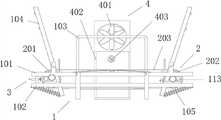
速度滑冰力量训练器,包括主体支架、传动机构、侧蹬阻力施加装置和迎风阻力施加装置;所述主体支架包括平行设置的上、下层框架,所述上层框架上设置有扶手和侧靠板,所述侧靠板有两块,其分别位于上述扶手的两侧,所述侧靠板与上层框架转动连接且各侧靠板的底端分别通过复位弹簧与上述下层框架的端部相连;所述传动机构包括安装在上、下层框架间的带轮组和绕设在所述带轮组上的传送带;所述侧蹬阻力施加装置位于上、下层框架之间且靠近所述传送带的外边缘;所述迎风阻力施加装置包括风扇,所述风扇位于上述扶手的正前方。The speed skating strength training device includes a main body support, a transmission mechanism, a side pedal resistance applying device and a windward resistance applying device; the main body support includes upper and lower frames arranged in parallel, and the upper frame is provided with handrails and side leaning plates, There are two side leaning plates, which are respectively located on both sides of the above-mentioned handrails. The said side leaning plates are rotatably connected to the upper frame and the bottom ends of each side leaning plates are respectively connected to the ends of the above-mentioned lower frame through return springs; The transmission mechanism includes a pulley set installed between the upper and lower frames and a conveyor belt wound on the pulley set; the side pedal resistance applying device is located between the upper and lower frames and is close to the outer edge of the conveyor belt ; The windward resistance applying device includes a fan, and the fan is located directly in front of the above-mentioned handrail.
所述侧蹬阻力施加装置包括阻力片、阻力片推动杆和与所述阻力片推动杆相适配的推动杆套筒,所述阻力片推动杆与推动杆套筒间为螺纹连接,所述推动杆套筒通过推动杆套筒座安装在所述上、下层框架之间,阻力片推动杆的顶端安装有阻力调节旋钮、底端安装有阻力片支架,阻力片支架与阻力片推动杆转动连接,所述阻力片安装在阻力片支架的底端。The side pedal resistance applying device comprises a resistance sheet, a resistance sheet push rod and a push rod sleeve adapted to the resistance sheet push rod, the resistance sheet push rod and the push rod sleeve are threadedly connected, the The push rod sleeve is installed between the upper and lower frames through the push rod sleeve seat, the resistance adjustment knob is installed on the top of the resistance sheet push rod, and the resistance sheet support is installed at the bottom end, and the resistance sheet support and the resistance sheet push rod rotate connected, the resistance sheet is installed at the bottom of the resistance sheet support.
所述迎风阻力施加装置还包括风扇支架,所述风扇支架上设置有多档位风速调节旋钮。The windward resistance applying device also includes a fan bracket, and the fan bracket is provided with a multi-position wind speed adjustment knob.
所述速度滑冰力量训练器还包括用于调节上述传送带的张紧结构,所述张紧结构包括张紧螺栓和张紧螺栓定位板,所述张紧螺栓定位板垂直安装在下层框架的上端面上;所述带轮组包括左带轮和右带轮,所述左、右带轮均通过带轮座安装在上、下层框架间,所述带轮座安装在下层框架的上端面上,其中左带轮或右带轮的带轮座的底板呈L型且该底板上设置有腰型孔和张紧螺栓定位孔,该底板通过穿设在所述腰型孔内的紧固螺栓安装在下层框架上。The speed skating strength training device also includes a tensioning structure for adjusting the above-mentioned conveyor belt, the tensioning structure includes a tensioning bolt and a tensioning bolt positioning plate, and the tensioning bolt positioning plate is vertically installed on the upper end surface of the lower frame above; the pulley set includes a left pulley and a right pulley, the left and right pulleys are installed between the upper and lower frames through the pulley seat, and the pulley seat is installed on the upper end surface of the lower frame, Wherein the bottom plate of the pulley seat of the left pulley or the right pulley is L-shaped and the bottom plate is provided with a waist-shaped hole and a tension bolt positioning hole, and the bottom plate is installed by fastening bolts pierced in the waist-shaped hole on the lower frame.
所述上层框架上设置有挡板,所述挡板有两块,其分别位于上述侧靠板和扶手之间。A baffle is arranged on the upper frame, and there are two baffles, which are respectively located between the above-mentioned side leaning plate and the handrail.
所述上层框架上均布有多根支撑横梁,所述支撑横梁的上方设置有弧形支撑板,所述弧形支撑板位于上述两块挡板之间。A plurality of support beams are evenly distributed on the upper frame, and an arc-shaped support plate is arranged above the support beams, and the arc-shaped support plate is located between the above-mentioned two baffle plates.
所述上层框架上设置有用于安装上述两侧靠板的侧靠板座,每块侧靠板对应两个侧靠板座,侧靠板座上开设有转轴孔,对应同一块侧靠板的两个侧靠板座的转轴孔内穿接有活动销轴,侧靠板可绕所述活动销轴旋转。The upper frame is provided with side leaning plate seats for installing the above-mentioned two side leaning plates, each side leaning plate corresponds to two side leaning plate seats, and a rotating shaft hole is opened on the side leaning plate seats, corresponding to the same side leaning plate A movable pin shaft is pierced in the rotating shaft holes of the two side leaning plate seats, and the side leaning plate can rotate around the movable pin shaft.
所述传送带为多楔带。The conveyor belt is a V-ribbed belt.
所述扶手呈U型,所述上、下层框架安装在两条支腿上,所述支腿呈U型。The armrest is U-shaped, and the upper and lower frames are installed on two supporting legs, and the supporting legs are U-shaped.
所述风扇为轴流式风扇。The fan is an axial fan.
由于采用了上述技术方案,本实用新型所取得的有益效果为:Owing to adopting above-mentioned technical scheme, the beneficial effect that the utility model obtains is:
1、本实用新型不仅满足了运动员模拟冰上实际比赛直道、弯道技术以及战术训练要求,还满足了专项训练外加阻力负荷在器械上的调整,运动员可以更科学地进行专项力量训练,提高专项力量耐力能力水平。1. The utility model not only satisfies the athletes' requirements for simulating the actual straight track, curve technology and tactical training on the ice, but also meets the special training plus the adjustment of the resistance load on the equipment. The athletes can carry out special strength training more scientifically and improve special training Strength endurance ability level.
2、本实用新型结构简单,操作方便,制作成本较低,利用本实用新型可增加运动员的蹬动力量、步频与爆发力,即可用于直道训练又可用于弯道训练。2. The utility model has the advantages of simple structure, convenient operation and low production cost. The utility model can increase the pedal power, stride frequency and explosive force of athletes, and can be used for straight track training and curve training.
附图说明Description of drawings
图1为本实用新型的结构示意图。Fig. 1 is the structural representation of the utility model.
图2为本实用新型中主体支架的结构示意图。Fig. 2 is a structural schematic diagram of the main body bracket in the utility model.
图3为本实用新型中侧蹬阻力施加装置的结构示意图。Fig. 3 is a schematic structural view of the side pedal resistance applying device in the present invention.
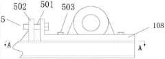
图4为本实用新型中张紧结构的示意图。Fig. 4 is a schematic diagram of the tension structure in the utility model.
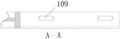
图5为图4的A-A向剖视图。Fig. 5 is a sectional view taken along line A-A of Fig. 4 .
图6为运动员利用本实用新型进行直道训练的状态示意图。Fig. 6 is a schematic diagram of a state in which an athlete uses the utility model for straight track training.
图7为运动员利用本实用新型进行弯道训练的状态示意图。Fig. 7 is a schematic diagram of a state in which an athlete uses the utility model to perform curve training.
其中,in,
1、主体支架 101、上层框架 102、下层框架 103、扶手 104、侧靠板 105、复位弹簧 106、推动杆套筒座 107、侧靠板座 108、底板 109、腰型孔 110、挡板 111、支撑横梁 112、弧形支撑板 113、带轮座 114、支腿 115、转轴孔 2、传动机构 201、左带轮 202、右带轮 203、传送带 3、侧蹬阻力施加装置 301、阻力片 302、阻力片推动杆 303、推动杆套筒 304、阻力调节旋钮 305、阻力片安装板 306、海绵夹层 307、定位螺钉 308、耳板 4、迎风阻力施加装置 401、风扇 402、风扇支架 403、多档位风速调节旋钮 5、张紧结构 501、张紧螺栓 502、张紧螺栓定位板 503、紧固螺栓1.
具体实施方式Detailed ways
下面结合附图和具体的实施例对本实用新型作进一步的详细说明,但本实用新型并不限于这些实施例。The utility model will be further described in detail below in conjunction with the accompanying drawings and specific embodiments, but the utility model is not limited to these embodiments.
如图1至图7所示,速度滑冰力量训练器,包括主体支架1、传动机构2、侧蹬阻力施加装置3和迎风阻力施加装置4。As shown in FIGS. 1 to 7 , the speed skating strength training device includes a main body bracket 1 , a
如图1、图2、图6及图7所示,所述主体支架1包括平行设置的上层框架101和下层框架102,所述上、下层框架安装在两条支腿114上,所述支腿114呈U型;所述上层框架101上设置有扶手103和侧靠板104,所述扶手103位于上层框架101的中间位置且其整体结构呈U型,该扶手103用于运动员的直道训练;所述侧靠板104有两块,其分别位于上述扶手103的两侧,各侧靠板104的底端分别通过复位弹簧105与上述下层框架102的端部相连,所述上层框架101上设置有用于安装上述两侧靠板104的侧靠板座107,每块侧靠板104对应两个侧靠板座107,侧靠板座107上开设有转轴孔115,对应同一块侧靠板104的两个侧靠板座107的转轴孔115内穿接有活动销轴,侧靠板104可绕所述活动销轴旋转,侧靠板104可根据运动员不同大小的依靠力产生不同的旋转角度,运动员的依靠力量越大,其身体的倾斜角度也越大;侧靠板104的设置用于运动员的弯道训练,当不需要进行弯道训练时,侧靠板可在复位弹簧105的作用下恢复到初始状态。As shown in Fig. 1, Fig. 2, Fig. 6 and Fig. 7, the main frame 1 includes an upper frame 101 and a lower frame 102 arranged in parallel, and the upper and lower frames are installed on two legs 114, and the support The legs 114 are U-shaped; the upper frame 101 is provided with armrests 103 and side panels 104, the armrests 103 are located in the middle of the upper frame 101 and its overall structure is U-shaped, and the armrests 103 are used for athletes' straight track training There are two side leaning plates 104, which are respectively located on both sides of the above-mentioned handrail 103, and the bottom ends of each side leaning plates 104 are respectively connected to the ends of the above-mentioned lower frame 102 through back-moving springs 105, and on the upper frame 101 There are side leaning plate seats 107 for installing the above-mentioned two side leaning plates 104, each side leaning plate 104 corresponds to two side leaning plate seats 107, and a shaft hole 115 is opened on the side leaning plate seats 107, corresponding to the same side leaning plate The rotating shaft holes 115 of the two side board seats 107 of 104 are pierced with movable pins, and the side boards 104 can rotate around the movable pins, and the side boards 104 can produce different rotations according to the different sizes of the athletes Angle, the more the athlete relies on the strength, the greater the angle of inclination of his body; Return to the original state under the action.
如图1、图2、图4及图5所示,所述传动机构包括安装在上、下层框架间的带轮组和绕设在所述带轮组上的传送带203,所述传送带203为多楔带;所述速度滑冰力量训练器还包括用于调节上述传送带的张紧结构5,所述张紧结构5包括张紧螺栓501和张紧螺栓定位板502,所述张紧螺栓定位板502垂直安装在下层框架102的上端面上;所述带轮组包括左带轮201和右带轮202,所述左、右带轮均通过带轮座113安装在上、下层框架间,所述带轮座113安装在下层框架102的上端面上,其中左带轮201或右带轮202的带轮座113的底板108呈L型且该底板上设置有腰型孔109和张紧螺栓定位孔,该底板通过穿设在所述腰型孔109内的紧固螺栓503安装在下层框架102上;本实用新型通过张紧螺栓501调节带轮在上、下层框架101上的位置,并用紧固螺栓503使带轮位置固定,从而可以调节多楔带的张紧程度。As shown in Figure 1, Figure 2, Figure 4 and Figure 5, the transmission mechanism includes a pulley set installed between the upper and lower frames and a conveyor belt 203 wound on the pulley set, the conveyor belt 203 is V-ribbed belt; the speed skating strength training device also includes a tensioning structure 5 for adjusting the above-mentioned conveyor belt, the tensioning structure 5 includes a tensioning bolt 501 and a tensioning bolt positioning plate 502, and the tensioning bolt positioning plate 502 is vertically installed on the upper end face of the lower frame 102; the pulley set includes a left pulley 201 and a right pulley 202, and the left and right pulleys are installed between the upper and lower frames through the pulley seat 113, so The pulley seat 113 is installed on the upper end surface of the lower frame 102, wherein the bottom plate 108 of the pulley seat 113 of the left pulley 201 or the right pulley 202 is L-shaped and the bottom plate is provided with waist-shaped holes 109 and tension bolts positioning hole, the bottom plate is installed on the lower frame 102 through the fastening bolt 503 in the waist hole 109; the utility model adjusts the position of the pulley on the upper and lower frame 101 through the tension bolt 501, and uses The fastening bolt 503 fixes the position of the pulley so that the tension of the V-ribbed belt can be adjusted.
如图1及图2所示,为限制运动员在直道训练时的左右滑行幅度,在上层框架101上设置挡板110,所述挡板110有两块,其分别位于上述侧靠板104和扶手103之间;运动员站在多楔带上训练时,为了防止多楔带因为运动员的重量而下垂,影响训练效果,在上层框架101上焊接三根错落的支撑横梁111,并在这三根支撑横梁111的上方设置弧形支撑板112,所述弧形支撑板112位于上述两块挡板110之间。As shown in Figure 1 and Figure 2, in order to limit the athlete's left and right sliding range when training on a straight track, a baffle 110 is set on the
本实用新型中,传送带203优选多楔带,采用多楔带作为传送带,可增大传送带203与带轮间的接触面积,从而加大摩擦力,且多楔带可使载荷沿带宽分布均匀,提高传动能力;此外,多楔带所具备的传动振动小、散热快、运转平稳、传动比大、传动效率高等特点可优化速度滑冰力量训练器的使用性能,更好的满足运动员的训练需求。In the utility model, the
如图3所示,所述侧蹬阻力施加装置3位于上、下层框架之间且靠近所述传送带203的外边缘;所述侧蹬阻力施加装置包括阻力片301、阻力片支架、阻力片推动杆302和与所述阻力片推动杆302相适配的推动杆套筒303,所述阻力片推动杆302上设置有外螺纹,推动杆套筒303的内表面上设置有与上述外螺纹相适配的内螺纹;所述阻力片推动杆302的顶端安装有阻力调节旋钮304、底端设置有第一转孔,所述阻力片支架包括阻力片安装板305和耳板308,所述耳板308有两块,其上开设有第二转孔,所述阻力片支架安装在阻力片推动杆302的底端,所述阻力片推动杆302通过穿接在所述第二转孔和第一转孔内的转轴与阻力片支架实现转动连接,所述阻力片301与阻力片安装板305之间设置有海绵夹层306,阻力片301的两端通过定位螺钉307安装在阻力片安装板305上;所述上、下层框架之间设置有推动杆套筒座106,所述推动杆套筒303通过推动杆套筒座106安装在所述上、下层框架之间。As shown in Figure 3, the side pedal resistance applying device 3 is located between the upper and lower frames and near the outer edge of the
如图1所示,所述迎风阻力施加装置4包括风扇401和风扇支架402,所述风扇401为轴流式风扇,其位于上述扶手103的正前方,所述风扇支架402上设置有多档位风速调节旋钮403,风扇401用于模拟运动员滑行运动过程中的空气阻力,其大小可通过所述多档位风速调节旋钮403进行设定。As shown in Figure 1, the windward resistance applying device 4 includes a
运动员利用本实用新型既可进行直道训练又可进行弯道训练,进行科学有效地锻炼后可增加运动员的蹬动力量、步频与爆发力。Athletes can use the utility model to carry out straight track training and curve training, and can increase the athlete's pedal power, stride frequency and explosive force after scientifically and effectively exercising.
本实用新型中未述及的部分采用或借鉴已有技术即可实现。The parts not mentioned in the utility model can be realized by adopting or referring to the prior art.
在本实用新型的描述中,需要理解的是,术语“中间”、“横向”、“上”、“下”、“前”、“后”、“左”、“右”、“竖直”、“水平”、“顶”、“底”“内”、“外”等指示的方位或位置关系为基于附图所示的方位或位置关系,仅是为了便于描述本实用新型和简化描述,而不是指示或暗示所指的装置或元件必须具有特定的方位、以特定的方位构造和操作,因此不能理解为对本实用新型的限制。In describing the present invention, it should be understood that the terms "middle", "transverse", "upper", "lower", "front", "rear", "left", "right", "vertical" , "horizontal", "top", "bottom", "inner", "outer" and other indicated orientations or positional relationships are based on the orientations or positional relationships shown in the drawings, and are only for the convenience of describing the utility model and simplifying the description. It does not indicate or imply that the device or element referred to must have a specific orientation, be constructed and operate in a specific orientation, and therefore should not be construed as limiting the present invention.
此外,术语“第一”、“第二”仅用于描述目的,而不能理解为指示或暗示相对重要性。In addition, the terms "first" and "second" are used for descriptive purposes only, and should not be understood as indicating or implying relative importance.
尽管本文中较多的使用了诸如主体支架1、上层框架101、扶手103、侧靠板座107、弧形支撑板112、传动机构2、传送带203、侧蹬阻力施加装置3、阻力调节旋钮304、海绵夹层306、迎风阻力施加装置4、多档位风速调节旋钮403等术语,但并不排除使用其它术语的可能性。使用这些术语仅仅是为了更方便地描述和解释本实用新型的本质;把它们解释成任何一种附加的限制都是与本实用新型精神相违背的。Although more used herein such as the main body support 1, the
需要进一步说明的是,本文中所描述的具体实施例仅仅是对本实用新型的精神所作的举例说明。本实用新型所属技术领域的技术人员可以对所描述的具体实施例做各种各样的修改或补充或采用类似的方式替代,但并不会偏离本实用新型的精神或者超越所附权利要求书所定义的范围。It should be further explained that the specific embodiments described herein are only illustrations for the spirit of the present utility model. Those skilled in the technical field to which the utility model belongs can make various modifications or supplements to the described specific embodiments or adopt similar methods to replace them, but they will not deviate from the spirit of the utility model or go beyond the appended claims defined range.
Claims (10)
Translated fromChinesePriority Applications (1)
| Application Number | Priority Date | Filing Date | Title |
|---|---|---|---|
| CN201320791942.7UCN203598448U (en) | 2013-12-03 | 2013-12-03 | Speed skating strength trainer |
Applications Claiming Priority (1)
| Application Number | Priority Date | Filing Date | Title |
|---|---|---|---|
| CN201320791942.7UCN203598448U (en) | 2013-12-03 | 2013-12-03 | Speed skating strength trainer |
Publications (1)
| Publication Number | Publication Date |
|---|---|
| CN203598448Utrue CN203598448U (en) | 2014-05-21 |
Family
ID=50711152
Family Applications (1)
| Application Number | Title | Priority Date | Filing Date |
|---|---|---|---|
| CN201320791942.7UExpired - Fee RelatedCN203598448U (en) | 2013-12-03 | 2013-12-03 | Speed skating strength trainer |
Country Status (1)
| Country | Link |
|---|---|
| CN (1) | CN203598448U (en) |
Cited By (3)
| Publication number | Priority date | Publication date | Assignee | Title |
|---|---|---|---|---|
| CN106994232A (en)* | 2017-04-18 | 2017-08-01 | 吴志刚 | A kind of damp type skating experiencing machine |
| CN107456722A (en)* | 2017-09-16 | 2017-12-12 | 张定宇 | A kind of strength building system based on cloud platform |
| CN115282577A (en)* | 2022-02-12 | 2022-11-04 | 齐齐哈尔大学 | A kind of auxiliary training device for speed skating |
- 2013
- 2013-12-03CNCN201320791942.7Upatent/CN203598448U/ennot_activeExpired - Fee Related
Cited By (4)
| Publication number | Priority date | Publication date | Assignee | Title |
|---|---|---|---|---|
| CN106994232A (en)* | 2017-04-18 | 2017-08-01 | 吴志刚 | A kind of damp type skating experiencing machine |
| CN107456722A (en)* | 2017-09-16 | 2017-12-12 | 张定宇 | A kind of strength building system based on cloud platform |
| CN115282577A (en)* | 2022-02-12 | 2022-11-04 | 齐齐哈尔大学 | A kind of auxiliary training device for speed skating |
| CN115282577B (en)* | 2022-02-12 | 2024-02-27 | 齐齐哈尔大学 | Auxiliary training device for speed skating movement |
Similar Documents
| Publication | Publication Date | Title |
|---|---|---|
| US9630051B2 (en) | Adjustable and swingable exercise bike | |
| CN108042982B (en) | Elasticity exercise device for sports | |
| US20070179023A1 (en) | Cross training exercise device | |
| CN203598448U (en) | Speed skating strength trainer | |
| CN110694232A (en) | A leg training device for track and field athletes | |
| CN108479011A (en) | A kind of sitting posture song leg forward swing health and fitness facilities | |
| CN110947152B (en) | Novel aerobics exercises is stepped on and is jumped training device | |
| CN103611264A (en) | Novel sitting fitness equipment | |
| CN103657031A (en) | Speed skating strength training device | |
| CN203591562U (en) | A multifunctional fitness chair equipped with auxiliary armrests | |
| CN106606839B (en) | a ski machine | |
| CN201668922U (en) | Sway competition bicycle | |
| US20070054782A1 (en) | Exercise apparatus | |
| CN207856229U (en) | A kind of Multifunctional outdoor sports equipment | |
| CN103550915A (en) | Indoor rock climbing sport equipment capable of simulating real rock wall | |
| US10688338B2 (en) | Exercise mechanism for training machine | |
| CN202666346U (en) | Novel combined type multifunction health exercise device | |
| US11305150B2 (en) | Simulated hill-climbing exercise apparatus | |
| CN110665184B (en) | A leg support frame for push-up training | |
| CN1593696A (en) | Surfing machine | |
| CN209596527U (en) | Covert rhythm training device before a kind of basketball body | |
| CN205886067U (en) | Take sit -up board's exercycle | |
| CN2717481Y (en) | swing exerciser | |
| CN109876360B (en) | Elastic trampoline is used in trampoline sportsman's training | |
| CN108815797A (en) | Lateral sliding steps exercising apparatus |
Legal Events
| Date | Code | Title | Description |
|---|---|---|---|
| C14 | Grant of patent or utility model | ||
| GR01 | Patent grant | ||
| CF01 | Termination of patent right due to non-payment of annual fee | Granted publication date:20140521 Termination date:20181203 | |
| CF01 | Termination of patent right due to non-payment of annual fee |