CN203577817U - Piston type burette - Google Patents
Piston type buretteDownload PDFInfo
- Publication number
- CN203577817U CN203577817UCN201320713593.7UCN201320713593UCN203577817UCN 203577817 UCN203577817 UCN 203577817UCN 201320713593 UCN201320713593 UCN 201320713593UCN 203577817 UCN203577817 UCN 203577817U
- Authority
- CN
- China
- Prior art keywords
- piston
- gas cylinder
- connecting rod
- baffle
- cylinder
- Prior art date
- Legal status (The legal status is an assumption and is not a legal conclusion. Google has not performed a legal analysis and makes no representation as to the accuracy of the status listed.)
- Expired - Fee Related
Links
Images
Landscapes
- Sampling And Sample Adjustment (AREA)
Abstract
Translated fromChineseDescription
Translated fromChinese技术领域technical field
本实用新型涉及一种实验室用的滴管,尤其是一种活塞式滴管。The utility model relates to a dropper for laboratories, in particular to a piston type dropper.
背景技术Background technique
胶头滴管是一种实验室中常用的化学仪器,在滴加液体试剂时使用频繁。但是,如果液体试剂粘度过大(例如丙三醇,硬脂酸,OP-10等),经常会出现胶头滴管的胶帽即使捏干瘪了也无法吸取试剂的现象,而且橡胶材质的胶帽容易老化,需要经常更换,费时费力,浪费资源。The rubber dropper is a chemical instrument commonly used in the laboratory, and it is frequently used when adding liquid reagents. However, if the viscosity of the liquid reagent is too high (such as glycerin, stearic acid, OP-10, etc.), it often occurs that the rubber cap of the rubber dropper cannot absorb the reagent even if it is pinched dry, and the rubber rubber The cap is easy to age and needs to be replaced frequently, which is time-consuming and labor-intensive, and a waste of resources.
实用新型内容Utility model content
为了克服传统的胶头滴管存在的无法吸取粘度较大的试剂和胶帽容易老化的问题,本实用新型提供了一种活塞式半自动滴管,该种活塞式半自动滴管不但不使用橡胶胶帽,而且可以轻松地吸取粘度较大的液体试剂。In order to overcome the problems that the traditional rubber dropper cannot absorb the reagent with high viscosity and the rubber cap is easy to age, the utility model provides a piston-type semi-automatic dropper, which not only does not use rubber cap, and can easily absorb viscous liquid reagents.
本实用新型所采取的技术方案是:一种活塞式滴管,包括管体、气筒、活塞以及连杆,所述活塞设置在气筒内部,所述活塞的一端与连杆连接,所述气筒底部设有开口,所述开口的直径与管体的直径相同,所述气筒内设有挡板,所述挡板位于气筒下方并与气筒底部形成间隙,所述管体通过开口插接在气筒上并抵靠在挡板上,所述气筒上与管体相对的一端设有手指着力支架,所述连杆上与活塞相对的一端设有圆形压板,所述手指着力支架与圆形压板之间的连杆部分套有弹簧。The technical scheme adopted by the utility model is: a piston-type dropper, including a pipe body, an air cylinder, a piston and a connecting rod, the piston is arranged inside the air cylinder, one end of the piston is connected with the connecting rod, and the bottom of the air cylinder An opening is provided, and the diameter of the opening is the same as that of the pipe body, and a baffle is provided inside the gas cylinder, and the baffle is located below the gas cylinder and forms a gap with the bottom of the gas cylinder, and the pipe body is inserted into the gas cylinder through the opening And lean against the baffle, the end of the gas cylinder opposite to the tube body is provided with a finger force support, the end of the connecting rod opposite to the piston is provided with a circular pressure plate, and the finger force support and the circular pressure plate The connecting rod part between is covered with spring.
优选地,所述气筒内壁和活塞表面覆盖聚四氟乙烯材料层。Preferably, the inner wall of the cylinder and the surface of the piston are covered with a polytetrafluoroethylene material layer.
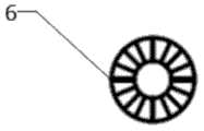
优选地,所述挡板呈圆环形。Preferably, the baffle is circular.
优选地,所述挡板与气筒底部的间隙大小为气筒高度的1/5。Preferably, the gap between the baffle plate and the bottom of the gas cylinder is 1/5 of the height of the gas cylinder.
优选地,所述挡板上方气筒的直径是管体直径的1.5倍到2倍。Preferably, the diameter of the gas cylinder above the baffle is 1.5 to 2 times the diameter of the pipe body.
优选地,所述手指着力支架的两端呈三角形。Preferably, both ends of the finger support support are triangular in shape.
本实用新型的有益效果是:滴管用活塞式结构代替了传统的橡胶胶帽,避免了经常更换胶帽造成的资源浪费,而且能够轻松地吸取粘度较大的液体试剂,气筒内壁和活塞表面的聚四氟乙烯材料具有极低的摩擦系数以及较高的抗酸碱腐蚀强度。The beneficial effects of the utility model are: the dropper uses a piston structure instead of the traditional rubber rubber cap, which avoids the waste of resources caused by frequent replacement of the rubber cap, and can easily absorb the liquid reagent with high viscosity, the inner wall of the gas cylinder and the surface of the piston. PTFE material has extremely low friction coefficient and high resistance to acid and alkali corrosion.
附图说明Description of drawings
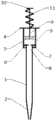
图1为本实用新型的结构示意图。Fig. 1 is the structural representation of the utility model.
图2为挡板的结构示意图。Figure 2 is a schematic structural view of the baffle.
图3为手指着力支架的俯视图。Figure 3 is a top view of the finger support.
具体实施方式Detailed ways
以下结合附图对本实用新型作进一步说明。Below in conjunction with accompanying drawing, the utility model is further described.
如图1、图2和图3所示,一种活塞式滴管,包括管体1,它的一端为圆锥形吸嘴2,另一端连接气筒3,气筒3呈空心圆柱形,气筒3与管体1相对的一端设有手指着力支架4,手指着力支架4的两端呈三角形。气筒3内设有活塞5,气筒3内壁和活塞5表面覆盖聚四氟乙烯材料层,聚四氟乙烯材料具有抗酸碱腐蚀,摩擦系数低的优点,活塞5可以在气筒3内很顺畅的来回运动。气筒3内设有圆环形挡板6,挡板6位于气筒3下方并与气筒3底部形成间隙7,间隙7的大小为气筒3高度的1/5。气筒3底部设有开口8,开口8的直径与管体1的直径相同,二者正好能组装到一起,形成密封配合,挡板6上方气筒3的直径是管体1直径的1.5倍到2倍。管体1通过开口8插接在气筒3上并抵靠在挡板6上,挡板6的作用是不会使得安装时导致管体1过于靠上而减少活塞5的活动空间。活塞5的一端设有连杆9,连杆9伸出气筒3的外部,连杆9的末端设有圆形压板10,在手指着力支架4与圆形压板10之间的连杆9部分套有弹簧11。其中,管体1由玻璃制成,气筒3、手指着力支架4、活塞5、连杆6、圆形压板10都由塑料制成。As shown in Figure 1, Figure 2 and Figure 3, a piston-type dropper includes a
使用时,将中指与食指抵在手指着力支架4的下方,拇指按动圆形压板10,此时活塞5在连杆9的推动下,压缩弹簧11向气筒3下方运动,排出气筒3内的空气,将滴管的吸嘴2浸入液体试剂中并松开拇指,此时活塞5在弹簧11的弹力作用下向气筒3上方运动,将液体试剂吸入管体1内。When in use, put the middle finger and forefinger under the support 4 of the finger, and press the
本实用新型用活塞式结构代替了传统的橡胶胶帽,避免了经常更换胶帽造成的资源浪费,而且能够轻松地吸取粘度较大的液体试剂,气筒内壁和活塞表面的聚四氟乙烯材料具有极低的摩擦系数以及较高的抗酸碱腐蚀强度。The utility model replaces the traditional rubber rubber cap with a piston structure, avoids the waste of resources caused by frequent replacement of the rubber cap, and can easily absorb liquid reagents with high viscosity. The polytetrafluoroethylene material on the inner wall of the cylinder and the surface of the piston has Very low coefficient of friction and high resistance to acid and alkali corrosion.
需要说明的是,上述说明并非是对本实用新型的限制,本实用新型也并不仅限于上述举例,本领域的普通技术人员在本实用新型的实质范围内所做出的变化、改型、添加或替换,都应涵盖于本实用新型的保护范围之内。It should be noted that the above description is not a limitation of the present utility model, and the present utility model is not limited to the above-mentioned examples, changes, modifications, additions or changes made by those skilled in the art within the essential scope of the present utility model Replacement should be covered within the protection scope of the present utility model.
Claims (6)
Translated fromChinesePriority Applications (1)
| Application Number | Priority Date | Filing Date | Title |
|---|---|---|---|
| CN201320713593.7UCN203577817U (en) | 2013-11-13 | 2013-11-13 | Piston type burette |
Applications Claiming Priority (1)
| Application Number | Priority Date | Filing Date | Title |
|---|---|---|---|
| CN201320713593.7UCN203577817U (en) | 2013-11-13 | 2013-11-13 | Piston type burette |
Publications (1)
| Publication Number | Publication Date |
|---|---|
| CN203577817Utrue CN203577817U (en) | 2014-05-07 |
Family
ID=50575797
Family Applications (1)
| Application Number | Title | Priority Date | Filing Date |
|---|---|---|---|
| CN201320713593.7UExpired - Fee RelatedCN203577817U (en) | 2013-11-13 | 2013-11-13 | Piston type burette |
Country Status (1)
| Country | Link |
|---|---|
| CN (1) | CN203577817U (en) |
Cited By (4)
| Publication number | Priority date | Publication date | Assignee | Title |
|---|---|---|---|---|
| CN105772130A (en)* | 2016-05-21 | 2016-07-20 | 周维保 | Spring burette |
| CN109738578A (en)* | 2019-01-11 | 2019-05-10 | 李冉 | A kind of gastroenterology gastric juice acidity detection device |
| CN110201731A (en)* | 2019-06-18 | 2019-09-06 | 佛山科学技术学院 | A kind of dropper |
| CN114180207A (en)* | 2021-12-10 | 2022-03-15 | 上海英宇包装科技有限公司 | A new type of 30ml dropper |
- 2013
- 2013-11-13CNCN201320713593.7Upatent/CN203577817U/ennot_activeExpired - Fee Related
Cited By (5)
| Publication number | Priority date | Publication date | Assignee | Title |
|---|---|---|---|---|
| CN105772130A (en)* | 2016-05-21 | 2016-07-20 | 周维保 | Spring burette |
| CN109738578A (en)* | 2019-01-11 | 2019-05-10 | 李冉 | A kind of gastroenterology gastric juice acidity detection device |
| CN109738578B (en)* | 2019-01-11 | 2021-06-29 | 李冉 | Gastric juice acidity detection device for digestive system department |
| CN110201731A (en)* | 2019-06-18 | 2019-09-06 | 佛山科学技术学院 | A kind of dropper |
| CN114180207A (en)* | 2021-12-10 | 2022-03-15 | 上海英宇包装科技有限公司 | A new type of 30ml dropper |
Similar Documents
| Publication | Publication Date | Title |
|---|---|---|
| CN203577817U (en) | Piston type burette | |
| CN103452944B (en) | A kind of vehicle-mounted single-acting cylinder | |
| CN205517830U (en) | Multipurpose microtitration device | |
| CN204051711U (en) | A kind of pipettor | |
| CN209173956U (en) | Micro liquid transfer device | |
| CN208439662U (en) | A kind of automatic liquid suction bottle device | |
| CN204307157U (en) | Piston component and syringe | |
| CN205109671U (en) | Rubber head burette | |
| CN203764277U (en) | Quantitative transfer pipette | |
| CN207466166U (en) | A kind of environmental protection marker | |
| CN103623878B (en) | Liquid-to-gas volumetric liquid transfer device | |
| CN203577816U (en) | Novel sucker with seal line | |
| CN211246624U (en) | A kind of anti-cross-contamination pipette tip for laboratory | |
| CN204159349U (en) | A kind of pipettor is interrupted | |
| CN208894248U (en) | A laboratory oil bubble vent joint | |
| CN203470017U (en) | Novel suction head with reinforcing ribs | |
| CN208953204U (en) | A kind of connector being easily installed | |
| CN202398372U (en) | Controllable transfer pipette | |
| CN105109251B (en) | Prepared Chinese ink collecting bottle | |
| CN205413075U (en) | Quantitative burette anticorrosives | |
| CN223122580U (en) | A quantitative detection dropper for domestic water | |
| CN107415521A (en) | A kind of pen of replaceable ink sac | |
| CN201394457Y (en) | Multi-purpose pulley-type drop pipe | |
| CN204182399U (en) | A kind of modified rubber pipette bulb | |
| CN222433229U (en) | Chip suction head adsorption structure |
Legal Events
| Date | Code | Title | Description |
|---|---|---|---|
| C14 | Grant of patent or utility model | ||
| GR01 | Patent grant | ||
| CF01 | Termination of patent right due to non-payment of annual fee | Granted publication date:20140507 Termination date:20141113 | |
| EXPY | Termination of patent right or utility model |