CN203575087U - Automatic lawn pruning vehicle - Google Patents
Automatic lawn pruning vehicleDownload PDFInfo
- Publication number
- CN203575087U CN203575087UCN201320653351.3UCN201320653351UCN203575087UCN 203575087 UCN203575087 UCN 203575087UCN 201320653351 UCN201320653351 UCN 201320653351UCN 203575087 UCN203575087 UCN 203575087U
- Authority
- CN
- China
- Prior art keywords
- wheel
- lead screw
- automatic lawn
- nut
- cutter
- Prior art date
- Legal status (The legal status is an assumption and is not a legal conclusion. Google has not performed a legal analysis and makes no representation as to the accuracy of the status listed.)
- Expired - Fee Related
Links
- 238000013138pruningMethods0.000titleabstractdescription22
- 238000006073displacement reactionMethods0.000claimsabstractdescription13
- 230000007246mechanismEffects0.000claimsabstractdescription12
- 230000001681protective effectEffects0.000claimsabstractdescription8
- 230000003287optical effectEffects0.000claimsabstractdescription4
- 238000009434installationMethods0.000claimsdescription2
- 238000004519manufacturing processMethods0.000abstract1
- 238000000034methodMethods0.000description6
- 238000009966trimmingMethods0.000description5
- 230000008569processEffects0.000description4
- 244000025254Cannabis sativaSpecies0.000description3
- 230000008878couplingEffects0.000description2
- 238000010168coupling processMethods0.000description2
- 238000005859coupling reactionMethods0.000description2
- 238000010586diagramMethods0.000description2
- 238000012986modificationMethods0.000description2
- 230000004048modificationEffects0.000description2
- 230000000694effectsEffects0.000description1
- 230000036651moodEffects0.000description1
- 238000011017operating methodMethods0.000description1
Images


Landscapes
- Harvester Elements (AREA)
Abstract
Description
Translated fromChinese技术领域technical field
本实用新型涉及一种修草车,特别涉及一种自动修草车。 The utility model relates to a grass trimming vehicle, in particular to an automatic grass trimming vehicle. the
背景技术Background technique
维护草坪的平整是非常重要的,对于大面积草坪的修剪,依靠人力完成不仅修剪的效率低下,而且对人的体力也有相当程度的要求。同时,随着修剪人员的不同或者同一修剪人员但心情不同,草坪修剪的整洁效果会出现较大波动。 It is very important to maintain the smoothness of the lawn. For the pruning of a large area of lawn, relying on manpower to complete the pruning is not only inefficient, but also requires considerable physical strength. At the same time, with different pruners or the same pruner but with different moods, the tidy effect of lawn pruning will fluctuate greatly. the
目前,市场上已有的修草机大都是人力参与的,在整个修剪过程中都需要修剪人员的操作。 At present, most of the existing lawnmowers on the market are manpower involved, and all need the operation of the mower during the whole pruning process. the
实用新型内容Utility model content
本实用新型的目的,就是针对现有的修草机存在的问题,而提供了一种自动修草车。该自动修草车在开始工作后,不再需要修剪人员的操作,同时,它能够精确地完成草坪的修剪任务。 The purpose of the utility model is to provide an automatic lawnmower aiming at the problems existing in the existing lawnmowers. After the automatic mowing vehicle starts to work, it no longer needs the operation of mowing personnel, and at the same time, it can accurately complete the mowing task of the lawn. the
为了解决上述技术问题而采取的技术方案是:该种自动修草车的特征在于,由以下几部分构成。 The technical solution adopted in order to solve the above-mentioned technical problems is: the feature of this automatic mowing vehicle is that it consists of the following parts. the
蓄电池,所述蓄电池固定在在车架尾部,为所述的自动修草车提供能量。 The storage battery is fixed at the rear of the vehicle frame to provide energy for the automatic lawn mowing vehicle. the
两个驱动电机,所述两个驱动电机,其中一个竖直安装在上箱体板外侧,其电机轴穿过上箱体板,电机轴安装在箱体中部分装有一中心轮;另一驱动电机水平安装在车架尾部,通过联轴器与后轮转轴连接。 Two drive motors, the two drive motors, one of which is installed vertically on the outside of the upper box body plate, its motor shaft passes through the upper box body plate, and the motor shaft is installed in the middle part of the box body with a center wheel; the other drive The motor is horizontally installed at the rear of the vehicle frame and connected with the rear wheel shaft through a coupling. the
四个伺服电机,所述四个伺服电机与螺母丝杠机构连接,分别安装在车架靠中间位置,呈矩形分布。 Four servo motors, the four servo motors are connected with the nut screw mechanism, are respectively installed in the middle position of the vehicle frame, and are distributed in a rectangular shape. the
三把刀具,所述三把刀具安装在箱体上,刀具转轴呈三角型分布,所述三把刀具均有四把刀片,三把刀具转轴均穿过下箱体板,且转轴位于箱体中部分均装有行星轮。 Three knives, the three knives are installed on the box body, the tool shafts are distributed in a triangle shape, each of the three knives has four blades, the three knives shafts pass through the lower box body plate, and the shafts are located in the box body The middle part is equipped with planetary gears. the
四个螺母丝杠机构,所述螺母丝杠机构螺母与下箱体板外侧固接,上、下箱体板与螺母对应位置处开有螺母内径大小的四个孔,供丝杠运动所用。 Four nut lead screw mechanisms, the nuts of the nut lead screw mechanism are fixedly connected to the outside of the lower box body plate, and four holes with the inner diameter of the nut are opened at the corresponding positions of the upper and lower box body plates and the nuts for the movement of the lead screw. the
四个车轮,所述四个车轮,呈矩形分布在车架四角,安装位置不影响刀具工作。所述四个车轮,其中两个后轮为主动轮,不可转向,两个前轮为从动轮,可转向。 The four wheels are distributed in the four corners of the vehicle frame in a rectangular shape, and the installation positions do not affect the work of the cutting tool. Described four wheels, wherein two rear wheels are driving wheels, can not steer, and two front wheels are driven wheels, can steer. the
位移传感器,所述位移传感器安装在车架下前方,正中央位置处,用来采集待修剪草坪地面凹凸信息。 A displacement sensor, the displacement sensor is installed in front of the vehicle frame, at the center position, and is used to collect ground concave-convex information of the lawn to be mowed. the
光传感器,所述光传感器安装在外壳正前方外表面的正中央位置处,用来采集前方有无待修剪草的信息。 A light sensor, which is installed at the very center of the outer surface of the housing directly in front, is used to collect information on whether there is grass to be mowed in front. the
支撑弹簧,所述支撑弹簧安装在车架正中央位置处,其一端固定在车架上,另一端与箱体连接,当箱体处于最高位置(刀具处于最高位置)时,支撑弹簧为自由伸缩状态,当箱体下降(刀具下降)时,支撑弹簧为箱体提供支持力。 Support spring, the support spring is installed at the center of the frame, one end of which is fixed on the frame, and the other end is connected to the box body, when the box body is at the highest position (the tool is at the highest position), the support spring is free to expand and contract State, when the box body is down (knife down), the support spring provides support force for the box body. the
外壳,所述外壳将所述蓄电池、驱动电机、伺服电机、螺母丝杠机构、支撑弹簧、箱体、控制器、液压缸、车架包在所述外壳内,为它们提供保护。 The casing, the casing wraps the storage battery, drive motor, servo motor, nut screw mechanism, support spring, box body, controller, hydraulic cylinder, and vehicle frame in the casing to provide protection for them. the
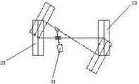
液压缸,所述液压缸安装在车架前半部分靠后位置处,位于所述两前车轮之间,通过滑块机构与前车轮转轴连接,控制前车轮转向。 A hydraulic cylinder, the hydraulic cylinder is installed at the rear position of the front half of the vehicle frame, is located between the two front wheels, is connected with the rotating shaft of the front wheels through a slider mechanism, and controls the steering of the front wheels. the
控制器,所述控制器安装在车架前半部分靠前位置处,位于所述两前车轮之间,用来接收并处理、分析所述位移传感器及光传感器采集的信号,发出控制信号,控制刀具位置及前车轮转向。 A controller, the controller is installed at the front position of the front half of the vehicle frame, between the two front wheels, and is used to receive, process and analyze the signals collected by the displacement sensor and the light sensor, send out control signals, and control Tool position and front wheel steering. the
车架,所述车架位于所述自动修草车下部,为所述伺服电机、控制器、位移传感器、驱动电机、液压缸、支撑弹簧、轴承提供支撑。所述四个车轮转轴通过轴承与车架连接。 The vehicle frame, which is located at the lower part of the automatic lawnmowing vehicle, provides support for the servo motor, controller, displacement sensor, drive motor, hydraulic cylinder, support spring and bearing. The four wheel shafts are connected with the vehicle frame through bearings. the
附图说明Description of drawings
图1为本实用新型结构图。 Fig. 1 is a structural diagram of the utility model. the
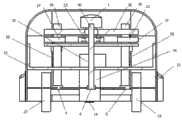
图2为本实用新型卸下外壳后正视图。 Fig. 2 is the front view of the utility model after removing the shell. the
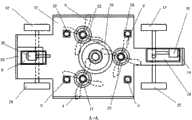
图3为本实用新型卸下外壳后俯视图。 Fig. 3 is a plan view of the utility model after the shell is removed. the
图4为本实用新型左视图。 Fig. 4 is a left view of the utility model. the
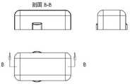
图5为本实用新型外壳三视图。 Fig. 5 is three views of the housing of the utility model. the
图6为本实用新型前轮转向机构示意图。 Fig. 6 is a schematic diagram of the front wheel steering mechanism of the present invention. the
图中:0蓄电池、1第一驱动电机、2第一伺服电机、3第二伺服电机、4第一刀具、5第二刀具、6第三刀具、7箱体、8第一螺母、9第二螺母、10第三伺服电机、11第四伺服电机、12第一车轮、13第二车轮、14位移传感器、15中心轮、16光传感器、17第一行星轮、18支撑弹簧、19第一丝杠、20第二丝杠、21外壳、22第二行星轮、23第三行星轮、24第三螺母、25第四螺母、26第三车轮、27第四车轮、28第三丝杠、29第四丝杠、30第二驱动电机、31液压缸、32控制器、33车架、34前保护罩、35后保护罩、36上箱体板、37下箱体板、38第一转轴、39第二转轴、40第三转轴。 In the figure: 0 battery, 1 first drive motor, 2 first servo motor, 3 second servo motor, 4 first cutter, 5 second cutter, 6 third cutter, 7 box, 8 first nut, 9th Two nuts, 10 third servo motor, 11 fourth servo motor, 12 first wheel, 13 second wheel, 14 displacement sensor, 15 center wheel, 16 light sensor, 17 first planetary wheel, 18 support spring, 19 first Lead screw, 20 second leading screw, 21 shell, 22 second planetary wheel, 23 third planetary wheel, 24 third nut, 25 fourth nut, 26 third wheel, 27 fourth wheel, 28 third leading screw, 29 fourth lead screw, 30 second drive motor, 31 hydraulic cylinder, 32 controller, 33 vehicle frame, 34 front protective cover, 35 rear protective cover, 36 upper box plate, 37 lower box plate, 38 first rotating shaft , 39 second rotating shaft, 40 third rotating shaft. the
具体实施方式Detailed ways
下面对本实用新型的实施例作详细说明,本实施例在以本实用新型技术方案为前提下进行实施,给出了详细的实施方式和具体的操作过程,但本实用新型的保护范围不限于下述的实施例。 The following is a detailed description of the embodiments of the present utility model. This embodiment is implemented on the premise of the technical solution of the present utility model, and detailed implementation methods and specific operating procedures are provided, but the protection scope of the present utility model is not limited to the following the described embodiment. the
实施例1。 Example 1. the
如图1、图2所示,本实施例包括:蓄电池0、第一驱动电机1、第一伺服电机2、第二伺服电机3、第一刀具4、第二刀具5、第三刀具6、箱体7、第一螺母8、第二螺母9、第三伺服电机10、第四伺服电机11、第一车轮12、第二车轮13、位移传感器14、中心轮15、光传感器16、第一行星轮17、支撑弹簧18、第一丝杠19、第二丝杠20、外壳21、第二行星轮22、第三行星轮23、第三螺母24、第四螺母25、第三车轮26、第四车轮27、第三丝杠28、第四丝杠29、第二驱动电机30、液压缸31、控制器32、车架33、前保护罩34、后保护罩35、上箱体板36、下箱体板37、第一转轴38、第二转轴39、第三转轴40。 As shown in Figures 1 and 2, this embodiment includes: a storage battery 0, a first driving motor 1, a
所述的蓄电池0固定在在车架33尾部,位于第一车轮12和第三车轮26之间。 The battery O is fixed at the rear of the vehicle frame 33 and is located between the first wheel 12 and the third wheel 26 . the
所述的第一驱动电机1,竖直安装在上箱体板36外侧,其电机轴穿过上箱体板36,电机轴安装在箱体7中的部分装有中心轮15,第一驱动电机1通过所述中心轮15及第一行星轮17控制所述第一刀具4工作,第一驱动电机1通过所述中心轮15及第二行星轮22控制所述第二刀具5工作,第一驱动电机1通过所述中心轮15及第三行星轮23控制所述第三刀具6工作。所述第一行星轮17、第二行星轮22、第三行星轮23均位于箱体7内。 The first drive motor 1 is installed vertically on the outside of the upper box body plate 36, its motor shaft passes through the upper box body plate 36, and the part where the motor shaft is installed in the box body 7 is equipped with a
所述的第二驱动电机30,水平安装在车架33尾部,其电机轴与车轮第一车轮12和第三车轮26转轴平行,所述第二驱动电机30与蓄电池0连接,同时第二驱动电机30通过联轴器与第一车轮12、第三车轮26转轴连接,控制第一车轮12、第三车轮26转动。 The second drive motor 30 is horizontally installed at the rear of the vehicle frame 33, and its motor shaft is parallel to the rotating shafts of the first wheel 12 and the third wheel 26 of the wheels. The second drive motor 30 is connected to the battery O, and the second drive The motor 30 is connected with the first wheel 12 and the third wheel 26 through a coupling to control the rotation of the first wheel 12 and the third wheel 26 . the
所述第一伺服电机2、第二伺服电机3、第三伺服电机10、第四伺服电机11分别安装在车架33靠中间位置,呈矩形分布,其中第一伺服电机2、第二伺服电机3安装在第一刀具4、第二刀具5转轴之前,第二车轮13、第四车轮27转轴之后,第三伺服电机10、第四伺服电机11安装在第三刀具6转轴之后,第一车轮12、第三车轮26转轴之前。 The
所述的第一刀具4、第二刀具5、第三刀具6安装在箱体7上,随箱体7上下移动,所述第一刀具4的第一转轴38、第二刀具5的第二转轴39、第三刀具6的第三转轴40均穿过车架33,且所述三个转轴投影至车架33上,所述投影位于车架33中间部分,且呈三角型分布,所述第一刀具4、第二刀具5、第三刀具6均有四叶刀片,刀片位于车架33与地面之间。 The first cutting tool 4, the second cutting tool 5, and the third cutting tool 6 are installed on the box body 7, and move up and down with the box body 7, the first
所述的箱体7为中空,由四个螺母丝杠机构及支撑弹簧18支撑、定位,所述第一丝杠19与第一伺服电机2连接,第二丝杠20与第二伺服电机3连接,第三丝杠28与第三伺服电机10连接,第四丝杠29与第四伺服电机11连接,所述第一丝杠19、第二丝杠20、第三丝杠28、第四丝杠29及第一伺服电机2、第二伺服电机3、第三伺服电机10、第四伺服电机11均不可移动,所述第一螺母8、第二螺母9、第三螺母24、第四螺母25与所述箱体7的下箱体板37固接,上箱体板36、下箱体板37与第一螺母8、第二螺母9、第三螺母24、第四螺母25对应位置处开有螺母内径大小的四个孔。所述支撑弹簧18位于车架33正中央位置处,其一端固定在车架33上,另一端与箱体7固接。 The box 7 is hollow, supported and positioned by four nut screw mechanisms and support springs 18, the first screw 19 is connected with the
所述的液压缸31位于车架33前半部分靠后位置处,位于所述第二车轮13、第四车轮27之间,通过滑块机构与前车轮转轴连接。 The
所述的控制器32位于车架33前半部分靠前位置处,位于所述第二车轮13、第四车轮27之间。 The controller 32 is located at the front position of the front half of the vehicle frame 33 , between the
所述的位移传感器14,位于车架33下前方,正中央位置处。所述的光传感器16位于外壳21正前方外表面的正中央位置处。 The
本方案自动修剪草坪过程如下。 The process of automatic lawn mowing in this program is as follows. the
一名修剪人员将所述的自动修草车车身摆正放在待修剪草坪外,车头朝向待修剪草坪,打开自动修草车蓄电池0开关,光传感器16、位移传感器14开始采集信号,由控制器32将采集的信号放大、处理,并由控制器32发出控制信号,前方有待修剪草坪时,控制信号控制液压缸31保持初始状态,自动修草车保持直行,前方地面凹凸信号传至第一伺服电机2、第二伺服电机3、第三伺服电机10、第四伺服电机11,第一伺服电机2通过第一丝杠19及第一螺母8、第二伺服电机3通过第二丝杠20及第二螺母9、第三伺服电机10通过第三丝杠28及第三螺母24、第四伺服电机11通过第四丝杠29及第四螺母25控制所述自动修草车箱体7位置的高低,进而控制第一刀具4、第二刀具5、第三刀具6位置的高低,以实现对草坪的精确修剪。前方无待修剪草坪时,光传感器16将信号传至控制器32,并由控制器32发出控制信号控制液压缸31运动,液压缸31带动第二车轮13、第四车轮27摆动,进而控制自动修草车转向。自动修草车转向完成,车身摆正后开始下一列待修剪草坪的精确修剪,并重复按照所述步骤工作,最终完成对整块草坪的自动修剪。 A pruning personnel puts the described automatic lawn mower vehicle body upright outside the lawn to be mowed, the head of the car faces the lawn to be mowed, turns on the battery 0 switch of the automatic lawn mower, and the light sensor 16 and the
本文中应用了具体个例对本实用新型的原理及实施方式进行了阐述,应当指出,在不脱离本实用新型原理的前提下,还可以对本实用新型进行若干改进和修饰,这些改进和修饰也应包含在本实用新型权利要求的保护范围内。 In this paper, specific examples are used to illustrate the principle and implementation of the utility model. It should be pointed out that without departing from the principle of the utility model, some improvements and modifications can also be made to the utility model, and these improvements and modifications should also be applied. Included in the scope of protection of the claims of the utility model. the
Claims (4)
Translated fromChinesePriority Applications (1)
| Application Number | Priority Date | Filing Date | Title |
|---|---|---|---|
| CN201320653351.3UCN203575087U (en) | 2013-10-23 | 2013-10-23 | Automatic lawn pruning vehicle |
Applications Claiming Priority (1)
| Application Number | Priority Date | Filing Date | Title |
|---|---|---|---|
| CN201320653351.3UCN203575087U (en) | 2013-10-23 | 2013-10-23 | Automatic lawn pruning vehicle |
Publications (1)
| Publication Number | Publication Date |
|---|---|
| CN203575087Utrue CN203575087U (en) | 2014-05-07 |
Family
ID=50573086
Family Applications (1)
| Application Number | Title | Priority Date | Filing Date |
|---|---|---|---|
| CN201320653351.3UExpired - Fee RelatedCN203575087U (en) | 2013-10-23 | 2013-10-23 | Automatic lawn pruning vehicle |
Country Status (1)
| Country | Link |
|---|---|
| CN (1) | CN203575087U (en) |
Cited By (10)
| Publication number | Priority date | Publication date | Assignee | Title |
|---|---|---|---|---|
| CN104904504A (en)* | 2015-06-12 | 2015-09-16 | 洛阳理工学院 | Lawn graphic pruning machine |
| CN105532167A (en)* | 2016-02-16 | 2016-05-04 | 廖伟城 | Efficient lawn mowing equipment |
| CN108496523A (en)* | 2018-03-28 | 2018-09-07 | 张冠 | A kind of Remote Control Automatic cutting on lawn and the method trimmed safely |
| CN106342469B (en)* | 2016-10-28 | 2019-03-22 | 洛阳理工学院 | A kind of intelligent grass-removing |
| US11172605B2 (en) | 2016-06-30 | 2021-11-16 | Tti (Macao Commercial Offshore) Limited | Autonomous lawn mower and a system for navigating thereof |
| US11172608B2 (en) | 2016-06-30 | 2021-11-16 | Tti (Macao Commercial Offshore) Limited | Autonomous lawn mower and a system for navigating thereof |
| US12296694B2 (en) | 2021-03-10 | 2025-05-13 | Techtronic Cordless Gp | Lawnmowers |
| US12369509B2 (en) | 2022-07-19 | 2025-07-29 | Techtronic Cordless Gp | Display for controlling robotic tool |
| US12425197B2 (en) | 2022-07-29 | 2025-09-23 | Techtronic Cordless Gp | Generation of a cryptography key for a robotic garden tool |
| US12443180B2 (en) | 2022-11-09 | 2025-10-14 | Techtronic Cordless Gp | Robotic lawn mowers |
- 2013
- 2013-10-23CNCN201320653351.3Upatent/CN203575087U/ennot_activeExpired - Fee Related
Cited By (13)
| Publication number | Priority date | Publication date | Assignee | Title |
|---|---|---|---|---|
| CN104904504B (en)* | 2015-06-12 | 2018-01-26 | 洛阳理工学院 | A lawn graphic trimmer |
| CN104904504A (en)* | 2015-06-12 | 2015-09-16 | 洛阳理工学院 | Lawn graphic pruning machine |
| CN105532167A (en)* | 2016-02-16 | 2016-05-04 | 廖伟城 | Efficient lawn mowing equipment |
| US11172608B2 (en) | 2016-06-30 | 2021-11-16 | Tti (Macao Commercial Offshore) Limited | Autonomous lawn mower and a system for navigating thereof |
| US11832552B2 (en) | 2016-06-30 | 2023-12-05 | Techtronic Outdoor Products Technology Limited | Autonomous lawn mower and a system for navigating thereof |
| US11172605B2 (en) | 2016-06-30 | 2021-11-16 | Tti (Macao Commercial Offshore) Limited | Autonomous lawn mower and a system for navigating thereof |
| CN106342469B (en)* | 2016-10-28 | 2019-03-22 | 洛阳理工学院 | A kind of intelligent grass-removing |
| CN108496523A (en)* | 2018-03-28 | 2018-09-07 | 张冠 | A kind of Remote Control Automatic cutting on lawn and the method trimmed safely |
| CN108496523B (en)* | 2018-03-28 | 2021-03-26 | 中实翊(福建)建设工程有限公司 | Method for remotely and automatically cutting and safely trimming lawn |
| US12296694B2 (en) | 2021-03-10 | 2025-05-13 | Techtronic Cordless Gp | Lawnmowers |
| US12369509B2 (en) | 2022-07-19 | 2025-07-29 | Techtronic Cordless Gp | Display for controlling robotic tool |
| US12425197B2 (en) | 2022-07-29 | 2025-09-23 | Techtronic Cordless Gp | Generation of a cryptography key for a robotic garden tool |
| US12443180B2 (en) | 2022-11-09 | 2025-10-14 | Techtronic Cordless Gp | Robotic lawn mowers |
Similar Documents
| Publication | Publication Date | Title |
|---|---|---|
| CN203575087U (en) | Automatic lawn pruning vehicle | |
| CN104798528B (en) | Flying method automatic mower and mowing group | |
| CN101849481A (en) | A vehicle-mounted hedge trimmer | |
| CN107567802A (en) | A kind of solar energy intelligent drawing grass-removing robot | |
| CN108673464A (en) | A kind of automatic pruning device of rose | |
| CN112894961B (en) | A film-breaking machine for agricultural planting based on AI artificial intelligence control | |
| CN206227015U (en) | A kind of hay mover | |
| CN206611786U (en) | Hay mover | |
| CN200959731Y (en) | Mower | |
| CN219087825U (en) | A mowing robot with independent suspension mechanism | |
| CN210841314U (en) | A new type of automatic forehead weeder | |
| CN209017403U (en) | A weeding robot for orchard weeding | |
| CN207219443U (en) | Electronic riding type mower | |
| CN205124349U (en) | Flying method is from motor mower and crowd that mows | |
| CN108476716A (en) | A kind of cart type grass trimmer | |
| CN217292513U (en) | Automatic film breaking device of film laminating machine | |
| CN112470692A (en) | Intelligent hybrid rice male parent crushing robot | |
| CN219248590U (en) | a lawn mowing robot | |
| CN109220291B (en) | A hand-push shrub pruning machine | |
| CN103314702A (en) | Rotary drum type mower | |
| CN208353932U (en) | A kind of grass-removing robot with smart steering mechanism | |
| CN207235541U (en) | A kind of automatic flowers and plants trimmer | |
| CN202857313U (en) | Car type grass cutter | |
| CN207460896U (en) | Head structure of double-blade brush cutter | |
| CN201066996Y (en) | Manual lawn trimmer |
Legal Events
| Date | Code | Title | Description |
|---|---|---|---|
| C14 | Grant of patent or utility model | ||
| GR01 | Patent grant | ||
| CF01 | Termination of patent right due to non-payment of annual fee | Granted publication date:20140507 Termination date:20141023 | |
| EXPY | Termination of patent right or utility model |