CN203433140U - Light guide plate, backlight module and arc display device - Google Patents
Light guide plate, backlight module and arc display deviceDownload PDFInfo
- Publication number
- CN203433140U CN203433140UCN201320506755.XUCN201320506755UCN203433140UCN 203433140 UCN203433140 UCN 203433140UCN 201320506755 UCN201320506755 UCN 201320506755UCN 203433140 UCN203433140 UCN 203433140U
- Authority
- CN
- China
- Prior art keywords
- light guide
- light
- guide plate
- backlight module
- guide structure
- Prior art date
- Legal status (The legal status is an assumption and is not a legal conclusion. Google has not performed a legal analysis and makes no representation as to the accuracy of the status listed.)
- Expired - Fee Related
Links
Images


Landscapes
- Planar Illumination Modules (AREA)
Abstract
Translated fromChineseDescription
Translated fromChinese技术领域technical field
本实用新型设计显示领域,尤其涉及一种导光板、背光模组及弧形显示装置。The utility model relates to the design display field, in particular to a light guide plate, a backlight module and an arc display device.
背景技术Background technique
在有源显示装置中,通常需要背光模组提供光源;背光模组通常包括导光板以及发光元件。所述导光板通常用以将发光元件发射出的点光或线光转换成面光。In an active display device, a backlight module is usually required to provide a light source; the backlight module usually includes a light guide plate and a light emitting element. The light guide plate is generally used to convert the point light or line light emitted by the light emitting element into surface light.
因为场地和应用环境的变化,平面显示器已经不能满足需求了,弧形显示装置越来越受到重视,而现有的背光模组都是针对于平面显示装置而设置的,而没有专门的可以提供均弧形光源的背光模组。直接使用适用于平面显示装置设计的背光模组用于构成弧形显示装置,将导致局部偏暗的显现,尤其是当所述弧形显示装置的面积较大且弯曲的弧度较大时,尤为明显。Due to changes in venues and application environments, flat-panel displays can no longer meet the needs, and more and more attention has been paid to curved display devices. However, the existing backlight modules are all designed for flat-panel display devices, and there is no special one that can provide them. A backlight module with a uniform arc light source. Directly using a backlight module suitable for the design of a flat display device to form a curved display device will result in a partial dark appearance, especially when the curved display device has a large area and a large curved arc. obvious.
实用新型内容Utility model content
(一)实用新型目的(1) Purpose of utility model
针对上述问题,本实用新型旨在提供一种可以提供弧形出光面的、显示效果好的导光板、背光模组及弧形显示装置。In view of the above problems, the utility model aims to provide a light guide plate, a backlight module and a curved display device which can provide a curved light emitting surface and have good display effect.
(二)技术方案(2) Technical solution
为达上述目的,本实用新型导光板,包括若干并列设置的第一导光结构;To achieve the above purpose, the light guide plate of the present invention includes several first light guide structures arranged side by side;
若干所述第一导光结构组合后形成的出光面为弧形;The light-emitting surface formed by the combination of several first light-guiding structures is arc-shaped;
相邻两个所述第一导光结构之间间隙内设有折射率小于所述第一导光结构折射率的填充层。A filling layer having a refractive index lower than that of the first light guiding structures is provided in the gap between two adjacent first light guiding structures.
进一步地,还包括第二导光结构;Further, it also includes a second light guiding structure;
所述第二导光结构位于所述第一导光结构背离所述出光面的一侧;且所述第二导光结构的至少一个侧面构成所述导光板的入光面。The second light guide structure is located on a side of the first light guide structure away from the light exit surface; and at least one side surface of the second light guide structure constitutes a light incident surface of the light guide plate.
进一步地,所述第一导光结构与所述第二导光结构通过透明光学胶粘合连接。Further, the first light guiding structure is bonded to the second light guiding structure through transparent optical glue.
进一步地,所述第二导光结构在背离所述第一导光结构的表面设有若干凹槽;且若干所述凹槽形成凹槽矩阵;所述填充层向所述第二导光结构的投影位于所述凹槽矩阵的行间隙或列间隙内。Further, the second light guiding structure is provided with several grooves on the surface away from the first light guiding structure; and several of the grooves form a groove matrix; the filling layer faces toward the second light guiding structure The projections of are located within the row or column gaps of the groove matrix.
进一步地,所述凹槽为倒V形凹槽或半球形凹槽。Further, the groove is an inverted V-shaped groove or a hemispherical groove.
为达上述目的,本实用新型背光模组,包括如上所述的导光板。To achieve the above purpose, the backlight module of the present invention includes the above-mentioned light guide plate.
进一步地,所述导光板为若干块,且所述导光板之间按各自出光面的弧度拼接形成所述背光模组的弧形出光面。Further, the light guide plate is composed of several pieces, and the light guide plates are spliced according to the arc of the respective light-emitting surfaces to form the arc-shaped light-emitting surface of the backlight module.
进一步地,所述背光模组还包括若干发光部件;所述发光部件位于所述导光板的下方。Further, the backlight module further includes several light emitting components; the light emitting components are located under the light guide plate.
为达上述目的,本实用新型背光模组,包括如上所述的导光板。To achieve the above purpose, the backlight module of the present invention includes the above-mentioned light guide plate.
优选地,所述导光板为若干块,且所述导光板之间按各自出光面的弧度拼接形成所述背光模组的弧形出光面。Preferably, there are several light guide plates, and the light guide plates are spliced according to the arc of the respective light-emitting surfaces to form the arc-shaped light-emitting surface of the backlight module.
优选地,还包括若干发光元件;每一个所述导光板的入光面均设有所述发光元件。Preferably, several light emitting elements are also included; the light incident surface of each light guide plate is provided with the light emitting elements.
为达上述目的,本实用新型弧形显示装置,包括如上所述的背光模组。To achieve the above purpose, the curved display device of the present invention includes the above-mentioned backlight module.
(三)本实用新型的导光板、背光模组及弧形显示装置有益效果(3) Beneficial effects of the light guide plate, backlight module and curved display device of the present invention
本实用新型的导光板、背光模组及弧形显示装置,通过第一导光结构组合形成了一个弧形的出光面,从而可以应用其组成的背光模组的发光面呈弧形,从而可以更好的与显示面板相配合,形成弧形显示器,从而不会造成弧形显示面板与背光模组之间的间距各处不同,从而导致的间距大的局部偏暗的现象,从而提升了显示效果,且打破了弧形显示器无专用的背光模组的空白。The light guide plate, backlight module and arc-shaped display device of the utility model form an arc-shaped light-emitting surface through the combination of the first light-guiding structure, so that the light-emitting surface of the backlight module composed of it can be arc-shaped, so that Better cooperate with the display panel to form a curved display, so that the distance between the curved display panel and the backlight module will not be different everywhere, resulting in the phenomenon of partial darkening with a large distance, thus improving the display effect, and break the blank of the curved display without a dedicated backlight module.
附图说明Description of drawings
图1为本实用新型实施例一所述的导光板的侧视结构示意图;Fig. 1 is a side view structural schematic diagram of the light guide plate described in
图2为本实用新型实施例二所述的导光板的侧视结构示意图;Fig. 2 is a schematic side view structural diagram of the light guide plate described in Embodiment 2 of the present invention;
图3为本实用新型实施例二所述的导光板的侧视局部结构示意图之一;Fig. 3 is one of the side view partial structural schematic diagrams of the light guide plate described in the second embodiment of the present invention;
图4为本实用新型实施例二所述的导光板的侧视局部结构示意图之二;Fig. 4 is the second partial structural schematic diagram of the side view of the light guide plate described in the second embodiment of the utility model;
图5为本实用新型实施例三所述的背光模组的侧视结构示意图之一;Fig. 5 is one of the side view structural diagrams of the backlight module described in the third embodiment of the present invention;
图6为本实用新型实施例三所述的背光模组的侧视结构示意图之二;Fig. 6 is the second schematic diagram of the side view structure of the backlight module described in the third embodiment of the present invention;
图7为本实用新型实施例四所述的背光模组的侧视结构示意图之一;Fig. 7 is one of the side view structural diagrams of the backlight module described in Embodiment 4 of the present utility model;
图8为本实用新型实施例四所述的背光模组的侧视结构示意图之二。FIG. 8 is the second schematic diagram of the side view structure of the backlight module according to the fourth embodiment of the present invention.
具体实施方式Detailed ways
下面结合说明书附图以及实施例对本实用新型做进一步的说明。The utility model will be further described below in conjunction with the accompanying drawings and embodiments of the description.
实施例一:Embodiment one:
如图1所示,本实施例所述导光板,包括若干并列设置的第一导光结构;具体的包括第一导光结构110和第一导光结构120;As shown in FIG. 1 , the light guide plate in this embodiment includes several first light guide structures arranged side by side; specifically, it includes a first
若干所述第一导光结构组合后形成的出光面为140弧形;The light exit surface formed by the combination of several first light guide structures is 140 arc-shaped;
相邻两个所述第一导光结构之间间隙内设有折射率小于所述第一导光结构折射率的填充层。如图1第一导光结构110和第一导光结构120之间间隙内设有填充层130;所述填充层130的折射率小于所述第一导光结构的折射率,从而在所述第一导光结构内的光线将发生全反射,最终将从出光面140射出。A filling layer having a refractive index lower than that of the first light guiding structures is provided in the gap between two adjacent first light guiding structures. As shown in Figure 1, a
从图示可知,本实施例所述的导光板的出光面140为弧形,而传统的导光板出光面都是平面的,从而本实施例可以用于制作弧形显示装置,从而弧形显示装置的显示面板的各部分与导光板的出光面的距离一致,从而不会出现显示时的局部暗影。It can be seen from the figure that the light-emitting
在具体的实施过程中,所述第一导光结构的材质可以是PC、有机玻璃或光学玻璃等光学部件。在具体的制作过程中所述出光面的弧度的大小可以根据需要调整每一个第一导光结构出光面的曲率来实现。In a specific implementation process, the material of the first light guiding structure may be optical components such as PC, plexiglass or optical glass. In a specific manufacturing process, the curvature of the light-emitting surface can be realized by adjusting the curvature of the light-emitting surface of each first light guide structure as required.
实施例二:Embodiment two:
如图2所示,本实施例所述的导光板,包括若干并列设置的第一导光结构以及第二导光结构240;As shown in FIG. 2 , the light guide plate described in this embodiment includes several first light guide structures and second light guide structures 240 arranged side by side;
若干所述第一导光结构组合后形成的出光面250为弧形;具体的如所述第一导光结构210和第一导光结构220;The light exit surface 250 formed by the combination of several first light guide structures is arc-shaped; specifically, the first light guide structure 210 and the first light guide structure 220;
相邻两个所述第一导光结构之间间隙内设有折射率小于所述导光结构的折射率的填充层;如图2所示所述第一导光结构210与所述第一导光结构220之间的间隙内设有填充层230A filling layer with a refractive index lower than that of the light guide structures is provided in the gap between two adjacent first light guide structures; as shown in FIG. 2 , the first light guide structure 210 and the first light guide structure A filling layer 230 is provided in the gap between the light guide structures 220
所述第二导光结构240位于所述第一导光结构与出光面相对的一侧;且所述第二导光结构240的至少一个侧面构成所述导光板的入光面,图2中所述的入光面为所述第二导光结构240的侧面260。所述第二导光结构240包括5个面,其中4个侧面;所述4个侧面的任一一个或多个都可以作为本实施例所述导光板的入光面。The second light guide structure 240 is located on the side opposite to the light exit surface of the first light guide structure; and at least one side of the second light guide structure 240 constitutes the light incident surface of the light guide plate, as shown in FIG. 2 The light incident surface is the side surface 260 of the second light guiding structure 240 . The second light guide structure 240 includes 5 surfaces, including 4 sides; any one or more of the 4 sides can be used as the light incident surface of the light guide plate in this embodiment.
在本实施例中通过所述第二导光结构的设置,可以将侧面的光线导入并最终在所述出光面250中射出,从而可以用于构建侧入式背光模组,且具有结构简单,制作简便的优点。所述第二导光结构的材质可以是PC、有机玻璃或光学玻璃等光学部件。In this embodiment, through the setting of the second light guide structure, the side light can be introduced and finally emitted in the light exit surface 250, so that it can be used to build a side-type backlight module, and has a simple structure, The advantage of being easy to make. The material of the second light guiding structure may be optical components such as PC, plexiglass or optical glass.
在具体的实施过程中,所述第一导光结构与所述第二导光结构可以是相互分离的,也可以是相互固定的,且固定的结构有多种,可以是卡勾或插隼连接等连接结构,在本实施例中优先选用采用透明光学胶粘合连接,采用这种连接方式对第一导光结构以及第二导光结构本身不用做形状的改变,只需贴服或涂覆光学胶即可,实现更加简便快捷。In a specific implementation process, the first light guiding structure and the second light guiding structure can be separated from each other, or can be fixed to each other, and there are many kinds of fixing structures, which can be a hook or a plug Connection structure such as connection, in this embodiment, it is preferred to use transparent optical glue to bond and connect. Using this connection method does not need to change the shape of the first light guide structure and the second light guide structure itself, only need to stick or paint Just cover with optical glue, which is easier and faster to realize.
在具体的实施过程中,所述第二导光结构可以选用现有的任一一种平面的导光板。且所述第二导光结构分为至少两种:In a specific implementation process, the second light guide structure can be any existing planar light guide plate. And the second light guide structure is divided into at least two types:
第一种;所述第二导光结构包括一个平滑的光学板,在所述光学板的下表面——与其出光面相对设置的一面,设有印刷的油墨网点;The first type: the second light guide structure includes a smooth optical plate, on the lower surface of the optical plate—the side opposite to the light-emitting surface, there are printed ink dots;
第二种:所述第二导光结构包括一个平滑光学板,在所述光学板的下表面——与其出光面相对设置的一面,设有向上的凹槽;所述凹槽改变了光线的角度,从而使得光线可以从其出光面射出;The second type: the second light guide structure includes a smooth optical plate, on the lower surface of the optical plate—the side opposite to the light-emitting surface, there is an upward groove; the groove changes the direction of light Angle, so that light can be emitted from its light-emitting surface;
在本实施例中优选第二种导光板;具体的,所述第二导光结构的下表面设有若干凹槽,且若干所述凹槽组合后形成凹槽矩阵;所述填充层向所述第二导光结构的投影位于所述凹槽矩阵的行间隙或列间隙内。为了尽可能的提高光光线的利用率,从而将所述填充层与所述凹槽在第二导光结构的下表面所在的平面内投影错开设置,以使从凹槽射出的光线尽可能从所述第一导光结构射出。所述第二导光结构的下表面所在的平面内的投影为将所述第二导光结构水平放置时,将所述填充层垂直于水平面从上往下投影,其投影与所述第二导光结构上的凹槽是相互错开的,由于凹槽形成了整列,故所述填充层的投影将位于凹槽的行间隙或列间隙中。In this embodiment, the second light guide plate is preferred; specifically, the lower surface of the second light guide structure is provided with several grooves, and the combination of several grooves forms a groove matrix; The projection of the second light guiding structure is located in the row gap or column gap of the groove matrix. In order to improve the utilization rate of light rays as much as possible, the projection of the filling layer and the groove on the plane where the lower surface of the second light guiding structure is located is staggered, so that the light emitted from the groove The first light guide structure is emitted. The projection in the plane where the lower surface of the second light guide structure is located is that when the second light guide structure is placed horizontally, the filling layer is projected from top to bottom perpendicular to the horizontal plane, and its projection is the same as that of the second light guide structure. The grooves on the light guide structure are staggered from each other, and since the grooves form a complete column, the projection of the filling layer will be located in the row gap or the column gap of the grooves.
具体的所述凹槽的形状有多种,大小也可根据需求设置,在本实施例中提供两种优选结构:所述凹槽为如图3所示的半球形1101,或者所述凹槽为如图4所示的倒V形1102。对应的图3中包括第一导光结构11、13,在第一导光结构11与第一导光结构13之间设有填充层12。对应的图4中包括第一导光结构21、23,在第一导光结构21与第一导光结构23之间设有填充层22。由于这两种形状的结构比较规则,因此制作简便。There are many shapes of the specific groove, and the size can also be set according to requirements. In this embodiment, two preferred structures are provided: the groove is hemispherical 1101 as shown in Figure 3, or the groove It is an
在具体的实施过程中所述凹槽的大小、深度和密度可以根据所需照度以及照度的均匀性进行设置。其中图3-图4中位于第二导光结构中的所示箭头均为射向凹槽的光线,在凹槽的作用下不在第二导光结构中发生全反射,而是从所凹槽对应处的所述第二导光结构的上表面射出,继而在所述第一导光结构与填充层之间中发生全反射,最终从第一导光结构的弧形出光面射出。In a specific implementation process, the size, depth and density of the grooves can be set according to the required illuminance and uniformity of illuminance. Wherein the arrows shown in the second light guide structure in Figure 3-Figure 4 are the light rays directed to the groove, under the action of the groove, the total reflection does not occur in the second light guide structure, but from the groove The corresponding light emits from the upper surface of the second light guiding structure, then undergoes total reflection between the first light guiding structure and the filling layer, and finally emits from the arc-shaped light emitting surface of the first light guiding structure.
综合实施例一至少实施例二,本实用新型所述的导光板的出光面为弧形,开创性地设计了弧形导光结构,且有利于提高弧形显示装置的显示效果。Combining
实施例三:Embodiment three:
如图5所示,本实施例所述的背光模组包括如实施例一所述的导光板310。导光板310负责光线的传导,同时将点光源的光线或线光源的光线转换成面光,以提供一个发光面。在本实施例中所述的导光板310可以为将导光板310下方的光线往上传导形成一个向上的弧形面光源;本实施例的背光模组的发光面330具体可以呈弧形。As shown in FIG. 5 , the backlight module described in this embodiment includes the
在所述导光板310的下方可以设有若干发光元件320;所述发光元件320发出的光线射入第一导光结构以及填充层中,由于填充层的折射率低于所述第一导光结构的折射率,从而位于第一导光结构中的光线发生全反射,最终从出光面330射出,因此使得光源的有效利用率被提高。A number of
所述发光元件可以LED——发光二级管、CCFL——冷阴极管以及LD——激光元件等发光部件。The light-emitting element can be light-emitting components such as LED—light-emitting diode, CCFL—cold cathode tube, and LD—laser element.
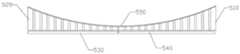
作为本实施例的进一步改进,所述背光模组中所述导光板可以为若干块,且各块导光板之间可以按各自出光面的弧度拼接形成所述背光模组的弧形出光面。如图6所示,所述背光模组包括导光板510以及导光板520,导光板510和导光板520拼接形成了背光模组的弧形出光面550;其中所述背光模组中还包括发光元件530以及发光元件540。As a further improvement of this embodiment, there may be several light guide plates in the backlight module, and each light guide plate may be spliced according to the arc of the respective light-emitting surfaces to form an arc-shaped light-emitting surface of the backlight module. As shown in Figure 6, the backlight module includes a
在本实施例中所述导光板的数目可以为2块,还可是4块或5块,具体可以根据导光板本身大小以及背光模组的大小进行拼接。所拼接方式可以带状拼接——即导光板之间排成行或列,也可以是块状拼接最终形成导光板的阵列。In this embodiment, the number of light guide plates can be 2, 4 or 5, and splicing can be performed according to the size of the light guide plates themselves and the size of the backlight module. The splicing method can be strip splicing—that is, the light guide plates are arranged in rows or columns, or block splicing to finally form an array of light guide plates.
在具体的实施过程中是,所述背光模组在所述第一导光结构的出光面上还可以设有棱镜膜、散射膜等光学膜材,以使光线进一步的均匀分布。In a specific implementation process, the backlight module may also be provided with optical film materials such as prism film and scattering film on the light exit surface of the first light guide structure, so as to further uniformly distribute light.
本实施例所述的背光模组为弧形背光模组,应用于弧形显示器时不会产生局部的亮度较低的现象。在具体的实现过程中,所述导光板的数目可以根据导光板本身的大小以及背光模组本身的大小进行设置。The backlight module described in this embodiment is an arc-shaped backlight module, and when applied to an arc-shaped display, local low brightness will not occur. In a specific implementation process, the number of the light guide plates can be set according to the size of the light guide plates themselves and the size of the backlight module itself.
实施例四:Embodiment four:
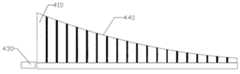
如图7所示,本实施例背光模组,包括如实施例二所述的导光板410以及发光元件420,所述发光元件420位于所述导光板的第二导光结构的侧面。本实施例提供的是一种发光元件在侧面的侧入式背光模组。As shown in FIG. 7 , the backlight module of this embodiment includes the
将发光元件420设置在所述的导光板的侧面有利于降低背光模组的厚度,从而有利于背光模组的薄型化,且由于弧形显示器背光模组的出光面是弧形的,能很好与显示面板组合形成弧形显示器,从而避免局部暗影的现象产生。Arranging the light-emitting element 420 on the side of the light guide plate is conducive to reducing the thickness of the backlight module, thereby facilitating the thinning of the backlight module, and because the light-emitting surface of the backlight module of the curved display is curved, it can be easily It is best to combine with the display panel to form a curved display, so as to avoid the phenomenon of local shadows.
作为本实施例的进一步改进,本实施例所述的背光模组中的所述导光板可以为若干块,且所述导光板之间可以按各自出光面的弧度拼接形成所述背光模组的弧形出光面。As a further improvement of this embodiment, the light guide plates in the backlight module described in this embodiment can be several pieces, and the light guide plates can be spliced according to the arcs of their respective light-emitting surfaces to form the backlight module. Curved surface.
具体的如图8所示,所述背光模组包括3块实施例二所述的导光板,分别是导光板610、导光板630以及导光板650;对应设置所述导光板610的入光面的发光元件620;对应设置所述导光板630的入光面的发光元件640;对应设置所述导光板650的入光面的发光元件660;在本实施例中所述导光板的数目还可以为3块,还可是4块或5块,具体可以根据导光板本身大小以及背光模组的大小进行拼接。所拼接方式可以带状拼接——即导光板之间排成行或列,也可以是块状拼接最终形成导光板的矩阵。Specifically, as shown in FIG. 8, the backlight module includes three light guide plates described in Embodiment 2, which are light guide plate 610, light guide plate 630, and light guide plate 650; The light-emitting element 620; the light-emitting element 640 corresponding to the light incident surface of the light guide plate 630; the light-emitting element 660 corresponding to the light incident surface of the light guide plate 650; the number of the light guide plate in this embodiment can also be There are 3 pieces, 4 pieces or 5 pieces, which can be spliced according to the size of the light guide plate itself and the size of the backlight module. The splicing method can be strip splicing—that is, the light guide plates are arranged in rows or columns, or it can be block splicing to finally form a matrix of light guide plates.
在具体的应用过程中在所述背光模组的出光面还可以设有各种光学膜材、如棱镜膜片、散射膜片等光学部件,以提高亮度或光线均匀度。In a specific application process, various optical film materials, such as prism film, scattering film and other optical components, may be provided on the light emitting surface of the backlight module to improve brightness or light uniformity.
本实施例所述的背光模组可以用于提供弧形的光源,与弧形的显示面板配后,形成一个弧形的显示装置,背光亮度均匀,显示效果佳,且结构简单,制作简便。The backlight module described in this embodiment can be used to provide an arc-shaped light source. After matching with an arc-shaped display panel, an arc-shaped display device is formed. The backlight brightness is uniform, the display effect is good, and the structure is simple and easy to manufacture.
实施例五:Embodiment five:
本实施例弧形显示装置,包括如实施例三或实施例四所述的背光模组。所述弧形显示装置还包括弧形显示面板,所述弧形显示面板位于所述背光模组的出光面。所述显示面板各处与背光膜组件各处的距离均等,在背光模组发出的是均一性光的条件下,显示面板各处接收到的亮度也具有均一性,因此不会形成局部暗影等不良,具有显示效果佳的优点。The curved display device of this embodiment includes the backlight module as described in Embodiment 3 or Embodiment 4. The curved display device further includes a curved display panel, and the curved display panel is located on the light emitting surface of the backlight module. The distances between all parts of the display panel and the backlight film assembly are equal, and under the condition that the backlight module emits uniform light, the brightness received by all parts of the display panel is also uniform, so local shadows and the like will not be formed. Bad, with the advantage of good display effect.
所述显示面板优选为液晶显示面板。所述弧形显示装置可以是电视机、电子屏幕等显示装置,具有结构简单、显示效果佳的优点。The display panel is preferably a liquid crystal display panel. The arc-shaped display device can be a display device such as a television, an electronic screen, etc., and has the advantages of simple structure and good display effect.
以上实施方式仅用于说明本实用新型,而并非对本实用新型的限制,有关技术领域的普通技术人员,在不脱离本实用新型的精神和范围的情况下,还可以做出各种变化和变型,因此所有等同的技术方案也属于本实用新型的范畴,本实用新型的专利保护范围应由权利要求限定。The above embodiments are only used to illustrate the utility model, but not to limit the utility model. Those of ordinary skill in the relevant technical fields can also make various changes and modifications without departing from the spirit and scope of the utility model. , so all equivalent technical solutions also belong to the category of the utility model, and the patent protection scope of the utility model should be defined by the claims.
Claims (12)
Priority Applications (1)
| Application Number | Priority Date | Filing Date | Title |
|---|---|---|---|
| CN201320506755.XUCN203433140U (en) | 2013-08-19 | 2013-08-19 | Light guide plate, backlight module and arc display device |
Applications Claiming Priority (1)
| Application Number | Priority Date | Filing Date | Title |
|---|---|---|---|
| CN201320506755.XUCN203433140U (en) | 2013-08-19 | 2013-08-19 | Light guide plate, backlight module and arc display device |
Publications (1)
| Publication Number | Publication Date |
|---|---|
| CN203433140Utrue CN203433140U (en) | 2014-02-12 |
Family
ID=50062168
Family Applications (1)
| Application Number | Title | Priority Date | Filing Date |
|---|---|---|---|
| CN201320506755.XUExpired - Fee RelatedCN203433140U (en) | 2013-08-19 | 2013-08-19 | Light guide plate, backlight module and arc display device |
Country Status (1)
| Country | Link |
|---|---|
| CN (1) | CN203433140U (en) |
Cited By (3)
| Publication number | Priority date | Publication date | Assignee | Title |
|---|---|---|---|---|
| CN104977645A (en)* | 2014-04-11 | 2015-10-14 | 鸿富锦精密工业(深圳)有限公司 | Light guide plate, light guide plate assembly and backlight module |
| CN107238971A (en)* | 2017-06-16 | 2017-10-10 | 厦门天马微电子有限公司 | Combine light guide plate, backlight assembly and display panel |
| WO2018232794A1 (en)* | 2017-06-19 | 2018-12-27 | 深圳市华星光电技术有限公司 | Light guide plate and backlight module with the same |
- 2013
- 2013-08-19CNCN201320506755.XUpatent/CN203433140U/ennot_activeExpired - Fee Related
Cited By (4)
| Publication number | Priority date | Publication date | Assignee | Title |
|---|---|---|---|---|
| CN104977645A (en)* | 2014-04-11 | 2015-10-14 | 鸿富锦精密工业(深圳)有限公司 | Light guide plate, light guide plate assembly and backlight module |
| CN107238971A (en)* | 2017-06-16 | 2017-10-10 | 厦门天马微电子有限公司 | Combine light guide plate, backlight assembly and display panel |
| WO2018232794A1 (en)* | 2017-06-19 | 2018-12-27 | 深圳市华星光电技术有限公司 | Light guide plate and backlight module with the same |
| US10802204B2 (en) | 2017-06-19 | 2020-10-13 | Shenzhen China Star Optoelectronics Technology Co., Ltd. | Light guide plate and backlight module comprising the light guide plate |
Similar Documents
| Publication | Publication Date | Title |
|---|---|---|
| WO2021051787A1 (en) | Display device and backlight module | |
| CN107250848B (en) | Laminated optical member, lighting device, display device, and television receiving device | |
| CN107003558B (en) | Composite optical sheet, liquid crystal display device using the same, and manufacturing method thereof | |
| CN101571264B (en) | LED backlight module | |
| CN102927524B (en) | Light mixing component, light guide plate, backlight module and display device | |
| CN106950641A (en) | A kind of light guide plate, optics module and the display device that is all-trans | |
| CN104503129A (en) | Optical module and reflective display device | |
| CN106773267A (en) | Optical film material and color membrane substrates and preparation method thereof, display device | |
| CN104536202A (en) | Display panel and display device | |
| CN104298003A (en) | Backlight source and display device | |
| CN105116477A (en) | Optical element, light guide plate, prism, backlight module and display device | |
| CN104765097A (en) | Light guide structure, backlight module and display device | |
| KR102090457B1 (en) | Liquid crystal display device | |
| CN203433140U (en) | Light guide plate, backlight module and arc display device | |
| CN205404872U (en) | Grating type light guide plate based on quantum dot | |
| TWI484262B (en) | Element for controlling luminous flux, display device, and light emitting device | |
| CN204945419U (en) | Optical element, light guide plate, prism, backlight module and display device | |
| CN202992930U (en) | Backlight module and liquid crystal display device | |
| KR101268085B1 (en) | Optical sheet module having optical sheet with junction pattern | |
| CN201028402Y (en) | Light uniform element of surface light source | |
| US9304244B1 (en) | Light guide plate, backlight module, and liquid crystal display device | |
| KR20120057179A (en) | Backlight Unit Having Optical Sheet Including Porous Layer | |
| KR20120129461A (en) | Optical fiber array sheet and LCD including the same | |
| CN207689707U (en) | A kind of splicing array type light guide plate device | |
| CN214540314U (en) | Composite brightness enhancement film and Mini LED backlight module applying same |
Legal Events
| Date | Code | Title | Description |
|---|---|---|---|
| C14 | Grant of patent or utility model | ||
| GR01 | Patent grant | ||
| CF01 | Termination of patent right due to non-payment of annual fee | Granted publication date:20140212 Termination date:20210819 | |
| CF01 | Termination of patent right due to non-payment of annual fee |