CN203397498U - Remote control system for electronic device - Google Patents
Remote control system for electronic deviceDownload PDFInfo
- Publication number
- CN203397498U CN203397498UCN201320519926.2UCN201320519926UCN203397498UCN 203397498 UCN203397498 UCN 203397498UCN 201320519926 UCN201320519926 UCN 201320519926UCN 203397498 UCN203397498 UCN 203397498U
- Authority
- CN
- China
- Prior art keywords
- remote control
- router
- control signal
- electronic device
- control system
- Prior art date
- Legal status (The legal status is an assumption and is not a legal conclusion. Google has not performed a legal analysis and makes no representation as to the accuracy of the status listed.)
- Expired - Fee Related
Links
- 238000004891communicationMethods0.000claimsabstractdescription15
- 238000000034methodMethods0.000abstractdescription4
- 238000005286illuminationMethods0.000abstract1
- 230000006870functionEffects0.000description10
- 238000010586diagramMethods0.000description5
- 238000011017operating methodMethods0.000description3
- 238000004378air conditioningMethods0.000description1
- 238000011161developmentMethods0.000description1
- 230000018109developmental processEffects0.000description1
- 230000000694effectsEffects0.000description1
- 238000009434installationMethods0.000description1
- 230000008054signal transmissionEffects0.000description1
Images

Landscapes
- Selective Calling Equipment (AREA)
Abstract
Description
Translated fromChinese技术领域technical field
本实用新型是关于一种遥控系统,尤其是关于一种整合家电及/或灯控系统,且可使用手持式装置进行遥控的系统。The utility model relates to a remote control system, in particular to a system which integrates household appliances and/or light control systems and can use a hand-held device for remote control.
背景技术Background technique
由于可携性高且具网络连接功能,智能型手机、平板电脑等手持式装置于近年成为发展最迅速的主流消费电子产品,更针对不同应用领域不断开发出新的强大功能。在家电控制领域方面,亦开始有各种不同结合手持式装置的开发应用,例如利用手机作为家电的遥控器,已经有不少应用产品上市。但是由于目前手机在短距无线通讯的部分,以配备蓝牙模块为主流,绝大部分的市面上产品并未另外配备遥控家电所通用的红外线收发器。因此,目前针对家电及照明设备等的遥控,尚缺乏一有效且经济的整全技术方案。Due to their high portability and network connection capabilities, handheld devices such as smartphones and tablets have become the fastest-growing mainstream consumer electronics products in recent years, and new powerful functions have been continuously developed for different application fields. In the field of home appliance control, there are also various developments and applications combined with handheld devices. For example, mobile phones are used as remote controls for home appliances. Many application products have been launched. However, due to the fact that mobile phones are currently equipped with Bluetooth modules as the mainstream for short-distance wireless communication, most of the products on the market are not equipped with infrared transceivers commonly used in remote control appliances. Therefore, there is still a lack of an effective and economical overall technical solution for the remote control of home appliances and lighting equipment.
发明内容Contents of the invention
本实用新型的目的之一,为提供一装设容易的电子装置遥控系统,让使用者通过智能手机等极为普及的手持式装置,即可轻易遥控各种家电及照明等设备,减少不必要的作业程序及设备成本。One of the purposes of the present utility model is to provide an electronic device remote control system that is easy to install, allowing users to easily remote control various home appliances and lighting equipment through popular handheld devices such as smart phones, reducing unnecessary Operating procedures and equipment costs.
本实用新型的另一目的,在提供家电遥控及照明系统控制的整全方案,让使用者通过手机等手持式装置,即可全盘遥控屋内主要电器及照明设备,提高家庭自动化的方便性。Another purpose of this utility model is to provide a comprehensive solution for home appliance remote control and lighting system control, allowing users to fully control the main electrical appliances and lighting equipment in the house through handheld devices such as mobile phones, and improve the convenience of home automation.
本实用新型的再一目的,是通过云端伺服器及网络位址分享单元,使遥控设备的控制设定简便,并提供多台手持式装置同时操作遥控系统的功能。Another purpose of the present utility model is to make the control setting of the remote control device simple and convenient through the cloud server and the network address sharing unit, and provide the function of simultaneously operating the remote control system by multiple handheld devices.
本实用新型的又一目的是提供使用手持式装置遥控灯控系统的单元。Yet another object of the present invention is to provide a unit for remote control of a light control system using a hand-held device.
本实用新型的另外一个目的是突破一般遥控器的指向限制,并可遥控另一空间的电子设备,大幅提升单一遥控器可控制的空间范围。Another purpose of the present invention is to break through the pointing limitation of general remote controllers, and to remotely control electronic equipment in another space, greatly increasing the range of space that can be controlled by a single remote controller.
本实用新型提供一种电子装置遥控系统,包括一路由器(Gateway),可通过无线网络接收一手持式装置的遥控指令;以及至少一个万向遥控信号收发装置,每一个万向遥控信号收发装置具有多个指向不同方向的遥控信号收发器,且与路由器间以无线通讯连接,以便将遥控指令自路由器传送至万向遥控信号收发装置,而由各遥控信号收发器向外发送。遥控指令乃由手持式装置通过无线网络发出。手持式装置为智能型手机、平板电脑或具无线网络连线单元的遥控器。The utility model provides a remote control system for an electronic device, which includes a router (Gateway), which can receive a remote control command of a hand-held device through a wireless network; and at least one universal remote control signal transceiver, each universal remote control signal transceiver has A plurality of remote control signal transceivers pointing in different directions are connected with the router by wireless communication, so that remote control instructions are transmitted from the router to the universal remote control signal transceiver device, and then sent out by each remote control signal transceiver. The remote control command is sent by the handheld device through the wireless network. The handheld device is a smart phone, a tablet computer or a remote control with a wireless network connection unit.
为了提供多个手持式装置同时进行遥控操作,路由器更可以包括网络分享单元。In order to provide multiple handheld devices to perform remote control operations simultaneously, the router may further include a network sharing unit.
路由器更可具备编辑及学习遥控信号码的单元,以各别学习不同电子装置的遥控码,并储存于路由器中。电子装置遥控系统更可包括云端伺服器,通过无线网络与路由器连接,以于云端伺服器执行编辑及学习遥控信号码的单元。连接路由器、手持式装置及云端伺服器的无线网络可为Wi-Fi等网络。The router can further have a unit for editing and learning remote control signal codes, so as to learn the remote control codes of different electronic devices respectively and store them in the router. The electronic device remote control system may further include a cloud server, which is connected to a router through a wireless network, so as to execute editing and learning remote control signal code units on the cloud server. The wireless network connecting the router, the handheld device and the cloud server can be a network such as Wi-Fi.
电子装置遥控系统更可以包括灯控主机微处理器,与路由器间以无线通讯连接,以通过手持式装置遥控连接灯控主机微处理器的至少一灯控回路。The electronic device remote control system can further include a microprocessor of the light control host, which is connected to the router through wireless communication, so as to remotely connect at least one light control circuit connected to the microprocessor of the light control host through the handheld device.
路由器与万向遥控信号收发装置或灯控主机微处理器之间可以用射频微波(RF)通讯相连接。遥控信号收发器则可为红外线(IR)遥控信号收发器。The router can be connected with the universal remote control signal transceiver device or the light control host microprocessor by radio frequency microwave (RF) communication. The remote control signal transceiver can be an infrared (IR) remote control signal transceiver.
本实用新型可轻易遥控各种家电及照明等设备,减少不必要的作业程序及设备成本,提高家庭自动化的方便性。The utility model can easily remote control various home appliances and lighting equipment, reduce unnecessary operating procedures and equipment costs, and improve the convenience of home automation.
附图说明Description of drawings
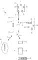
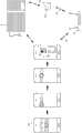
图1为本实用新型的电子装置遥控系统实施例的方块示意图。FIG. 1 is a schematic block diagram of an embodiment of an electronic device remote control system of the present invention.
图2为本实用新型的电子装置遥控系统连接灯控系统实施例的方块示意图。FIG. 2 is a schematic block diagram of an embodiment of an electronic device remote control system connected to a light control system of the present invention.
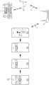
图3为本实用新型的电子装置遥控系统于住家中设置平面示意图。FIG. 3 is a schematic plan view of the installation of the electronic device remote control system of the present invention in a home.
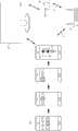
图4为本实用新型系统中手持装置程序遥控音响的实施例操作示意图。Fig. 4 is a schematic diagram of an embodiment of the operation of the handheld device program remote control audio in the system of the present invention.
图5为本实用新型系统中手持装置程序遥控电视的实施例操作示意图。Fig. 5 is a schematic diagram of an embodiment of the operation of the handheld device program remote control TV in the system of the present invention.
图6为本实用新型系统中手持装置程序遥控冷气设备的实施例操作示意图。Fig. 6 is a schematic diagram of an embodiment of the operation of the handheld device program remote control air conditioner in the system of the present invention.
附图标记说明:1电子装置遥控系统;11路由器;12万向遥控信号收发装置;121遥控信号收发器;13无线通讯;14网络分享模块;15手持式装置;151智能型手机;152平板电脑;153遥控器;16云端伺服器;17灯控主机微处理器;18灯控回路;2无线网络;3电子装置。Explanation of reference signs: 1 electronic device remote control system; 11 router; 12 universal remote control signal transceiver; 121 remote control signal transceiver; 13 wireless communication; 14 network sharing module; ; 153 remote controller; 16 cloud server; 17 light control host microprocessor; 18 light control circuit; 2 wireless network; 3 electronic device.
具体实施方式Detailed ways
请参阅图1、3,电子装置遥控系统1包括路由器11,万向遥控信号收发装置12及手持式装置15。路由器11包括网络分享模块14及无线网络连接单元,可通过无线网络2接收手持式装置15的遥控指令。路由器11也可通过内建RF模块等方式,而具备短距离的无线通讯功能,以便将遥控指令发送到至少一个万向遥控信号收发装置12。每一个万向遥控信号收发装置12具有多个指向不同方向的遥控信号收发器121,以便(同参图3)在一个使用空间中可以对需要遥控的多个且/或放在不同方位的电子装置3进行遥控。万向遥控信号收发装置12内建如RF收发器等无线通讯模块,以便与路由器11间以无线通讯13连接,而得以将遥控指令自路由器11传送至万向遥控信号收发装置12,再由遥控信号收发器121发送至所欲遥控的家电等电子装置3。遥控指令乃由手持式装置15控制路由器11发出,再由无线通讯13传输至万向遥控信号收发装置12。手持式装置15可为任何安装有针对电子装置3遥控系统1而开发的遥控应用程序的智能型手机151或平板电脑152等,或是具无线网络连线单元的遥控器153。通过路由器11的网络分享模块14所提供的网络分享单元(即俗称的IP分享功能),可以提供多个手持式装置15同时进行遥控操作。Please refer to FIGS. 1 and 3 , the electronic device
为了可以遥控各种厂牌,规格的各种电子装置3,路由器11具备编辑及学习遥控信号码的单元,以各别学习不同电子装置3的遥控码,并储存于路由器11中。这些学习操作的过程,不必通过额外的电脑主机程序来编辑,而是可通过云端伺服器16来执行该编辑及学习遥控信号码的单元。云端伺服器16乃是通过无线网络2与路由器11连接,所以使用者不需要再额外的安装电脑主机程序来完成遥控码的设定,只要用一般的电脑或手持装置连接至云端伺服器16即可轻松的以内建资料库的型号选择,或是通过学习模式来设定所需遥控电子装置3的遥控码。前述连接路由器11、手持式装置15及云端伺服器16的无线网络为Wi-Fi网络,或其他类似功能的网络。遥控信号收发器121则可为红外线遥控信号收发器,或其他具类似功能的装置。In order to be able to remotely control various
请参阅图2,为了进一步整合使用空间内所有可遥控的设备,以实际达到家庭数字遥控终端装置的功能,电子装置遥控系统1更可包括灯控主机微处理器17,以无线通讯13与路由器11连接,以便通过手持式装置15遥控连接灯控主机微处理器17的至少一灯控回路18。灯控主机微处理器17可以用RJ45等网络线连接分布于室内各处所的4回路、6回路,甚至达8回路的灯控回路18,以组成数字定址灯控系统(DALI Lighting control system)。传统的灯控回路18乃是以网域触控面板来控制。本实用新型通过路由器11与灯控主机微处理器17的连接,让使用者除了可通过手持式装置15,直接在应用程序中以触控方式控制灯控回路18所控制的各灯具(图中未示)的开关、灯光强弱等功能,也可对同一空间中需要遥控的电子装置3(同参图3)如音响、冷气、电视等进行遥控。Please refer to Fig. 2, in order to further integrate all remote-controllable devices in the use space, so as to actually achieve the function of the home digital remote control terminal device, the electronic device
在遥控操作之前,使用者需利用云端伺服器6,及/或直接使用路由器11上的编辑红外线万用码以及红外线学习码的程序,将各别的红外线遥控器,全部学习后储存至路由器11中,并与手持式装置15中应用程序的程序码互相连结,此时手持式装置15即可取代所有的遥控器,而减少了复杂的操作程序,及重复的设备。手持式装置15(如智能型手机151)设定完成时,可采用分享方式,支援多台手持式装置15(如另一支智能型手机151、平板电脑152、遥控器153等)连线设定,达到多机同时遥控的功能。Before the remote control operation, the user needs to use the cloud server 6, and/or directly use the program on the
请参阅图3,为本实用新型的电子装置遥控系统1设置于住家中使用的平面示意图,该路由器11设置于住家客厅或是其他空间中的任意处,而该万向遥控信号收发装置12则设置于各个房间或独立空间中。路由器11与万向遥控信号收发装置12或灯控主机微处理器17(同参图2)之间可以用射频微波通讯,以频宽2.4G赫兹相连接。如此一来,路由器11即可与放置在各房间中的万向遥控信号收发装置12或灯控主机微处理器17进行无线信号的传递。该路由器11包括网络分享模块14及无线网络2连接单元,可通过无线网络2接收遥控指令。而该路由器11也可通过内建RF模块等方式,将遥控指令发送到至设置于各个房间中的万向遥控信号收发装置12。每一个万向遥控信号收发装置12具有多个指向不同方向的遥控信号收发器121,以便在一个使用空间中可以对需要遥控的多个且/或放在不同方位的电子装置3进行遥控。Please refer to FIG. 3 , which is a schematic plan view of the electronic device
配合于各房间设置的万向遥控信号收发装置12,使用者尚可用手持式装置15遥控房中的其他设备,如图4音响的音量及环场特效;如图5电视的选台/大小声/设定功能;如图6冷气的风量/风向/温度;其它如投影机的开关及简报控制;风扇的开关/风量大小……等等,因而可由手持式装置15的遥控操作,即可完成对所处场所的全面性的情境控制。Cooperate with the universal remote
另外,为了方便手持式装置15的遥控操作,也可将图4及图5中所示,将各欲遥控的电子装置3予归类整理,而使用阶层式选单的方式来呈现操作图示,如音响、电视、投影机等可归类在同一电子设备选项之下,使各种遥控设备的操作界面可以有效率的在应用程序中被找到,而加快点选找寻的效率。In addition, in order to facilitate the remote control operation of the
上述的电子装置遥控系统,仅是为了方便举例说明,然而实际施行实并不以此为限,非用以限制本实用新型的专利范围,其电子装置遥控系统仍可随各种应用情况的不同而变更,凡未脱离本实用新型技艺精神所为的等效实施,均应包含于本案的专利范围中。The above-mentioned electronic device remote control system is only for the convenience of illustration. However, the actual implementation is not limited to this, and it is not used to limit the patent scope of the present utility model. The electronic device remote control system can still vary with various applications. And changes, all equivalent implementations that do not deviate from the technical spirit of the present utility model, should be included in the patent scope of this case.
Claims (9)
Translated fromChinesePriority Applications (1)
| Application Number | Priority Date | Filing Date | Title |
|---|---|---|---|
| CN201320519926.2UCN203397498U (en) | 2013-08-23 | 2013-08-23 | Remote control system for electronic device |
Applications Claiming Priority (1)
| Application Number | Priority Date | Filing Date | Title |
|---|---|---|---|
| CN201320519926.2UCN203397498U (en) | 2013-08-23 | 2013-08-23 | Remote control system for electronic device |
Publications (1)
| Publication Number | Publication Date |
|---|---|
| CN203397498Utrue CN203397498U (en) | 2014-01-15 |
Family
ID=49909016
Family Applications (1)
| Application Number | Title | Priority Date | Filing Date |
|---|---|---|---|
| CN201320519926.2UExpired - Fee RelatedCN203397498U (en) | 2013-08-23 | 2013-08-23 | Remote control system for electronic device |
Country Status (1)
| Country | Link |
|---|---|
| CN (1) | CN203397498U (en) |
Cited By (3)
| Publication number | Priority date | Publication date | Assignee | Title |
|---|---|---|---|---|
| CN105046940A (en)* | 2015-07-24 | 2015-11-11 | 青岛海尔科技有限公司 | Control method for infrared remote control household appliance and infrared control host |
| CN106063300A (en)* | 2014-02-17 | 2016-10-26 | 三星电子株式会社 | Display method and mobile device |
| TWI714030B (en)* | 2019-03-21 | 2020-12-21 | 倪文祿 | Electric appliance control device with infrared receiving unit and radio frequency unit |
- 2013
- 2013-08-23CNCN201320519926.2Upatent/CN203397498U/ennot_activeExpired - Fee Related
Cited By (3)
| Publication number | Priority date | Publication date | Assignee | Title |
|---|---|---|---|---|
| CN106063300A (en)* | 2014-02-17 | 2016-10-26 | 三星电子株式会社 | Display method and mobile device |
| CN105046940A (en)* | 2015-07-24 | 2015-11-11 | 青岛海尔科技有限公司 | Control method for infrared remote control household appliance and infrared control host |
| TWI714030B (en)* | 2019-03-21 | 2020-12-21 | 倪文祿 | Electric appliance control device with infrared receiving unit and radio frequency unit |
Similar Documents
| Publication | Publication Date | Title |
|---|---|---|
| CN102854834B (en) | Intelligent switch with long-distance remote control function and long-distance remote control system | |
| CN103546832B (en) | The matching process of home appliance remote controller and system | |
| US9756705B2 (en) | Systems and methods for lighting and appliance control | |
| US20130234534A1 (en) | Power socket with wireless communication capability, system having the same and method thereof | |
| CN203151535U (en) | Intelligent gateway and intelligent household system | |
| TWI488463B (en) | Gateway, smart home system and smart control method of home appliance thereof | |
| US20140180447A1 (en) | Smart adapter and remote control system using the same | |
| US20120295662A1 (en) | Universal Remote | |
| CN103680118A (en) | An intelligent remote control system and a control method thereof | |
| CN104244054A (en) | Remote control method for multiple terminal devices, related devices and system | |
| CN202443574U (en) | System and external equipment for controlling household appliances by means of mobile terminal | |
| CN106155009A (en) | Intelligent home control device and method | |
| CN103970105A (en) | Intelligent home control system and method | |
| CN103442151A (en) | Remote controller and remote control method based on smart mobile terminal | |
| CN103236153A (en) | Infrared switch system, switch control method and infrared repeater | |
| CN106444413A (en) | Smart home control method and device and router | |
| CN205721127U (en) | Smart jack and intelligent home control system | |
| CN203397498U (en) | Remote control system for electronic device | |
| CN102957582A (en) | Remote control system and method for electrical appliances | |
| CN202632512U (en) | Novel system and device for controlling household appliances | |
| CN104217560A (en) | Universal remote control module used in smart phones and its operation method | |
| CN202523209U (en) | Infrared remote control device | |
| CN102087778A (en) | Wireless fidelity (WIFI)-based household appliance control system | |
| WO2013127127A1 (en) | Method, system and external equipment for controlling household appliances by means of mobile terminal | |
| CN104916118A (en) | Method and device for realizing infrared remote control |
Legal Events
| Date | Code | Title | Description |
|---|---|---|---|
| C14 | Grant of patent or utility model | ||
| GR01 | Patent grant | ||
| CF01 | Termination of patent right due to non-payment of annual fee | ||
| CF01 | Termination of patent right due to non-payment of annual fee | Granted publication date:20140115 Termination date:20170823 |