CN203353676U - Atomizer and electronic cigarette - Google Patents
Atomizer and electronic cigaretteDownload PDFInfo
- Publication number
- CN203353676U CN203353676UCN 201320245276CN201320245276UCN203353676UCN 203353676 UCN203353676 UCN 203353676UCN 201320245276CN201320245276CN 201320245276CN 201320245276 UCN201320245276 UCN 201320245276UCN 203353676 UCN203353676 UCN 203353676U
- Authority
- CN
- China
- Prior art keywords
- oil
- sleeve
- atomization
- atomizer
- assembly
- Prior art date
- Legal status (The legal status is an assumption and is not a legal conclusion. Google has not performed a legal analysis and makes no representation as to the accuracy of the status listed.)
- Expired - Lifetime
Links
Images


Landscapes
- Catching Or Destruction (AREA)
Abstract
Translated fromChinese
Description
Translated fromChinese技术领域technical field
本实用新型涉及电子烟产品技术领域,特别涉及一种雾化器及电子烟。The utility model relates to the technical field of electronic cigarette products, in particular to an atomizer and an electronic cigarette.
背景技术Background technique
烟草燃烧的烟雾中存在数十种致癌物质,如焦油等对人体健康会产生非常大的危害,而且,烟雾弥漫在空气中,形成二手烟,周围的人群吸入后也会对身体造成伤害,因此,大多数公共场合都明令禁止吸烟。于是,为满足部分烟民的需要,电子香烟应市而生。There are dozens of carcinogens in the smoke of tobacco burning, such as tar, which will cause great harm to human health. Moreover, the smoke permeates the air and forms second-hand smoke, which will also cause harm to the body after being inhaled by the surrounding people. Therefore , Smoking is banned in most public places. Therefore, in order to meet the needs of some smokers, electronic cigarettes are born in the market.
目前市场上的无棉雾化器烟油的储存多是储存在封闭的容腔内,靠里面的真空吸住烟油,再利用玻纤芯将容腔里的烟油吸收过来,由发热丝加热产生雾化。同时阻油也是靠玻纤芯堵住雾化器的过油孔来实现,因此雾化器的放油和吸油都是靠玻纤芯控制。然而,这种阻油方式较为不可靠,可能在运输或携带的过程中产生漏油现象,使烟油溢出,影响消费体验。At present, most of the smoke oil in the cotton-free atomizer on the market is stored in a closed cavity, and the vacuum inside sucks the smoke oil, and then uses the glass fiber core to absorb the smoke oil in the cavity, and the heating wire Heating produces atomization. At the same time, the oil resistance is also achieved by blocking the oil hole of the atomizer with the glass fiber core, so the oil discharge and oil absorption of the atomizer are controlled by the glass fiber core. However, this oil blocking method is relatively unreliable, and may cause oil leakage during transportation or carrying, causing the e-liquid to overflow and affecting the consumption experience.
实用新型内容Utility model content
本实用新型的主要目的在于,提供一种雾化器及使用该雾化器的电子烟,可有效防止漏油现象,并简化雾化器结构。The main purpose of the utility model is to provide an atomizer and an electronic cigarette using the atomizer, which can effectively prevent oil leakage and simplify the structure of the atomizer.
为实现上述发明目的,本实用新型采用以下技术方案。In order to achieve the above-mentioned purpose of the invention, the utility model adopts the following technical solutions.
本实用新型提供一种雾化器,包括吸嘴、烟弹组件、雾化组件和螺纹套,所述吸嘴、烟弹组件、雾化组件和螺纹套从上到下依次设置于一雾化套的内部,所述烟弹组件包括通气管、套设于通气管上方的上阻油环和套设于通气管下方的下阻油环,所述上阻油环、通气管、下阻油环和雾化套之间形成一个适于容纳烟油的密闭空腔;所述雾化组件设置于烟弹组件的下方,包括固定套、玻纤芯和电极环,所述通气管穿过下阻油环插接于所述固定套,所述玻纤芯夹设于所述固定套与通气管之间,所述电极环插接于所述固定套,并位于螺纹套的中轴线上,所述雾化组件内设置有一密闭的雾化腔,烟油通过一过油孔流入所述雾化腔内,在所述过油孔内设置有一油塞,所述油塞将所述过油孔打开或关闭。The utility model provides an atomizer, which comprises a suction nozzle, a pod assembly, an atomization assembly and a threaded sleeve. The suction nozzle, the pod assembly, the atomization assembly and the threaded sleeve are sequentially arranged in an atomization The inside of the sleeve, the pod assembly includes a vent pipe, an upper oil resistance ring sleeved above the vent pipe and a lower oil resistance ring sleeved below the vent pipe, the upper oil resistance ring, the vent pipe, the lower oil resistance ring A closed cavity suitable for containing e-liquid is formed between the ring and the atomization sleeve; the atomization assembly is arranged under the cartridge assembly, including a fixed sleeve, a glass fiber core and an electrode ring, and the ventilation tube passes through the bottom The oil resistance ring is inserted into the fixed sleeve, the glass fiber core is sandwiched between the fixed sleeve and the vent pipe, the electrode ring is inserted into the fixed sleeve and is located on the central axis of the threaded sleeve, The atomization assembly is provided with a closed atomization chamber, and the smoke oil flows into the atomization chamber through an oil hole, and an oil plug is arranged in the oil hole, and the oil plug connects the oil hole The hole is open or closed.
优选地,所述雾化腔由下阻油环与固定套封闭而成,所述过油孔设置于所述下阻油环上。Preferably, the atomization chamber is closed by a lower oil blocking ring and a fixed sleeve, and the oil passing hole is arranged on the lower oil blocking ring.
优选地,所述油塞包括插入到所述过油孔内的定位部和封堵所述过油孔的遮挡部;所述定位部与一连杆的一端固定连接,所述连杆的另一端延伸到靠近所述螺纹套的下端端部。Preferably, the oil plug includes a positioning portion inserted into the oil hole and a blocking portion to block the oil hole; the positioning portion is fixedly connected to one end of a connecting rod, and the other end of the connecting rod One end extends to the lower end near the threaded sleeve.
优选地,所述连杆与所述螺纹套的中轴线平行,并靠近所述螺纹套的内壁设置。Preferably, the connecting rod is parallel to the central axis of the threaded sleeve and arranged close to the inner wall of the threaded sleeve.
优选地,所述固定套上设置有可供所述连杆穿过的通孔。Preferably, the fixing sleeve is provided with a through hole through which the connecting rod can pass.
优选地,所述螺纹套包括一径向设置的凸缘,所述电极环的上端插接于所述固定套,下端插接于所述凸缘。Preferably, the threaded sleeve includes a radially disposed flange, the upper end of the electrode ring is inserted into the fixing sleeve, and the lower end is inserted into the flange.
优选地,所述固定套包括第一表面,在第一表面上还设置有适于与所述下阻油环配合套接的环形凸台,所述凸台的内径与所述通气管的外径相同或相近,且沿所述凸台的直径方向设置有一用于容置所述玻纤芯的缺口。Preferably, the fixed sleeve includes a first surface, and an annular boss suitable for fitting with the lower oil blocking ring is provided on the first surface, and the inner diameter of the boss is the same as the outer diameter of the ventilation pipe. The diameters are the same or similar, and a gap for accommodating the glass fiber core is provided along the diameter direction of the boss.
优选地,所述缺口延伸至所述第一表面,所述玻纤芯的两端经所述缺口伸入所述雾化腔,中间位于通气管内。Preferably, the notch extends to the first surface, both ends of the glass fiber core extend into the atomization chamber through the notch, and the middle is located in the ventilation pipe.
优选地,所述吸嘴设置有出烟孔,所述出烟孔通过所述通气管和下阻油环与所述雾化腔连通。Preferably, the suction nozzle is provided with a smoke outlet, and the smoke outlet communicates with the atomization chamber through the ventilation pipe and the lower oil resistance ring.
本实用新型还提供一种电子烟,包括电池杆,还包括上述雾化器,所述电池杆包括套杆、电池组件和支承于所述套杆并与电池组件连接的中心针,所述套杆的一端制有可与所述雾化器旋合连接的螺纹,所述套杆与所述雾化器旋合时,所述套杆顶推所述油塞,将所述过油孔打开。The utility model also provides an electronic cigarette, which includes a battery rod and the above-mentioned atomizer. The battery rod includes a sleeve rod, a battery assembly, and a center pin supported on the sleeve rod and connected to the battery assembly. The sleeve One end of the rod is provided with a screw thread that can be screwed with the atomizer. When the sleeve rod is screwed with the atomizer, the sleeve rod pushes the oil plug to open the oil hole .
本实用新型的雾化器及电子烟中,通过下阻油环和固定套封闭一雾化腔,同时,在下阻油环上开设过油孔,并在过油孔中插设油塞,利用油塞的上下移动控制过油孔的开与关的技术方案,可有效防止烟油漏出,不仅消除了消费者的反感情绪,而且结构简单、使用方便。In the atomizer and the electronic cigarette of the present utility model, an atomization chamber is closed by the lower oil blocking ring and the fixed sleeve. The technical scheme of controlling the opening and closing of the oil hole by moving the oil plug up and down can effectively prevent the oil from leaking out, which not only eliminates the resentment of consumers, but also has a simple structure and is easy to use.
附图说明Description of drawings
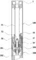
图1是本实用新型实施例一中雾化器的剖视结构示意图。Fig. 1 is a schematic cross-sectional structure diagram of an atomizer in
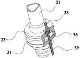
图2是本实用新型实施例一中雾化器的结构分解示意图。Fig. 2 is an exploded schematic diagram of the structure of the atomizer in the first embodiment of the present invention.
图3是本实用新型实施例二中雾化腔的横向剖视结构示意图。Fig. 3 is a schematic cross-sectional structural diagram of the atomization chamber in the second embodiment of the utility model.
图4是本实用新型实施例二中雾化腔的纵向剖视结构示意图。Fig. 4 is a schematic longitudinal sectional view of the atomization chamber in
图5是本实用新型实施例二中油塞的结构示意图。Fig. 5 is a schematic structural view of the oil plug in the second embodiment of the utility model.
图6是本实用新型实施例二中固定套的结构示意图。Fig. 6 is a schematic structural view of the fixing sleeve in the second embodiment of the present invention.
图7是本实用新型实施例三中电子烟的结构示意图。Fig. 7 is a schematic structural diagram of the electronic cigarette in
具体实施方式Detailed ways
以下将结合附图及具体实施例详细说明本实用新型的技术方案,以便更直观地理解本实用新型的发明实质。The technical solution of the utility model will be described in detail below in conjunction with the accompanying drawings and specific embodiments, so as to understand the essence of the utility model more intuitively.
实施例一:Embodiment one:
参照图1和图2所示,本实施例提供一种用于电子烟的雾化器100,包括吸嘴1、烟弹组件2、雾化组件3、螺纹套4和雾化套5,吸嘴1、烟弹组件2、雾化组件3和螺纹套4从上到下依次设置于雾化套5的内部,烟弹组件2包括通气管21、套设于通气管21上方的上阻油环22和套设于通气管21下方的下阻油环23,上阻油环22、通气管21、下阻油环23和雾化套5之间形成一个适于容纳烟油的密闭空腔6。Referring to Figures 1 and 2, this embodiment provides an
雾化组件3设置于烟弹组件2的下方,包括固定套31、玻纤芯32和电极环33,其中,通气管21穿过下阻油环23插接于固定套31,玻纤芯32夹设于固定套31与通气管21之间,其上缠绕有发热丝34,发热丝34用于将烟油加热雾化,其一端与电极环33连接,另一端与螺纹套4连接;电极环33的前端插接于固定套4的中心,后端则通过一绝缘环35插接于螺纹套4内。The
雾化组件3内设置有一密闭的雾化腔36,该雾化腔36通过一过油孔37与上述密闭空腔6连通,在过油孔37内设置有一油塞38,该油塞38可在过油孔37内上下移动,以将过油孔37打开或关闭,过油孔37打开时,烟油进入雾化腔36内,过油孔37关闭时,可阻止烟油进入雾化腔36。A closed
上述吸嘴1和上阻油环22上分别设置有出烟孔11、221,该出烟孔11、221与通气管21、下阻油环23和雾化腔36连通,烟油在雾化腔36内加热雾化后,通过下阻油环23和通气管21进入到吸嘴1,再由人吸入口腔内,实现吸烟效果。The
本实施例的雾化器100在不使用时,油塞38位于过油孔37内,堵住过油孔37,烟油无法进入雾化腔36内,从而不会从电极环33中漏出。When the
在使用时,只需使油塞38向上移动,从而将过油孔37打开,烟油从过油孔37中流入到雾化腔36内,由玻纤芯32吸收后,被缠绕在玻纤芯32上的发热丝34加热雾化,形成烟雾,烟雾在人的抽吸作用下,经通气管21和吸嘴1进入人的口腔内,体验吸烟效果。由此可见,本实用新型结构简单,使用方便,防漏油效果好。When in use, you only need to move the
实施例二:Embodiment two:
参照图3~图6所示,基于实施例一,本实施例中的雾化腔36由下阻油环23与固定套31封闭而成,过油孔37设置于下阻油环23上。油塞38包括用于插入到过油孔37内的定位部381和用于封堵过油孔37的遮挡部382,定位部381还与一连杆39的一端固定连接,该连杆39的另一端延伸到靠近螺纹套5的下端端部,用于控制油塞38上下运动。Referring to FIGS. 3 to 6 , based on the first embodiment, the
较佳地,上述连杆39与螺纹套5的中轴线平行,并靠近螺纹套5的内壁设置,连杆39的长度以其端部位于螺纹套5的开口与电极环33的下端端面之间为宜,使得当油塞38封堵过油孔37时,连杆39的上述端部不会伸出螺纹套5。Preferably, the connecting
同时,固定套31包括第一表面311,在第一表面311上还设置有适于与下阻油环23配合套接的环形凸台312,凸台312的内径与通气管21的外径相同或相近,使凸台312与通气管21能密封配合。沿凸台312的直径方向设置有一用于容置玻纤芯32的缺口313,该缺口313延伸至第一表面311,使得当玻纤芯32被夹持于固定套31与通气管21之间时,玻纤芯32分别支承于第一表面311和通气管21所设置的卡口211(如图2所示)内,且端部经上述缺口313伸入雾化腔36,而中部位于通气管21内。在固定套31上还设置有可供上述连杆39穿过的通孔314,使连杆39穿过该通孔314,并可在通孔314内移动,从而推动油塞38打开或关闭过油孔37。At the same time, the
螺纹套5的内壁具有一径向设置的凸缘(未图示),该凸缘的中心具有一开孔,使电极环33的下端可以与该凸缘插接。The inner wall of the threaded
在使用本实施例的雾化器时,只需将上述连杆39向上顶推,连杆39带动油塞38在过油孔37中向上运动,使遮挡部382离开下阻油环23,过油孔37露出,烟油即可经过油孔37进入雾化腔36中雾化,烟油雾化后经通气管21进入吸嘴1,再通过出烟孔11进入人的口腔内,实现吸食电子烟的效果。When using the atomizer of this embodiment, it is only necessary to push the connecting
实施例三:Embodiment three:
参照图7所示,本实施例提供一种电子烟,该电子烟包括电池杆200,还包括实施例一或二中所述的雾化器100,其中,电池杆200包括套杆201、电池组件202和支承于套杆201并与电池组件202连接的中心针203,套杆201的一端制有螺纹,可通过该螺纹与雾化器100旋合连接。Referring to Fig. 7, this embodiment provides an electronic cigarette, which includes a
当不使用电子烟时,可将电池杆200与雾化器100分开,油塞38位于过油孔37内,将过油孔37堵塞,烟油无法进入雾化腔36,也就不能经玻纤芯32和电极环33的中心孔漏出雾化器100外,从而达到防漏油效果。When not using the electronic cigarette, the
当电池杆200与雾化器100连接时,中心针203在螺纹的旋合力的作用下顶推连杆39,使连杆39向上移动,从而顶推油塞38,使油塞38上移,将过油孔37打开,烟油流入雾化腔36中雾化,雾化后的烟雾经通气管21后进入吸嘴1,消费者可以正常使用电子烟。When the
本实施例的电子烟采用上述雾化器100,具有结构简单,使用方便和防漏油效果好等优点。The electronic cigarette of this embodiment adopts the
综上所述,本实用新型的雾化器及电子烟中,通过下阻油环和固定套封闭一雾化腔,同时,在下阻油环上开设过油孔,并在过油孔中插设油塞,利用油塞的上下移动控制过油孔的开与关的技术方案,可有效防止烟油漏出,不仅消除了消费者的反感情绪,而且结构简单、使用方便。To sum up, in the atomizer and electronic cigarette of the present utility model, an atomization chamber is closed by the lower oil resistance ring and the fixed sleeve, and at the same time, an oil hole is opened on the lower oil resistance ring, and an oil hole is inserted into the oil hole. The oil plug is provided, and the oil plug is used to move up and down to control the opening and closing of the oil hole, which can effectively prevent the oil from leaking out, not only eliminates the disgust of consumers, but also has a simple structure and is easy to use.
以上仅为本说明书为便于理解发明内容所列举的部分实施方式,并非对本实用新型的技术方案进行的任何限定,也非所有可实施方案的穷举,故凡是对本实用新型的形状、结构或构造所做出的任何微小改进或等效替换,均应包含在其保护范围之内。The above are only some of the implementations listed in this specification for the convenience of understanding the content of the invention, and are not any limitation to the technical solutions of the present utility model, nor are they exhaustive of all possible implementations. Therefore, any shape, structure or structure of the utility model Any minor improvement or equivalent replacement made shall be included in its protection scope.
Claims (10)
Translated fromChinesePriority Applications (1)
| Application Number | Priority Date | Filing Date | Title |
|---|---|---|---|
| CN 201320245276CN203353676U (en) | 2013-05-07 | 2013-05-07 | Atomizer and electronic cigarette |
Applications Claiming Priority (1)
| Application Number | Priority Date | Filing Date | Title |
|---|---|---|---|
| CN 201320245276CN203353676U (en) | 2013-05-07 | 2013-05-07 | Atomizer and electronic cigarette |
Publications (1)
| Publication Number | Publication Date |
|---|---|
| CN203353676Utrue CN203353676U (en) | 2013-12-25 |
Family
ID=49801523
Family Applications (1)
| Application Number | Title | Priority Date | Filing Date |
|---|---|---|---|
| CN 201320245276Expired - LifetimeCN203353676U (en) | 2013-05-07 | 2013-05-07 | Atomizer and electronic cigarette |
Country Status (1)
| Country | Link |
|---|---|
| CN (1) | CN203353676U (en) |
Cited By (7)
| Publication number | Priority date | Publication date | Assignee | Title |
|---|---|---|---|---|
| CN104544570A (en)* | 2014-12-31 | 2015-04-29 | 深圳市麦克韦尔科技有限公司 | Inspirator and atomization component thereof |
| CN105707987A (en)* | 2016-05-09 | 2016-06-29 | 周成龙 | Electronic cigarette atomizing device |
| CN105768237A (en)* | 2016-05-09 | 2016-07-20 | 周成龙 | Electronic cigarette atomizer |
| WO2016127390A1 (en)* | 2015-02-13 | 2016-08-18 | 惠州市吉瑞科技有限公司 | Atomisation assembly and electronic cigarette |
| CN106037013A (en)* | 2016-05-24 | 2016-10-26 | 上海绿馨电子科技有限公司 | Ultrasonic oil supply atomizer |
| CN108244710A (en)* | 2018-02-02 | 2018-07-06 | 深圳市劲嘉科技有限公司 | The closed atomizer and its implementation of a kind of electronic cigarette |
| US11470691B2 (en) | 2018-11-19 | 2022-10-11 | Shenzhen Smoore Technology Limited | Atomizing assemblies and electronic atomizing devices having the same |
- 2013
- 2013-05-07CNCN 201320245276patent/CN203353676U/ennot_activeExpired - Lifetime
Cited By (7)
| Publication number | Priority date | Publication date | Assignee | Title |
|---|---|---|---|---|
| CN104544570A (en)* | 2014-12-31 | 2015-04-29 | 深圳市麦克韦尔科技有限公司 | Inspirator and atomization component thereof |
| WO2016127390A1 (en)* | 2015-02-13 | 2016-08-18 | 惠州市吉瑞科技有限公司 | Atomisation assembly and electronic cigarette |
| CN105707987A (en)* | 2016-05-09 | 2016-06-29 | 周成龙 | Electronic cigarette atomizing device |
| CN105768237A (en)* | 2016-05-09 | 2016-07-20 | 周成龙 | Electronic cigarette atomizer |
| CN106037013A (en)* | 2016-05-24 | 2016-10-26 | 上海绿馨电子科技有限公司 | Ultrasonic oil supply atomizer |
| CN108244710A (en)* | 2018-02-02 | 2018-07-06 | 深圳市劲嘉科技有限公司 | The closed atomizer and its implementation of a kind of electronic cigarette |
| US11470691B2 (en) | 2018-11-19 | 2022-10-11 | Shenzhen Smoore Technology Limited | Atomizing assemblies and electronic atomizing devices having the same |
Similar Documents
| Publication | Publication Date | Title |
|---|---|---|
| CN203457802U (en) | Oil-leakage-prevention electronic cigarette atomizer and electronic cigarette | |
| CN203555161U (en) | Atomizer and electronic cigarette provided therewith | |
| CN203353676U (en) | Atomizer and electronic cigarette | |
| CN203851804U (en) | Atomization device of electronic cigarette and electronic cigarette | |
| CN204070562U (en) | Atomizers for electronic cigarettes and electronic cigarettes | |
| US8678012B2 (en) | Tobacco solution atomizing device for electronic cigarette | |
| CN106061298B (en) | Electronic cigarette | |
| CN204070542U (en) | Atomising device and electronic cigarette | |
| CN202456410U (en) | Atomization device of electronic cigarette | |
| CN106028852B (en) | Electronic cigarette and electronic cigarette assemble method | |
| WO2016090648A1 (en) | Electronic cigarette atomizer and electronic cigarette | |
| CN103960780B (en) | Tobacco tar atomising device and electronic cigarette | |
| WO2015144057A1 (en) | Electronic cigarette and tobacco oil bottle thereof | |
| CN104125783B (en) | pod tube | |
| CN203243945U (en) | An electronic cigarette atomizer | |
| KR200460784Y1 (en) | Electronic cigarette | |
| CN204670379U (en) | Atomizer and electronic cigarette | |
| CN106235416B (en) | Atomizer for electronic cigarette and electronic cigarette | |
| KR20130003944U (en) | An atomizer for electronic cigarette | |
| CN105266204A (en) | An environmentally friendly and energy-saving electronic smoke atomizer | |
| CN204245149U (en) | Inhalator and atomizing component thereof | |
| CN204146321U (en) | Atomizer and there is the electronic cigarette of this atomizer | |
| CN204070531U (en) | Nebulizer for electronic cigarette and electronic cigarette | |
| CN105707981A (en) | Atomizer and electronic cigarette | |
| CN207236075U (en) | A kind of electronic smoke atomizer device |
Legal Events
| Date | Code | Title | Description |
|---|---|---|---|
| C14 | Grant of patent or utility model | ||
| GR01 | Patent grant | ||
| CX01 | Expiry of patent term | Granted publication date:20131225 | |
| CX01 | Expiry of patent term |