CN203327952U - Atomizer for electronic cigarette and electronic cigarette - Google Patents
Atomizer for electronic cigarette and electronic cigaretteDownload PDFInfo
- Publication number
- CN203327952U CN203327952UCN2013202998206UCN201320299820UCN203327952UCN 203327952 UCN203327952 UCN 203327952UCN 2013202998206 UCN2013202998206 UCN 2013202998206UCN 201320299820 UCN201320299820 UCN 201320299820UCN 203327952 UCN203327952 UCN 203327952U
- Authority
- CN
- China
- Prior art keywords
- oil
- atomizer
- electronic cigarette
- heating component
- sleeve
- Prior art date
- Legal status (The legal status is an assumption and is not a legal conclusion. Google has not performed a legal analysis and makes no representation as to the accuracy of the status listed.)
- Expired - Lifetime
Links
Images


Landscapes
- Catching Or Destruction (AREA)
Abstract
Translated fromChinese
Description
Translated fromChinese技术领域technical field
本实用新型涉及一种在电子烟领域应用的雾化器,还涉及一种包含该雾化器的和电子烟。The utility model relates to an atomizer used in the field of electronic cigarettes, and also relates to an electronic cigarette including the atomizer.
背景技术Background technique
市场上的电子烟在电池组件上都设置有雾化器,雾化器的雾化套里面设有电子烟用烟弹、使烟油雾化的发热丝组件,所述雾化套的一端连接有金属套。现有技术中,所述雾化套的制作材料一般为金属材料或塑料材料。当所述雾化套采有塑料材料制成时,为克服所述雾化套与所述金属套在固定时存在塑料容易变形导致固定不牢固的问题,现有技术一般会先在所述金属套上打一层固定胶,该固定胶起到粘合固定和防漏油的作用。The electronic cigarettes on the market are all equipped with an atomizer on the battery assembly. The atomization sleeve of the atomizer is equipped with a pod for electronic cigarettes and a heating wire assembly for atomizing the smoke oil. One end of the atomization sleeve is connected to the With metal sleeve. In the prior art, the material for making the atomization sleeve is generally metal or plastic. When the atomization sleeve is made of plastic material, in order to overcome the problem that the plastic is easily deformed and the fixation is not firm when the atomization sleeve and the metal sleeve are fixed, in the prior art, the metal sleeve is generally first Put a layer of fixing glue on the cover, and the fixing glue plays the role of bonding and fixing and preventing oil leakage.
再如申请号为:200810090523.4的发明专利,其公开了一种电子模拟香烟,包括壳体,其特征在于:壳体一端开设进气孔,壳体内安装电源及雾化装置,雾化装置内安装加热器(相当于发热丝组件),电源与加热器连接,壳体内安装胶囊(相当于电子烟用弹),胶囊内装有烟液,胶囊与雾化装置连接,雾化装置的一端安装胶囊穿刺装置,胶囊穿刺装置刺入胶囊内。该公开的现有技术中存在穿刺装置,具有结构复杂的缺点。Another example is the invention patent with the application number: 200810090523.4, which discloses an electronic analog cigarette, including a housing, which is characterized in that: an air inlet is provided at one end of the housing, a power supply and an atomizing device are installed in the housing, and a cigarette is installed in the atomizing device. The heater (equivalent to the heating wire component), the power supply is connected to the heater, the capsule (equivalent to the electronic cigarette bomb) is installed in the shell, the capsule is filled with smoke liquid, the capsule is connected to the atomization device, and one end of the atomization device is installed with a capsule puncture device, the capsule piercing device penetrates into the capsule. The puncturing device in this disclosed prior art has the disadvantage of complex structure.
发明内容Contents of the invention
根据现有技术中所存在的不足,本实用新型的主要目的是提供一种雾化套与金属套连接更牢固的电子烟用雾化器。According to the deficiencies in the prior art, the main purpose of this utility model is to provide an atomizer for electronic cigarettes with a more secure connection between the atomization sleeve and the metal sleeve.
根据现有技术中所存在的不足,本实用新型的另一目的是提供一种结构简单、装配简单的电子烟用雾化器。According to the deficiencies in the prior art, another object of the present invention is to provide an atomizer for electronic cigarette with simple structure and simple assembly.
根据现有技术中所存在的不足,本实用新型还有一目的是提供一种雾化套与金属套连接更牢固的电子烟。According to the deficiencies in the prior art, another purpose of the present invention is to provide an electronic cigarette with a more secure connection between the atomizing sleeve and the metal sleeve.
为达到上述实用新型目的,本实用新型所采用的技术方案是:一种电子烟用雾化器,包括由塑料制成的雾化套、金属套,所述雾化套套接在所述金属套的外表面,所述雾化套的外表面还箍紧有装饰件,所述装饰件和所述金属套设置在所述雾化套的同一端,所述装饰件的设置使所述金属套和所述雾化套紧固连接。In order to achieve the purpose of the above-mentioned utility model, the technical solution adopted by the utility model is: an atomizer for electronic cigarettes, including an atomization sleeve made of plastic and a metal sleeve, and the atomization sleeve is sleeved on the metal sleeve The outer surface of the atomization sleeve is also tightened with a decorative piece, the decorative piece and the metal sleeve are arranged at the same end of the atomization sleeve, and the setting of the decorative piece makes the metal sleeve It is tightly connected with the atomizing sleeve.
本实用新型与现有技术相比,由于本实用新型在所述雾化套的外表面还箍紧有装饰件,这就使得在所述雾化套套接在所述金属套的外表面时,由于所述装饰件可以减小或防止所述雾化套套接在所述金属套的外表面时发生的形变,所以可以使雾化套与金属套连接得更牢固。Compared with the prior art, the utility model has a decorative part tightened on the outer surface of the atomization sleeve, so that when the atomization sleeve is sleeved on the outer surface of the metal sleeve, Since the decorative part can reduce or prevent the deformation of the atomization sleeve when it is fitted on the outer surface of the metal sleeve, the atomization sleeve and the metal sleeve can be connected more firmly.
优选地,本技术方案中所述装饰件由金属材料、玻璃材料或纤维材料制成。Preferably, the decorative part in this technical solution is made of metal material, glass material or fiber material.
进一步地,本技术方案中所述雾化套内还设置有烟弹,所述烟弹包括储油管、所述储油管的两端开口分别设置有密封盖和阻油塞,所述阻油塞上设有通油孔,所述阻油塞的下端连接有发热组件固定座,所述发热组件固定座中设置有发热组件,所述发热组件设在所述通油孔的下方。由于所述阻油塞上设有通油孔,所以相比现有技术而言,不用设置穿刺装置,整体结构变得简单。又由于所述发热组件设在所述通油孔的下方,所以起到阻止所述储油管中的烟油从所述通油孔中漏出的作用。用户在吸烟时,所述发热组件上吸附的烟油被雾化,从而吸附在所述发热组件上的烟油减少,所述发热组件再通过将所述储油管中的烟油吸出,使所述发热组件上的烟油得到补充。由于本实用新型包括了所述发热组件和储油管,而且在使用时不用穿刺装置,所以本实用新型结构简单、装配简单。Further, in the technical solution, the atomization sleeve is also provided with a pod, the pod includes an oil storage tube, and the openings at both ends of the oil storage tube are respectively provided with a sealing cover and an oil blocking plug, and the oil blocking plug An oil through hole is arranged on the top, and the lower end of the oil blocking plug is connected with a heating component fixing seat, and a heating component is arranged in the heating component fixing seat, and the heating component is arranged below the oil through hole. Since the oil blocking plug is provided with an oil through hole, compared with the prior art, no piercing device is required, and the overall structure becomes simple. And because the heating component is arranged below the oil through hole, it plays a role in preventing the smoke oil in the oil storage pipe from leaking out of the oil through hole. When the user smokes, the e-liquid adsorbed on the heating component is atomized, thereby reducing the e-liquid adsorbed on the heating component, and the heating component sucks out the e-liquid in the oil storage tube to make all the e-liquid The e-liquid on the above-mentioned heating components is replenished. Since the utility model includes the heating component and the oil storage pipe, and does not need a puncture device in use, the utility model has a simple structure and is easy to assemble.
进一步地,本技术方案中所述储油空间中不设置储油棉。不设置储油棉可以防止,所述储油棉长时间在烟油中浸泡发生化学反应,影响烟油的雾化口味。Further, no oil storage cotton is provided in the oil storage space in this technical solution. Not setting the oil storage cotton can prevent the chemical reaction of the oil storage cotton soaked in the e-liquid for a long time, which affects the atomization taste of the e-liquid.
进一步地,本技术方案中所述发热组件固定座的底平面上向外延伸出防漏油凸台,所述发热组件处于所述防漏油凸台的上端。所述防漏油凸台的设置目的是,防止在运输或使用过程中,从所述发热组件上溢出的烟油通过所述发热组件固定座上的气流通道流出,发生漏油事故。Further, in this technical solution, an oil leakage prevention boss extends outward from the bottom plane of the heating component fixing seat, and the heating component is located at the upper end of the oil leakage prevention boss. The purpose of the anti-oil leakage boss is to prevent the smoke oil overflowing from the heating component from flowing out through the airflow channel on the fixing seat of the heating component during transportation or use, causing oil leakage accidents.
进一步地,本技术方案中所述发热组件固定座的底平面上向外延伸出两臂,该两臂形成容置空间,所述发热组件处于所述容置空间中。所述容置空间的设置目的是给所述发热组件定位,更好的装配、固定所述发热组件,防止所述发热组件移动。Further, in the technical solution, two arms extend outward from the bottom plane of the heating component fixing seat, and the two arms form an accommodating space, and the heating component is located in the accommodating space. The purpose of setting the accommodating space is to position the heating component, better assemble and fix the heating component, and prevent the heating component from moving.
优选地,本技术方案中所述通油孔的设置个数为至少两个,所述通油孔的总截面积在0.5~2.2mm2。限制所述通油孔的总截面积的目的是,通过控制总截面积的大小,从而来减小漏油事件的发生。Preferably, in the technical solution, the number of the oil through holes is at least two, and the total cross-sectional area of the oil through holes is 0.5-2.2 mm2 . The purpose of limiting the total cross-sectional area of the oil through holes is to reduce the occurrence of oil leakage events by controlling the total cross-sectional area.
优选地,本技术方案中所述密封盖上设有可发生形变的调压膜。所述调压膜的设置目的是,在实际运输过程中,由于两地大气压不一致,可能导致漏油事件;而由于所述调压膜的设置,当所述储油管内的储油空间中气压发生变化时,所述调压膜可以发生形变,给所述储油空间一个缓冲,从而防止漏油事件发生。Preferably, in the technical solution, a deformable pressure regulating film is provided on the sealing cover. The purpose of setting the pressure regulating membrane is that in the actual transportation process, due to the inconsistent atmospheric pressure between the two places, an oil spill may occur; and due to the setting of the pressure regulating membrane, when the air pressure in the oil storage space in the oil storage pipe When the change occurs, the pressure regulating membrane can be deformed to provide a buffer for the oil storage space, thereby preventing oil leakage from happening.
优选地,本技术方案中在所述阻油塞和所述发热组件之间还设置有吸油棉,所述吸油棉设在所述通油孔的正下方,所述吸油棉的上下表面分别与所述阻油塞、所述发热组件接触。所述吸油棉的设置目的是:其一,作为一个密封层,更好地封堵所述通油孔,减小漏油事件的发生;另一个目的是传送烟油,使烟油能均匀地分布在所述发热组件上。Preferably, in this technical solution, an oil-absorbing cotton is also arranged between the oil blocking plug and the heating component, the oil-absorbing cotton is arranged directly below the oil-through hole, and the upper and lower surfaces of the oil-absorbing cotton are respectively connected to the The oil blocking plug is in contact with the heating component. The purpose of setting the oil-absorbing cotton is: first, as a sealing layer, better block the oil hole and reduce the occurrence of oil leakage; the other purpose is to transmit the smoke oil, so that the smoke oil can be evenly distributed Distributed on the heating element.
一种电子烟,包括雾化器和电池组件,所述雾化器包括由塑料制成的雾化套、金属套,所述雾化套套接在所述金属套的外表面,所述雾化套的外表面还箍紧有装饰件,所述装饰件和所述金属套设置在所述雾化套的同一端,所述装饰件的设置使所述金属套和所述雾化套紧固连接。An electronic cigarette, including an atomizer and a battery assembly, the atomizer includes an atomization sleeve made of plastic, and a metal sleeve, the atomization sleeve is sleeved on the outer surface of the metal sleeve, the atomizer The outer surface of the cover is also fastened with a decorative piece, the decorative piece and the metal sleeve are arranged at the same end of the atomization sleeve, and the setting of the decorative piece makes the metal sleeve and the atomization sleeve fastened connect.
本实用新型与现有技术相比,由于本实用新型在所述雾化套的外表面还箍紧有装饰件,这就使得在所述雾化套套接在所述金属套的外表面时,由于所述装饰件可以减小或防止所述雾化套套接在所述金属套的外表面时发生的形变,所以可以使雾化套与金属套连接得更牢固。Compared with the prior art, the utility model has a decorative part tightened on the outer surface of the atomization sleeve, so that when the atomization sleeve is sleeved on the outer surface of the metal sleeve, Since the decorative part can reduce or prevent the deformation of the atomization sleeve when it is fitted on the outer surface of the metal sleeve, the atomization sleeve and the metal sleeve can be connected more firmly.
优选地,本技术方案中所述装饰件由金属材料、玻璃材料或纤维材料制成。Preferably, the decorative part in this technical solution is made of metal material, glass material or fiber material.
进一步地,本技术方案中所述雾化套内还设置有烟弹,所述烟弹包括储油管、所述储油管的两端开口分别设置有密封盖和阻油塞,所述阻油塞上设有通油孔,所述阻油塞的下端连接有发热组件固定座,所述发热组件固定座中设置有发热组件,所述发热组件设在所述通油孔的下方。由于所述阻油塞上设有通油孔,所以相比现有技术而言,不用设置穿刺装置,整体结构变得简单。又由于所述发热组件设在所述通油孔的下方,所以起到阻止所述储油管中的烟油从所述通油孔中漏出的作用。用户在吸烟时,所述发热组件上吸附的烟油被雾化,从而吸附在所述发热组件上的烟油减少,所述发热组件再通过将所述储油管中的烟油吸出,使所述发热组件上的烟油得到补充。由于本实用新型包括了所述发热组件和储油管,而且在使用时不用穿刺装置,所以本实用新型结构简单、装配简单。Further, in the technical solution, the atomization sleeve is also provided with a pod, the pod includes an oil storage tube, and the openings at both ends of the oil storage tube are respectively provided with a sealing cover and an oil blocking plug, and the oil blocking plug An oil through hole is arranged on the top, and the lower end of the oil blocking plug is connected with a heating component fixing seat, and a heating component is arranged in the heating component fixing seat, and the heating component is arranged below the oil through hole. Since the oil blocking plug is provided with an oil through hole, compared with the prior art, no piercing device is required, and the overall structure becomes simple. And because the heating component is arranged below the oil through hole, it plays a role in preventing the smoke oil in the oil storage pipe from leaking out of the oil through hole. When the user smokes, the e-liquid adsorbed on the heating component is atomized, thereby reducing the e-liquid adsorbed on the heating component, and the heating component sucks out the e-liquid in the oil storage tube to make all the e-liquid The e-liquid on the above-mentioned heating components is replenished. Since the utility model includes the heating component and the oil storage pipe, and does not need a puncture device in use, the utility model has a simple structure and is easy to assemble.
进一步地,本技术方案中所述储油空间中不设置储油棉。不设置储油棉可以防止,所述储油棉长时间在烟油中浸泡发生化学反应,影响烟油的雾化口味。Further, no oil storage cotton is provided in the oil storage space in this technical solution. Not setting the oil storage cotton can prevent the chemical reaction of the oil storage cotton soaked in the e-liquid for a long time, which affects the atomization taste of the e-liquid.
进一步地,本技术方案中所述发热组件固定座的底平面上向外延伸出防漏油凸台,所述发热组件处于所述防漏油凸台的上端。所述防漏油凸台的设置目的是,防止在运输或使用过程中,从所述发热组件上溢出的烟油通过所述发热组件固定座上的气流通道流出,发生漏油事故。Further, in this technical solution, an oil leakage prevention boss extends outward from the bottom plane of the heating component fixing seat, and the heating component is located at the upper end of the oil leakage prevention boss. The purpose of the anti-oil leakage boss is to prevent the smoke oil overflowing from the heating component from flowing out through the airflow channel on the fixing seat of the heating component during transportation or use, causing oil leakage accidents.
进一步地,本技术方案中所述发热组件固定座的底平面上向外延伸出两臂,该两臂形成容置空间,所述发热组件处于所述容置空间中。所述容置空间的设置目的是给所述发热组件定位,更好的装配、固定所述发热组件,防止所述发热组件移动。Further, in the technical solution, two arms extend outward from the bottom plane of the heating component fixing seat, and the two arms form an accommodating space, and the heating component is located in the accommodating space. The purpose of setting the accommodating space is to position the heating component, better assemble and fix the heating component, and prevent the heating component from moving.
优选地,本技术方案中所述通油孔的设置个数为至少两个,所述通油孔的总截面积在0.5~2.2mm2。限制所述通油孔的总截面积的目的是,通过控制总截面积的大小,从而来减小漏油事件的发生。Preferably, in the technical solution, the number of the oil through holes is at least two, and the total cross-sectional area of the oil through holes is 0.5-2.2 mm2 . The purpose of limiting the total cross-sectional area of the oil through holes is to reduce the occurrence of oil leakage events by controlling the total cross-sectional area.
优选地,本技术方案中所述密封盖上设有可发生形变的调压膜。所述调压膜的设置目的是,在实际运输过程中,由于两地大气压不一致,可能导致漏油事件;而由于所述调压膜的设置,当所述储油管内的储油空间中气压发生变化时,所述调压膜可以发生形变,给所述储油空间一个缓冲,从而防止漏油事件发生。Preferably, in the technical solution, a deformable pressure regulating film is provided on the sealing cover. The purpose of setting the pressure regulating membrane is that in the actual transportation process, due to the inconsistent atmospheric pressure between the two places, an oil spill may occur; and due to the setting of the pressure regulating membrane, when the air pressure in the oil storage space in the oil storage pipe When the change occurs, the pressure regulating membrane can be deformed to provide a buffer for the oil storage space, thereby preventing oil leakage from happening.
优选地,本技术方案中在所述阻油塞和所述发热组件之间还设置有吸油棉,所述吸油棉设在所述通油孔的正下方,所述吸油棉的上下表面分别与所述阻油塞、所述发热组件接触。所述吸油棉的设置目的是:其一,作为一个密封层,更好地封堵所述通油孔,减小漏油事件的发生;另一个目的是传送烟油,使烟油能均匀地分布在所述发热组件上。Preferably, in this technical solution, an oil-absorbing cotton is also arranged between the oil blocking plug and the heating component, the oil-absorbing cotton is arranged directly below the oil-through hole, and the upper and lower surfaces of the oil-absorbing cotton are respectively connected to the The oil blocking plug is in contact with the heating component. The purpose of setting the oil-absorbing cotton is: first, as a sealing layer, better block the oil hole and reduce the occurrence of oil leakage; the other purpose is to transmit the smoke oil, so that the smoke oil can be evenly distributed Distributed on the heating element.
本实用新型中的其它有益效果,还将在具体实施例中进一步说明。Other beneficial effects of the utility model will be further described in specific embodiments.
附图说明Description of drawings
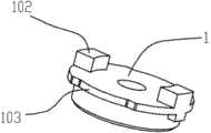
图1为实施例一的外观视图;Fig. 1 is the appearance view of embodiment one;
图2为实施例一的正剖示意图;Fig. 2 is the front sectional schematic diagram of embodiment one;
图3为实施例一中烟弹的正剖视图;Fig. 3 is a front sectional view of the cartridge in Embodiment 1;
图4为实施例二中烟弹的正剖视图;Fig. 4 is a front sectional view of the cartridge in Example 2;
图5为实施例中阻油塞与发热丝组件固定座的连接结构示意图;Fig. 5 is a schematic diagram of the connection structure between the oil blocking plug and the fixing seat of the heating wire assembly in the embodiment;
图6为实施例中阻油塞与发热丝组件的连接结构示意图;Fig. 6 is a schematic diagram of the connection structure between the oil blocking plug and the heating wire assembly in the embodiment;
图7为实施例中发热组件固定座的结构示意图;Fig. 7 is a schematic structural view of the fixing seat of the heating element in the embodiment;
图8为实施例中阻油塞的结构示意图;Fig. 8 is a schematic structural view of the oil blocking plug in the embodiment;
图9为图3中密封盖的结构示意图;Fig. 9 is a schematic structural view of the sealing cover in Fig. 3;
图10为图4中密封盖的结构示意图;Fig. 10 is a schematic structural view of the sealing cover in Fig. 4;
图11为实施例二的正剖示意图。Fig. 11 is a schematic front sectional view of the second embodiment.
附图中各部分结构的标注说明:Notes on the structure of each part in the accompanying drawings:
1-密封盖、101-调压膜、102-纵向定位凸起、103-通气切口、2-储油管、21-储油空间、3-阻油塞、31-漏油孔、4-发热组件、5-发热组件固定座、51-防漏油凸台、52-容置空间、6-吸嘴盖、7-雾化套、8-装饰件、9-金属套。1-sealing cover, 101-pressure regulating membrane, 102-longitudinal positioning protrusion, 103-ventilation cutout, 2-oil storage pipe, 21-oil storage space, 3-oil blocking plug, 31-oil leakage hole, 4-heating component , 5-heating component fixing seat, 51-oil leakage prevention boss, 52-accommodating space, 6-nozzle cover, 7-atomizing sleeve, 8-decorative parts, 9-metal sleeve.
具体实施方式Detailed ways
为了使本实用新型所要解决的技术问题、技术方案及有益效果更加清楚明白,以下结合实施例及附图,对本实用新型进行进一步详细说明。应当理解,此部分所描述的具体实施例仅可用以解释本实用新型,并不用于限定本实用新型。In order to make the technical problems, technical solutions and beneficial effects to be solved by the utility model clearer, the utility model will be further described in detail below in combination with the embodiments and accompanying drawings. It should be understood that the specific embodiments described in this section can only be used to explain the utility model, and are not intended to limit the utility model.
具体实施例一Specific embodiment one
如图1、2所示,本实施例公开了一种电子烟用雾化器,包括由塑料制成的雾化套7、金属套9,所述雾化套7套接在所述金属套9的外表面,所述雾化套7的外表面还箍紧有装饰件8,所述装饰件8和所述金属套9设置在所述雾化套7的同一端,所述装饰件8的设置使所述金属套9和所述雾化套7紧固连接。As shown in Figures 1 and 2, this embodiment discloses an atomizer for electronic cigarettes, which includes an
优选地,在本实施例中所述装饰件8为金属材料制成。事实上本领域人员应该知道,所述装饰件8还可以由玻璃材料、塑料材料或纤维材料制成,所述装饰件8采用玻璃材料、塑料材料或纤维材料制造时,在达到本实用新型的发明目的条件下,应等同在本实用新型的保护范围内。Preferably, the
优选地,如图3所示,所述雾化套7内还设置有烟弹,所述烟弹包括储油管2、所述储油管2的两端开口分别设置有密封盖1和阻油塞3,所述阻油塞3上设有通油孔31(在此需补充说明的是,所述通油孔31可以设置成孔,也可以设置成切口等其它形式。),所述阻油塞3的下端连接有发热组件固定座5,所述发热组件固定座5中设置有发热组件4,所述发热组件4设在所述通油孔31的下方。实际上,所述储油管2也可以设置成一端开口的形式,即:所述储油管2与所述密封盖1设置成一体结构。这种设置方式在本发明的基础上,本领域技术人员不需要付出创造性性的劳动就可以获知,理同应属于本发明创造的保护范围内。所述雾化套7的另一端设有吸嘴盖6,所述吸嘴盖6压在所述密封盖1上。Preferably, as shown in FIG. 3 , the
为进一步阐述本实施例,再如图3所示,所述储油空间4中不设置储油棉。To further illustrate this embodiment, as shown in FIG. 3 , no oil storage cotton is provided in the
如图5、图7所示,所述发热组件固定座5的底平面上向外延伸出防漏油凸台51,所述发热组件4处于所述防漏油凸台51的上端。如图4所示,在本实施例中,所述防漏油凸台51支撑着所述发热组件4,使所述发热组件4离开所述发热组件固定座5的底平面。As shown in FIG. 5 and FIG. 7 , an oil
如图6所示,所述发热组件固定座5的底平面上向外延伸出两臂,该两臂形成容置空间52,所述发热组件4处于所述容置空间52中。As shown in FIG. 6 , two arms extend outward from the bottom plane of the heating component fixing seat 5 , and the two arms form an
如图5、图8所示,在本实施例中,所述通油孔31的设置个数为两个,所述通油孔31的总截面积在0.5~2.2mm2。在保证所述通油孔31的总截面积在0.5~2.2mm2的条件下,所述通油孔31的设置个数还可以是两个以上。As shown in FIG. 5 and FIG. 8 , in this embodiment, the number of the oil passage holes 31 is two, and the total cross-sectional area of the oil passage holes 31 is 0.5-2.2 mm2 . Under the condition that the total cross-sectional area of the oil passage holes 31 is 0.5-2.2 mm2 , the number of the oil passage holes 31 can be more than two.
如图9所示,所述密封盖1上设有纵向定位凸起102和通气切口103。所述纵向定位凸起102的设置目的是,在本实用新型安装至电子烟用雾化器内后,如图9所示,吸嘴盖6可以压在所述纵向定位凸起102上,使整个烟弹不在雾化器内移动。As shown in FIG. 9 , the sealing cover 1 is provided with a
优选地,在所述阻油塞3和所述发热组件4之间还设置有吸油棉,所述吸油棉设在所述通油孔31的正下方,所述吸油棉的上下表面分别与所述阻油塞3、所述发热组件4接触。Preferably, an oil-absorbing cotton is also arranged between the
具体实施例二Specific embodiment two
如图4、图10、图11所示,本实施例与实施例一的主要区别在于:所述密封盖1上设有可发生形变的调压膜101。在本实施例中,所述调压膜101与所述密封盖1为一体成形结构。实际上,所述调压膜101和所述密封盖1还可以设置成分体结构,然后通过固定连接形成一体。As shown in FIG. 4 , FIG. 10 , and FIG. 11 , the main difference between this embodiment and Embodiment 1 is that a deformable pressure-regulating
在本优选实施例中,所述密封盖1由软材料制成。该软材料可选用硅胶、橡胶等。In this preferred embodiment, the sealing cover 1 is made of soft material. The soft material can be selected from silica gel, rubber and the like.
具体实施例三Specific embodiment three
一种电子烟,包括电池组件和雾化器,该雾化器为实施例一中所描述的雾化器。An electronic cigarette includes a battery assembly and an atomizer, and the atomizer is the atomizer described in Embodiment 1.
具体实施例四Specific embodiment four
一种电子烟,包括电池组件和雾化器,该雾化器为实施例二中所描述的雾化器。An electronic cigarette includes a battery assembly and an atomizer, and the atomizer is the atomizer described in
Claims (11)
Translated fromChinesePriority Applications (1)
| Application Number | Priority Date | Filing Date | Title |
|---|---|---|---|
| CN2013202998206UCN203327952U (en) | 2013-05-29 | 2013-05-29 | Atomizer for electronic cigarette and electronic cigarette |
Applications Claiming Priority (1)
| Application Number | Priority Date | Filing Date | Title |
|---|---|---|---|
| CN2013202998206UCN203327952U (en) | 2013-05-29 | 2013-05-29 | Atomizer for electronic cigarette and electronic cigarette |
Publications (1)
| Publication Number | Publication Date |
|---|---|
| CN203327952Utrue CN203327952U (en) | 2013-12-11 |
Family
ID=49696670
Family Applications (1)
| Application Number | Title | Priority Date | Filing Date |
|---|---|---|---|
| CN2013202998206UExpired - LifetimeCN203327952U (en) | 2013-05-29 | 2013-05-29 | Atomizer for electronic cigarette and electronic cigarette |
Country Status (1)
| Country | Link |
|---|---|
| CN (1) | CN203327952U (en) |
Cited By (6)
| Publication number | Priority date | Publication date | Assignee | Title |
|---|---|---|---|---|
| CN103263085A (en)* | 2013-05-29 | 2013-08-28 | 深圳市合元科技有限公司 | Atomizer for electronic cigarette and electronic cigarette |
| CN104720116A (en)* | 2015-01-30 | 2015-06-24 | 林光榕 | Electronic cigarette atomizer |
| CN106072771A (en)* | 2016-07-20 | 2016-11-09 | 卓尔悦欧洲控股有限公司 | Leakproof liquid smoke bullet and atomising device thereof |
| CN106714593A (en)* | 2014-09-19 | 2017-05-24 | 惠州市吉瑞科技有限公司 | Vaporization assembly and electronic cigarette |
| CN107072299A (en)* | 2014-06-05 | 2017-08-18 | 吉瑞高新科技股份有限公司 | Electronic cigarette and electronic cigarette assemble method |
| WO2017166334A1 (en)* | 2016-03-28 | 2017-10-05 | 梅小建 | Electronic cigarette atomizer and e-liquid barrier device thereof |
- 2013
- 2013-05-29CNCN2013202998206Upatent/CN203327952U/ennot_activeExpired - Lifetime
Cited By (8)
| Publication number | Priority date | Publication date | Assignee | Title |
|---|---|---|---|---|
| CN103263085A (en)* | 2013-05-29 | 2013-08-28 | 深圳市合元科技有限公司 | Atomizer for electronic cigarette and electronic cigarette |
| CN103263085B (en)* | 2013-05-29 | 2017-02-22 | 深圳市合元科技有限公司 | Atomizer for electronic cigarette and electronic cigarette |
| CN107072299A (en)* | 2014-06-05 | 2017-08-18 | 吉瑞高新科技股份有限公司 | Electronic cigarette and electronic cigarette assemble method |
| CN106714593A (en)* | 2014-09-19 | 2017-05-24 | 惠州市吉瑞科技有限公司 | Vaporization assembly and electronic cigarette |
| CN104720116A (en)* | 2015-01-30 | 2015-06-24 | 林光榕 | Electronic cigarette atomizer |
| CN104720116B (en)* | 2015-01-30 | 2018-03-06 | 林光榕 | Electronic smoke atomizer |
| WO2017166334A1 (en)* | 2016-03-28 | 2017-10-05 | 梅小建 | Electronic cigarette atomizer and e-liquid barrier device thereof |
| CN106072771A (en)* | 2016-07-20 | 2016-11-09 | 卓尔悦欧洲控股有限公司 | Leakproof liquid smoke bullet and atomising device thereof |
Similar Documents
| Publication | Publication Date | Title |
|---|---|---|
| CN103263085B (en) | Atomizer for electronic cigarette and electronic cigarette | |
| CN203327952U (en) | Atomizer for electronic cigarette and electronic cigarette | |
| CN203353675U (en) | Cigarette cartridge for electronic cigarette, atomizer comprising cigarette cartridge, and electronic cigarette | |
| US10966457B2 (en) | Atomizing head, atomizer and electronic cigarette thereof | |
| US20170156402A1 (en) | Atomizer and electronic cigarette comprising same | |
| CN208692316U (en) | A kind of novel electronic cigarette atomizer | |
| CN216701658U (en) | Atomizer and aerosol generating device | |
| WO2012152053A1 (en) | Atomization nozzle of electronic atomization inhaler | |
| WO2018130023A1 (en) | Electronic cigarette atomizer | |
| CN211129739U (en) | A leak-proof electronic cigarette | |
| WO2017210969A1 (en) | Electronic cigarette | |
| WO2015117285A1 (en) | Atomizer | |
| CN206043435U (en) | Nebulizer and the electronic cigarette including the nebulizer | |
| CN103960780B (en) | Tobacco tar atomising device and electronic cigarette | |
| JP2015519903A (en) | Electronic cigarette and electronic cigarette suction device | |
| CN106418709B (en) | Electronic cigarette with transverse liquid supply | |
| CN206433760U (en) | A kind of electronic cigarette atomizing cotton component, oil guide structure and atomizer | |
| CN106136327A (en) | Electronic cigarette and its atomizer | |
| CN112450494B (en) | Nebulizer holder, nebulizer assembly and nebulizer | |
| CN220109122U (en) | Atomizer and electronic atomization device | |
| CN212971655U (en) | Ultrasonic atomizer and electronic cigarette | |
| CN206978764U (en) | A kind of electronic smoke atomizer | |
| CN217771471U (en) | Atomizing core component for electronic cigarette, cartridge for electronic cigarette and electronic cigarette | |
| CN206197014U (en) | Electronic smoking set | |
| CN217446677U (en) | Atomizer and electronic atomization device |
Legal Events
| Date | Code | Title | Description |
|---|---|---|---|
| C14 | Grant of patent or utility model | ||
| GR01 | Patent grant |