CN203313289U - camera lens structure - Google Patents
camera lens structureDownload PDFInfo
- Publication number
- CN203313289U CN203313289UCN2013203482933UCN201320348293UCN203313289UCN 203313289 UCN203313289 UCN 203313289UCN 2013203482933 UCN2013203482933 UCN 2013203482933UCN 201320348293 UCN201320348293 UCN 201320348293UCN 203313289 UCN203313289 UCN 203313289U
- Authority
- CN
- China
- Prior art keywords
- lens
- base
- camera lens
- camera
- lens structure
- Prior art date
- Legal status (The legal status is an assumption and is not a legal conclusion. Google has not performed a legal analysis and makes no representation as to the accuracy of the status listed.)
- Expired - Fee Related
Links
- 239000000463materialSubstances0.000claimsabstractdescription25
- 238000000034methodMethods0.000claimsabstractdescription16
- 239000012790adhesive layerSubstances0.000claimsdescription5
- 239000011521glassSubstances0.000claimsdescription5
- 238000010295mobile communicationMethods0.000claimsdescription4
- 230000007246mechanismEffects0.000claimsdescription3
- NIXOWILDQLNWCW-UHFFFAOYSA-Nacrylic acid groupChemical groupC(C=C)(=O)ONIXOWILDQLNWCW-UHFFFAOYSA-N0.000claimsdescription2
- 230000004927fusionEffects0.000claims1
- 238000004080punchingMethods0.000claims1
- 239000012780transparent materialSubstances0.000claims1
- 238000012545processingMethods0.000abstractdescription16
- 238000004891communicationMethods0.000abstractdescription5
- 230000008520organizationEffects0.000abstract1
- 238000013461designMethods0.000description10
- 238000004519manufacturing processMethods0.000description10
- 238000007639printingMethods0.000description7
- 239000003086colorantSubstances0.000description6
- 230000008569processEffects0.000description5
- 230000000007visual effectEffects0.000description4
- 230000005540biological transmissionEffects0.000description3
- 239000000853adhesiveSubstances0.000description2
- 230000001070adhesive effectEffects0.000description2
- 230000000903blocking effectEffects0.000description2
- 239000000428dustSubstances0.000description2
- 238000000227grindingMethods0.000description2
- 238000001746injection mouldingMethods0.000description2
- 239000010410layerSubstances0.000description2
- 238000002844meltingMethods0.000description2
- 230000008018meltingEffects0.000description2
- 230000009467reductionEffects0.000description2
- 239000000243solutionSubstances0.000description2
- 238000001179sorption measurementMethods0.000description2
- 238000004381surface treatmentMethods0.000description2
- 239000002699waste materialSubstances0.000description2
- 208000027418Wounds and injuryDiseases0.000description1
- 239000011248coating agentSubstances0.000description1
- 238000000576coating methodMethods0.000description1
- 230000006378damageEffects0.000description1
- 238000011161developmentMethods0.000description1
- 230000000694effectsEffects0.000description1
- 238000009713electroplatingMethods0.000description1
- 238000005516engineering processMethods0.000description1
- 239000012943hotmeltSubstances0.000description1
- 208000014674injuryDiseases0.000description1
- 238000004377microelectronicMethods0.000description1
- 238000012986modificationMethods0.000description1
- 230000004048modificationEffects0.000description1
- 238000007649pad printingMethods0.000description1
- 230000001681protective effectEffects0.000description1
- 238000006748scratchingMethods0.000description1
- 230000002393scratching effectEffects0.000description1
- 238000007592spray painting techniqueMethods0.000description1
- 238000005496temperingMethods0.000description1
- -1ultrasonicSubstances0.000description1
Images


Landscapes
- Eyeglasses (AREA)
Abstract
Description
Translated fromChinese技术领域technical field
本实用新型涉及一种镜片结构;尤其是指一种应用于摄像头的镜片结构,可应用于各种手持装置,如:手机、平板电脑等各式手持通讯装置之中。The utility model relates to a lens structure; in particular, it refers to a lens structure applied to a camera, which can be applied to various handheld devices, such as mobile phones, tablet computers and other handheld communication devices.
背景技术Background technique
随着多媒体技术的发展,数位相机及摄影机越来越为广大消费者青睐,人们对数位摄影装置愈来愈追求其小型化,同时由于携带式电子装置的轻薄短小、携带方便,人们希望于能够于携带式电子装置上实现撷取物体影像的功能,且获得清晰画面,由此具摄像头的携带式电子装置应运而生。With the development of multimedia technology, digital cameras and video cameras are becoming more and more popular among consumers. People are increasingly pursuing the miniaturization of digital photography devices. Realize the function of capturing object images on the portable electronic device, and obtain a clear picture, thus the portable electronic device with camera emerges as the times require.
目前携带式的手持装置,如手机及平板电脑等,大都具有通讯功能(如:3G功能或是WIFI连线等)及摄影功能来提升使用的便利性及趣味性,摄像头一般都安装于手持通讯装置的外壳上,以利于使用者拍摄;而摄像头外部皆设置有保护镜片,以防止摄像头受外在因素影响而损坏,制作摄像头的镜片,若以玻璃材质举例,在加工程序上必须经过:切割、仿型、倒边、钢化、平磨、印刷及镀膜等程序,才能达到保护摄像头及透光性等基本使用的要求,由于玻璃材质坚硬,所以会大幅影响加工的速度,增加制作的工时,而且在仿型及倒边的研磨过程中,若是发生镜片崩边的情况,将可能使玻璃材料作废报销。Most of the current portable handheld devices, such as mobile phones and tablet computers, have communication functions (such as: 3G function or WIFI connection, etc.) and photography functions to improve the convenience and fun of use. Cameras are generally installed in handheld communication On the outer shell of the device, it is convenient for the user to take pictures; and the camera is equipped with a protective lens to prevent the camera from being damaged by external factors. To make the lens of the camera, if the glass material is used as an example, the processing procedure must go through: cutting , profiling, chamfering, tempering, flat grinding, printing and coating, etc., in order to meet the basic requirements of camera protection and light transmission. Because the glass material is hard, it will greatly affect the processing speed and increase the production time. Moreover, in the grinding process of profiling and edge chamfering, if the edge chipping of the lens occurs, the glass material may be scrapped and reimbursed.
同时目前摄像头镜片的尺寸都非常微小,所以许多的加工步骤必须以人工方式逐片来操作(如倒边等),非常浪费人力且生产效率低,但摄像头在微电子的日益创新下,已经发展到非常微小的尺寸,其实摄像头镜片仅需让摄像头部分可透光即可达成拍摄目的,并不需让全部的镜片区域透光,所以目前的镜片需另外以印刷程序来覆盖大部分的镜片面积(仅留下透光窗口),如此作法亦非常浪费镜片材料,故如何改善前述现有镜片生产加工上的缺点,进而提高生产速度及良率,实为一具实用价值的技术课题。At the same time, the size of the current camera lens is very small, so many processing steps must be manually operated one by one (such as beveling, etc.), which is a waste of manpower and low production efficiency. However, the camera has developed under the increasing innovation of microelectronics. To a very small size, in fact, the camera lens only needs to allow the camera part to transmit light to achieve the purpose of shooting, and does not need to allow the entire lens area to transmit light, so the current lens needs to be printed to cover most of the lens area. (Leaving only the light-transmitting window), this method is also a waste of lens material, so how to improve the above-mentioned shortcomings in the production and processing of existing lenses, and then improve the production speed and yield, is actually a technical issue with practical value.
有鉴于此,本设计人针对上述摄像头镜片结构设计上未臻完善所导致的诸多缺失及不便,而深入构思,且积极研究改良试做而开发设计出本案。In view of this, the designer aimed at the many shortcomings and inconveniences caused by the imperfect structure design of the above-mentioned camera lens, and deeply conceived, and actively researched and improved the trial production to develop and design this case.
实用新型内容Utility model content
本实用新型的目的在于提供一种摄像头镜片结构,可有效减少透镜材料的使用,进而简化摄像头镜片的加工程序,并提升良率进而增加产能,同时此种设计结构可于使用时减少镜片的刮伤,来保护镜片提高使用寿命。The purpose of this utility model is to provide a camera lens structure, which can effectively reduce the use of lens materials, further simplify the processing procedure of the camera lens, improve the yield rate and increase production capacity, and at the same time, this design structure can reduce lens scratches during use. Injury, to protect the lens to improve the service life.
为了达成上述目的,本实用新型的解决方案是:In order to achieve the above object, the solution of the present utility model is:
一种摄像头镜片结构,该摄像头镜片结构设置于一行动通讯装置的表缘并用以保护摄像头,该摄像头镜片结构包括:A camera lens structure, the camera lens structure is arranged on the surface edge of a mobile communication device and used to protect the camera, the camera lens structure includes:
一基座,该基座中设置有一容置槽,该容置槽顶缘还设置有一通光孔;及一透镜,该透镜设置于该容置槽中并叠合于该通光孔之下以与该基座结合为一体。A base, the base is provided with an accommodating groove, the top edge of the accommodating groove is also provided with a light through hole; and a lens, the lens is arranged in the accommodating groove and superimposed under the light through hole to integrate with the base.
上述通光孔周缘还设置有至少一档片,该档片用以顶峙该透镜,以防该透镜脱落出该通光孔。There is also at least one blocking piece on the periphery of the above-mentioned light-through hole, and the blocking piece is used to support the lens to prevent the lens from falling out of the light-through hole.
上述基座上缘还设置有至少一凸肋。The upper edge of the base is also provided with at least one rib.
上述透镜为一玻璃材质、一压克力材质及一透光材质中任选其一制成。The above-mentioned lens is made of a glass material, an acrylic material, and a light-transmitting material.
上述基座还以一热熔、一超音波、一黏合、一冲压及一机构嵌合方式中任选其一,以将该透镜固定于该容置槽中。The above-mentioned base also selects one of hot-melt, ultrasonic, adhesive, stamping and mechanical fitting to fix the lens in the accommodating groove.
上述基座背缘还设置有一黏合层。An adhesive layer is also provided on the back edge of the above-mentioned base.
采用上述结构后,本实用新型摄像头镜片结构,将基座结合透镜的设计,可有效简化现有整面镜片的繁琐加工生产流程及降低材料成本,其中基座可选用易于生产(射出成型)的材质来制作,可让基座更易于装配于行动通讯装置的上且有良好的贴合度,基座更可选用多样化的颜色,或是易于印刷上色的材质,来突破现有架构在镜片上印刷的限制,使摄像头镜片能创造出更多元化的视觉效果,容置槽的设计可容许透镜尺寸上较大的误差,并省略仿型及倒边的加工程序,降低崩边来提高良率,且透镜材质的减少可降低成本外,更可减少组装时静电灰尘吸附的机率;且本实用新型可借由基座通光孔与透镜的结合,即可达成摄像头透光窗口的拍摄功能,且借由基座与透镜结合后的高低差,可于使用时减少透镜的刮伤,进而保护透镜提高使用寿命。 After adopting the above-mentioned structure, the camera lens structure of the present invention combines the design of the base with the lens, which can effectively simplify the tedious processing and production process of the existing entire lens and reduce the cost of materials, wherein the base can be selected to be easily produced (injection molding). The base is made of different materials, which can make the base easier to assemble on the mobile communication device and has a good fit. The base can also be selected from a variety of colors, or materials that are easy to print and color, to break through the existing structure. The limitation of printing on the lens enables the camera lens to create more diversified visual effects. The design of the accommodating groove can allow large errors in lens size, and omit the processing procedures of profiling and chamfering to reduce the risk of edge collapse. Improve the yield rate, and the reduction of the lens material can reduce the cost, and can also reduce the probability of electrostatic dust adsorption during assembly; and the utility model can achieve the light-transmitting window of the camera through the combination of the light-through hole of the base and the lens. The shooting function, and the height difference between the base and the lens can reduce the scratches of the lens during use, thereby protecting the lens and improving the service life. the
附图说明Description of drawings
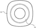
图1是本实用新型摄像头镜片结构的第一实施例立体图;Fig. 1 is the perspective view of the first embodiment of the camera lens structure of the present invention;
图2A是本实用新型摄像头镜片结构的第一实施例正视图;Fig. 2A is the front view of the first embodiment of the camera lens structure of the present invention;
图2B是本实用新型摄像头镜片结构的第一实施例背视图;Fig. 2B is the back view of the first embodiment of the camera lens structure of the present invention;
图3是本实用新型摄像头镜片结构的第一实施例剖视图;Fig. 3 is a sectional view of the first embodiment of the camera lens structure of the present invention;
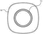
图4是本实用新型摄像头镜片结构的第二实施例立体图;4 is a perspective view of a second embodiment of the camera lens structure of the present invention;
图5A是本实用新型摄像头镜片结构的第二实施例正视图;Fig. 5A is the front view of the second embodiment of the camera lens structure of the present invention;
图5B是本实用新型摄像头镜片结构的第二实施例背视图;Fig. 5B is a back view of the second embodiment of the camera lens structure of the present invention;
图6是本实用新型摄像头镜片结构的第二实施例剖视图。Fig. 6 is a cross-sectional view of the second embodiment of the camera lens structure of the present invention.
符号说明Symbol Description
10基座 11档片 12凸肋 20透镜 30黏合层。10
具体实施方式Detailed ways
为了进一步解释本实用新型的技术方案,下面通过具体实施例来对本实用新型进行详细阐述。In order to further explain the technical solution of the utility model, the utility model is described in detail through specific examples below.
请先参照图1,是本实用新型摄像头镜片结构的第一实施例立体图。Please refer to FIG. 1 first, which is a perspective view of the first embodiment of the camera lens structure of the present invention.
本实用新型摄像头镜片结构主要包含有基座10及透镜20两个单元组成,其中基座10中设置有一容置槽,恰可用于容置此透镜20,而基座10的容置槽顶缘设置有一通光孔,可用以透光作为摄像头窗口,基座10材质的原色可选用不同的颜色来制作,甚至基座10本体亦可利用特殊工法,来制作出立体凹凸的浮雕型态,或是同心螺旋纹等不同的造型设计,以增添视觉感官的丰富性,又或是将基座10正面作不同式样的表面处理,如:印刷、喷漆、移印、丝印或电镀等各种方式,来形成各种不同颜色、式样花色,来提供使用者有多样化的外观选择,生产时亦可于前述表面处理完成后再加印文字及数字(如:品牌、型号及像素)等,来达到显示讯息的特殊目的。The camera lens structure of the utility model mainly includes two units of a
接下来请继续参照图2A是本实用新型摄像头镜片结构的第一实施例正视图;本实用新型以正面观之时,与现有的摄像头镜片近似,但结构则全然不同于单片式结构的现有摄像头镜片,本实用新型以基座10来取代现有摄像头镜片上的印刷层,使加工上更为简易且外观富有多变化;从背视图可以看出,通光孔的周缘设置有至少一片的档片11,此档片11可用来顶峙住透镜20,以防止透镜20掉落出基座10之外,前述结构可参照图2B是本实用新型摄像头镜片结构的第一实施例背视图。Next, please continue to refer to FIG. 2A, which is a front view of the first embodiment of the camera lens structure of the present invention; when the utility model is viewed from the front, it is similar to the existing camera lens, but its structure is completely different from that of the monolithic structure. The existing camera lens, the utility model replaces the printing layer on the existing camera lens with the
最后请参照图3是本实用新型摄像头镜片结构的第一实施例剖视图,从图中可以看出透镜20经档片11顶峙住后,会与基座10表面形成微幅的高低差距,由于透镜20会略为内缩于基座10之内,如此则可有效降低刮伤透镜20的机会,同时由基座10与透镜20的尺寸比例可以看出,本实用新型的结构可大幅减少使用透镜20材质(不似现有的摄像头镜片采用整片透镜材质来加工制作),可有效降低透镜20成本及加工费用的支出(例如:可省却仿型及倒边的程序,减少透镜加工时产生崩边的机会),透镜20设置于容置槽后,可进一步运用热熔、超音波、黏合、冲压或是设计机构嵌合方式,来将透镜20固定于容置槽内,而基座10背缘则可设置有黏合层30,以利于摄像头镜片结构成品与手持通讯装置的黏合装配程序。Finally, please refer to Fig. 3, which is a sectional view of the first embodiment of the camera lens structure of the present invention. It can be seen from the figure that after the
在不违反同一创作精神之下,本实用新型更可有以下实施状态,请继续参照图4,是本实用新型摄像头镜片结构的第二实施例立体图;此一实施状态的摄像头镜片结构主要包含有基座10及透镜20两个单元组成,其中基座10表缘设置有至少一凸肋12,而基座10中则设置有容置槽,恰可用于容置此透镜20,而基座10的容置槽顶缘上设置有一通光孔,可用以透光作为摄像头窗口,基座10材质的原色可选用不同的颜色来制作,以增添视觉感官的丰富性,或是将基座10正面作不同式样的印刷处理(如颜色、式样),来提供使用者有多样化的外观选择。Without violating the same creative spirit, the utility model can have the following implementation states, please continue to refer to Figure 4, which is a perspective view of the second embodiment of the camera lens structure of the utility model; the camera lens structure in this implementation state mainly includes The
接下来请继续参照图5A是本实用新型摄像头镜片结构的第二实施例正视图;本实用新型以正面观之时,可以看出本实用新型以基座10取代现有摄像头镜片上的印刷层,使加工更为简易,基座10正面上设置有凸肋12更可对透镜产生保护效用,并增加整体视觉的立体感;从背视图可以看出,通光孔的周缘设置有至少一片的档片11,此档片11可用来顶峙住透镜20,以防止透镜20掉落出基座10之外,前述结构可参照图5B是本实用新型摄像头镜片结构的第二实施例背视图。Next, please continue to refer to FIG. 5A, which is a front view of the second embodiment of the camera lens structure of the present invention; when the utility model is viewed from the front, it can be seen that the utility model replaces the printing layer on the existing camera lens with a
最后请参照图6是本实用新型摄像头镜片结构的第二实施例剖视图,从图中可以看出透镜20经档片11顶峙住后,会与基座10表面形成微幅的高低差,加上基座10表缘的凸肋12将会使透镜20内缩于基座10之内,如此则可有效防止透镜20被刮伤的机会,同时由基座10与透镜20的尺寸比例可以看出,本实用新型的结构将可大幅减少使用透镜20材质(不似现有的摄像头镜片采用整片透镜材质来加工制作),可有效降低透镜20成本及加工费用的支出(例如:可省却仿型及倒边的程序,减少透镜加工时产生崩边的机会),透镜20设置于容置槽后,可进一步运用热熔、超音波、黏合、冲压或是设计机构嵌合方式,来将透镜20固定于容置槽内,而基座10背缘则可设置有黏合层30,以利于成品的黏合装配程序。Finally, please refer to FIG. 6, which is a cross-sectional view of the second embodiment of the lens structure of the camera lens of the present invention. It can be seen from the figure that after the
由前述说明可了解本实用新型摄像头镜片结构,将基座结合透镜的设计,可有效简化现有整面镜片的繁琐加工生产流程及降低材料成本,其中基座可选用易于生产(射出成型)的材质来制作,可让基座更易于装配于行动通讯装置的上且有良好的贴合度,基座更可选用多样化的颜色,或是易于印刷上色的材质,来突破现有架构在镜片上印刷的限制,使摄像头镜片能创造出更多元化的视觉效果,容置槽的设计可容许透镜尺寸上较大的误差,并省略仿型及倒边的加工程序,降低崩边来提高良率,且透镜材质的减少可降低成本外,更可减少组装时静电灰尘吸附的机率。虽然本实用新型以前述的较佳实施例揭露如上,然其并非用以限定本实用新型,且本实用新型的架构各部件的型态在不违反同一新型精神下并不以实施例为限,如透镜的尺寸及式样,或是基座的外观设计,只要在不脱离本实用新型的精神和范围内,当可作些许的更动与润饰,因此本实用新型的保护范围当视后附的申请专利范围所界定为准。From the foregoing description, we can understand the structure of the camera lens of the present invention. Combining the base with the design of the lens can effectively simplify the cumbersome processing and production process of the existing entire lens and reduce the cost of materials. The base can be selected to be easily produced (injection molding). The base is made of different materials, which can make the base easier to assemble on the mobile communication device and has a good fit. The base can also be selected from a variety of colors, or materials that are easy to print and color, to break through the existing structure. The limitation of printing on the lens enables the camera lens to create more diversified visual effects. The design of the accommodating groove can allow large errors in lens size, and omit the processing procedures of profiling and chamfering to reduce the risk of edge collapse. The yield rate is improved, and the reduction of lens material can not only reduce the cost, but also reduce the probability of electrostatic dust adsorption during assembly. Although the present invention is disclosed above with the aforementioned preferred embodiments, it is not intended to limit the present invention, and the configuration of each component of the structure of the present invention is not limited to the embodiments without violating the spirit of the same new model. Such as the size and style of the lens, or the appearance design of the base, as long as it does not depart from the spirit and scope of the present utility model, some changes and modifications can be made, so the protection scope of the present utility model should be regarded as attached The scope of the patent application shall prevail.
Claims (6)
Translated fromChinesePriority Applications (1)
| Application Number | Priority Date | Filing Date | Title |
|---|---|---|---|
| CN2013203482933UCN203313289U (en) | 2013-06-18 | 2013-06-18 | camera lens structure |
Applications Claiming Priority (1)
| Application Number | Priority Date | Filing Date | Title |
|---|---|---|---|
| CN2013203482933UCN203313289U (en) | 2013-06-18 | 2013-06-18 | camera lens structure |
Publications (1)
| Publication Number | Publication Date |
|---|---|
| CN203313289Utrue CN203313289U (en) | 2013-11-27 |
Family
ID=49619457
Family Applications (1)
| Application Number | Title | Priority Date | Filing Date |
|---|---|---|---|
| CN2013203482933UExpired - Fee RelatedCN203313289U (en) | 2013-06-18 | 2013-06-18 | camera lens structure |
Country Status (1)
| Country | Link |
|---|---|
| CN (1) | CN203313289U (en) |
Cited By (2)
| Publication number | Priority date | Publication date | Assignee | Title |
|---|---|---|---|---|
| CN106101317A (en)* | 2016-07-26 | 2016-11-09 | 深圳市金立通信设备有限公司 | Imaging mechanism and terminal |
| WO2018205824A1 (en)* | 2017-05-10 | 2018-11-15 | Oppo广东移动通信有限公司 | Mobile terminal device and camera protection component thereof |
- 2013
- 2013-06-18CNCN2013203482933Upatent/CN203313289U/ennot_activeExpired - Fee Related
Cited By (2)
| Publication number | Priority date | Publication date | Assignee | Title |
|---|---|---|---|---|
| CN106101317A (en)* | 2016-07-26 | 2016-11-09 | 深圳市金立通信设备有限公司 | Imaging mechanism and terminal |
| WO2018205824A1 (en)* | 2017-05-10 | 2018-11-15 | Oppo广东移动通信有限公司 | Mobile terminal device and camera protection component thereof |
Similar Documents
| Publication | Publication Date | Title |
|---|---|---|
| CN109194787A (en) | A kind of display module structure and its attaching process for front camera | |
| CN104536518B (en) | Terminal protecgulum, terminal front cover component and terminal | |
| CN104866019A (en) | Display components and terminals | |
| CN104639817A (en) | Camera and mobile terminal with said camera | |
| CN108418911A (en) | electronic device | |
| WO2020134905A1 (en) | Mobile terminal | |
| CN107454223A (en) | Installation method of decoration component, housing component, mobile terminal and camera thereof | |
| CN104866017A (en) | Terminal front cover and terminal | |
| CN203313289U (en) | camera lens structure | |
| CN211744555U (en) | A camera module and electronic equipment | |
| CN206164619U (en) | Cover plate for touch screen of mobile phone | |
| JP2007193012A5 (en) | ||
| KR20130053681A (en) | The lens protecting apparatus for a camera of the cellularphone | |
| CN204408410U (en) | A kind of mobile terminal | |
| WO2021052042A1 (en) | Camera module and electronic device | |
| CN205507196U (en) | Lens module | |
| CN209388014U (en) | Lens module | |
| TW201635879A (en) | Electronic device protection case | |
| CN105824356B (en) | Display screen and electronic device | |
| RU62729U1 (en) | PORTABLE ELECTRONIC DEVICE WITH DISPLAY SCREEN | |
| CN107454222A (en) | Installation method of decoration component, housing component, mobile terminal and camera thereof | |
| CN208432775U (en) | Mobile phone camera module | |
| CN207339955U (en) | Cover plate assembly, housing unit and mobile terminal | |
| CN205812107U (en) | A kind of touch screen cover plate and terminal | |
| TWM470271U (en) | Camera lens structure |
Legal Events
| Date | Code | Title | Description |
|---|---|---|---|
| C14 | Grant of patent or utility model | ||
| GR01 | Patent grant | ||
| CF01 | Termination of patent right due to non-payment of annual fee | Granted publication date:20131127 Termination date:20170618 | |
| CF01 | Termination of patent right due to non-payment of annual fee |