CN203274097U - Large temperature difference water cold accumulation device - Google Patents
Large temperature difference water cold accumulation deviceDownload PDFInfo
- Publication number
- CN203274097U CN203274097UCN2013202598769UCN201320259876UCN203274097UCN 203274097 UCN203274097 UCN 203274097UCN 2013202598769 UCN2013202598769 UCN 2013202598769UCN 201320259876 UCN201320259876 UCN 201320259876UCN 203274097 UCN203274097 UCN 203274097U
- Authority
- CN
- China
- Prior art keywords
- cold storage
- storage pool
- temperature difference
- large temperature
- water
- Prior art date
- Legal status (The legal status is an assumption and is not a legal conclusion. Google has not performed a legal analysis and makes no representation as to the accuracy of the status listed.)
- Expired - Lifetime
Links
- XLYOFNOQVPJJNP-UHFFFAOYSA-NwaterSubstancesOXLYOFNOQVPJJNP-UHFFFAOYSA-N0.000titleclaimsabstractdescription40
- 238000009825accumulationMethods0.000title1
- 238000005057refrigerationMethods0.000claimsabstractdescription12
- 230000001105regulatory effectEffects0.000claimsabstractdescription11
- 238000001816coolingMethods0.000claimsdescription2
- 238000013517stratificationMethods0.000abstract1
- 238000010586diagramMethods0.000description4
- 238000000034methodMethods0.000description4
- 238000004378air conditioningMethods0.000description2
- 230000007423decreaseEffects0.000description2
- 230000006835compressionEffects0.000description1
- 238000007906compressionMethods0.000description1
- 230000007547defectEffects0.000description1
- 230000005611electricityEffects0.000description1
- 238000012423maintenanceMethods0.000description1
Images

Classifications
- Y—GENERAL TAGGING OF NEW TECHNOLOGICAL DEVELOPMENTS; GENERAL TAGGING OF CROSS-SECTIONAL TECHNOLOGIES SPANNING OVER SEVERAL SECTIONS OF THE IPC; TECHNICAL SUBJECTS COVERED BY FORMER USPC CROSS-REFERENCE ART COLLECTIONS [XRACs] AND DIGESTS
- Y02—TECHNOLOGIES OR APPLICATIONS FOR MITIGATION OR ADAPTATION AGAINST CLIMATE CHANGE
- Y02E—REDUCTION OF GREENHOUSE GAS [GHG] EMISSIONS, RELATED TO ENERGY GENERATION, TRANSMISSION OR DISTRIBUTION
- Y02E60/00—Enabling technologies; Technologies with a potential or indirect contribution to GHG emissions mitigation
- Y02E60/14—Thermal energy storage
Landscapes
- Other Air-Conditioning Systems (AREA)
Abstract
Translated fromChinese
Description
Translated fromChinese技术领域technical field
本实用新型涉及制冷设备,尤其涉及一种大温差水蓄冷装置。The utility model relates to refrigeration equipment, in particular to a large temperature difference water cold storage device.
背景技术Background technique
蓄冷装置是运用于空调系统的节能装置,其利用电价的填峰填谷有效地降低了空调的使用成本。现有的水蓄冷装置中,主机不支持大温差运行,或在大温差(例如△T>8℃)的工况运行时效率下降。为解决这一问题,通常的做法是将两台主机串联使用,以降低主机的进出温差。但是,即使是采用两级主机进行大温差工况运行,特别是在蓄冷水池内的低温水未放完又进行蓄冷操作时,主机有个逐步加载的过程,温差逐渐加大至设定值需要5-10分钟,在这段时间里,高温水直接进入了水池底部的低温水层中,产生较强烈的对流,对斜面层产生破坏,影响了蓄冷水池的稳定性。 The cold storage device is an energy-saving device used in the air-conditioning system, which effectively reduces the cost of air-conditioning by utilizing the peak-filling of electricity prices. In the existing water cooling device, the main engine does not support the operation of large temperature difference, or the efficiency decreases when it operates under the condition of large temperature difference (such as △T>8°C). To solve this problem, the usual practice is to use two hosts in series to reduce the temperature difference between the host and the host. However, even if the two-stage main engine is used to operate under the condition of large temperature difference, especially when the low-temperature water in the cold storage pool is not exhausted and the cold storage operation is performed, the main engine has a gradual loading process, and the temperature difference gradually increases to the set value. 5-10 minutes, during this time, high-temperature water directly entered the low-temperature water layer at the bottom of the pool, resulting in strong convection, which damaged the slope layer and affected the stability of the cold storage pool. the
发明内容Contents of the invention
本实用新型的目的是克服现有技术中存在的缺陷,提出一种改进大温差水蓄冷装置。The purpose of the utility model is to overcome the defects existing in the prior art and propose an improved large temperature difference water cold storage device.
本实用新型提出的一种大温差水蓄冷装置,包括制冷主机、蓄冷水池和与蓄冷水池连接的进水管和出水管,还包括一连接在蓄冷水池进、出水管之间的旁通,所述的旁通上设有流量控制装置。The utility model proposes a large temperature difference water cold storage device, which includes a refrigeration main engine, a cold storage pool, and a water inlet pipe and an outlet pipe connected to the cold storage pool, and also includes a bypass connected between the inlet and outlet pipes of the cold storage pool. There is a flow control device on the bypass.
所述的流量控制装置包括相互并联的电动调节阀和定流量阀。所述的电动调节阀与设置在主机进水侧的温度传感器连接并由电动阀驱动器控制。The flow control device includes an electric regulating valve and a constant flow valve connected in parallel. The electric regulating valve is connected with a temperature sensor arranged on the water inlet side of the main engine and controlled by an electric valve driver.
与现有技术相比,本实用新型利用蓄冷水池进出水管之间设置的旁通,使蓄冷水池出水管与旁通汇合,有效地降低了主机的进水温度,减少了主机的进出水温差,使主机的运行效率得到一定的提高。此外,保持了水蓄冷水池温度的分层稳定。Compared with the prior art, the utility model utilizes the bypass provided between the inlet and outlet pipes of the cold storage pool to make the outlet pipe of the cold storage pool merge with the bypass, effectively reducing the inlet water temperature of the main engine and reducing the temperature difference between the inlet and outlet water of the main engine. The operating efficiency of the host is improved to a certain extent. In addition, the layered stability of the temperature of the water storage pool is maintained.
附图说明Description of drawings
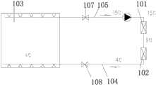
图1是现有技术的示意图;Fig. 1 is the schematic diagram of prior art;
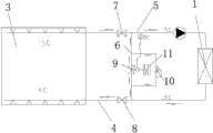
图2是本实用新型的示意图;Fig. 2 is the schematic diagram of the utility model;
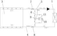
图3是本实用新型中间状态的示意图;Fig. 3 is the schematic diagram of the intermediate state of the utility model;
图4是本实用新型稳定状态的示意图。Fig. 4 is a schematic diagram of the steady state of the utility model.
具体实施方式Detailed ways
下面结合附图和具体实施例对本实用新型进行详细的说明。Below in conjunction with accompanying drawing and specific embodiment the utility model is described in detail.
图1为采用两台主机串联的水蓄冷装置,包括第一级主机101、第二级主机102、蓄冷水池103和蓄冷水池的进水管104和出水管105,进出水管在蓄冷水池一侧分别设有控制阀107和108。第二级主机的出水温度为4度冷水。当主机刚启动时,出水温度达不到4度,此时直接送入蓄冷水池103中,会破坏蓄冷水池的稳定性。而且,主机采用两极压缩,成本高。Fig. 1 is the water cold storage device that adopts two hosts to be connected in series, including the
图2是本实用新型提出的大温差水蓄冷装置,包括制冷主机1、蓄冷水池3和与蓄冷水池连接的进水管4和出水管5,还包括一连接在蓄冷水池进出水管之间的旁通6,进出水管在蓄冷水池一侧分别设有控制阀7和8。旁通6上设有流量调节装置。该流量控制装置包括相互并联的电动调节阀9和定流量阀10。电动调节阀9与设置在主机进水侧的温度传感器连接并由电动阀驱动器11控制。Fig. 2 is a large temperature difference water cold storage device proposed by the utility model, which includes a
工作时,分以下三种状态:When working, it can be divided into the following three states:
1、开启状态,蓄冷过程开始,水泵启动,制冷主机1未启动,此时,电动调节阀9全开,定流量阀10开启。制冷主机进出水温度均为摄氏15度,如图2所示。1. In the open state, the cold storage process starts, the water pump starts, and the
2、中间状态,蓄冷过程,水泵开启,制冷主机1开启,出水管5部分开启,电动调节阀9部分开启,定流量阀10开启。主机进出水温度逐步降低,如图3所示。2. In the intermediate state, during the cold storage process, the water pump is turned on, the
3、稳定状态,水泵开启,制冷主机1开启,电动调节阀9和定流量阀10关闭。主机进出水温度为摄氏9度,出水温度为摄氏4度,如图4所示。3. In a stable state, the water pump is turned on, the
本实用新型采用旁通6,使蓄冷水池出水管5中的冷冻水与高温水汇合的方式,使蓄冷启动时进入制冷主机的温度逐步降低,不仅提高了制冷主机的工作效率,而且保证了蓄冷水池的稳定性,此外,使制冷主机采用一级工作模式,降级了使用和维护的成本。The utility model adopts the
本实用新型有效地解决了大温差水蓄冷运行的问题,使单台主机支持大温差运行工况,结构简单,成本低,稳定性好。The utility model effectively solves the problem of large temperature difference water cold storage operation, enables a single main engine to support the operation condition of large temperature difference, has simple structure, low cost and good stability.
Claims (3)
Translated fromChinesePriority Applications (1)
| Application Number | Priority Date | Filing Date | Title |
|---|---|---|---|
| CN2013202598769UCN203274097U (en) | 2013-05-14 | 2013-05-14 | Large temperature difference water cold accumulation device |
Applications Claiming Priority (1)
| Application Number | Priority Date | Filing Date | Title |
|---|---|---|---|
| CN2013202598769UCN203274097U (en) | 2013-05-14 | 2013-05-14 | Large temperature difference water cold accumulation device |
Publications (1)
| Publication Number | Publication Date |
|---|---|
| CN203274097Utrue CN203274097U (en) | 2013-11-06 |
Family
ID=49504496
Family Applications (1)
| Application Number | Title | Priority Date | Filing Date |
|---|---|---|---|
| CN2013202598769UExpired - LifetimeCN203274097U (en) | 2013-05-14 | 2013-05-14 | Large temperature difference water cold accumulation device |
Country Status (1)
| Country | Link |
|---|---|
| CN (1) | CN203274097U (en) |
Cited By (2)
| Publication number | Priority date | Publication date | Assignee | Title |
|---|---|---|---|---|
| CN107477735A (en)* | 2017-07-21 | 2017-12-15 | 深圳达实智能股份有限公司 | Chilled water storage system |
| CN108224643A (en)* | 2018-02-07 | 2018-06-29 | 杨伟国 | Bypass flow thermostat and water energy storage system using same |
- 2013
- 2013-05-14CNCN2013202598769Upatent/CN203274097U/ennot_activeExpired - Lifetime
Cited By (2)
| Publication number | Priority date | Publication date | Assignee | Title |
|---|---|---|---|---|
| CN107477735A (en)* | 2017-07-21 | 2017-12-15 | 深圳达实智能股份有限公司 | Chilled water storage system |
| CN108224643A (en)* | 2018-02-07 | 2018-06-29 | 杨伟国 | Bypass flow thermostat and water energy storage system using same |
Similar Documents
| Publication | Publication Date | Title |
|---|---|---|
| CN102705939B (en) | Closed cooling tower refrigerating system applied to IDC (Internet Data Center) room and refrigerating method thereof | |
| CN204301358U (en) | Phase change cold-storage formula LNG cold energy utilization device | |
| CN103234250B (en) | A kind of water cool-storage technology system and operation method thereof | |
| CN102252488B (en) | Control method of refrigerator condenser heat radiating system | |
| CN108266778B (en) | Heat pump heating system and heat pump heating method | |
| CN204991904U (en) | Battery thermal management system | |
| CN104236148A (en) | Edible mushroom refrigeration house energy-saving refrigeration system | |
| CN203478468U (en) | Chilled water storage air conditioning system | |
| CN103363723A (en) | Active recovery system and active recovery method for balancing heat extraction and heat removal of ground heat exchanger | |
| CN203274097U (en) | Large temperature difference water cold accumulation device | |
| CN204243158U (en) | A liquid-cooled battery system for new energy vehicles | |
| CN102072541A (en) | Cold storage type solar injection-compression combined refrigerator set | |
| CN202032911U (en) | Evacuation system for steam condenser | |
| CN202153039U (en) | Low-load high-efficiency energy-storage operation system of centralized air conditioner | |
| CN202630268U (en) | Indirect cooling type chilled water storage air conditioning system | |
| CN107719151B (en) | Heat storage system, control method of heat storage system and vehicle | |
| CN101440976A (en) | Energy storage enthalpy increasing heat pump heat supply system | |
| CN105135728A (en) | Low-temperature air-cooled heat pump system | |
| CN202630267U (en) | Direct cold supply type water cold storage air conditioning system | |
| CN204678683U (en) | An a kind of heating type heat pump hot water | |
| CN204648766U (en) | There is the evaporative condenser of defroster | |
| CN203010996U (en) | Rapid refrigeration system utilizing liquid nitrogen | |
| CN208011961U (en) | Bypass thermostat and water energy storage system using the thermostat | |
| CN107289726A (en) | Double refrigeration car refrigerators and its control method and controller | |
| CN104101055A (en) | Control method of water-cooled air conditioner |
Legal Events
| Date | Code | Title | Description |
|---|---|---|---|
| C14 | Grant of patent or utility model | ||
| GR01 | Patent grant | ||
| CX01 | Expiry of patent term | ||
| CX01 | Expiry of patent term | Granted publication date:20131106 |