CN203223412U - Spindle type bulb tubular pump device - Google Patents
Spindle type bulb tubular pump deviceDownload PDFInfo
- Publication number
- CN203223412U CN203223412UCN 201320222816CN201320222816UCN203223412UCN 203223412 UCN203223412 UCN 203223412UCN 201320222816CN201320222816CN 201320222816CN 201320222816 UCN201320222816 UCN 201320222816UCN 203223412 UCN203223412 UCN 203223412U
- Authority
- CN
- China
- Prior art keywords
- bulb
- bulb body
- pump device
- spindle type
- flow channel
- Prior art date
- Legal status (The legal status is an assumption and is not a legal conclusion. Google has not performed a legal analysis and makes no representation as to the accuracy of the status listed.)
- Expired - Fee Related
Links
- XLYOFNOQVPJJNP-UHFFFAOYSA-NwaterSubstancesOXLYOFNOQVPJJNP-UHFFFAOYSA-N0.000claimsabstractdescription22
- 239000007769metal materialSubstances0.000claimsabstractdescription4
- 238000009987spinningMethods0.000claimsdescription13
- 238000003466weldingMethods0.000abstractdescription3
- 230000003247decreasing effectEffects0.000abstract1
- 238000005086pumpingMethods0.000description4
- 238000009434installationMethods0.000description3
- 238000009792diffusion processMethods0.000description1
- 230000009365direct transmissionEffects0.000description1
- 238000000034methodMethods0.000description1
Images
Landscapes
- Structures Of Non-Positive Displacement Pumps (AREA)
Abstract
Description
Translated fromChinese技术领域technical field
本实用新型涉及灯泡贯流泵装置,特别是纺锥型灯泡贯流泵装置的结构形式,属于泵站装置技术领域。The utility model relates to a bulb through-flow pump device, in particular to the structural form of a spinning cone type bulb through-flow pump device, and belongs to the technical field of pumping station devices.
背景技术Background technique
灯泡贯流泵作为适应较低扬程的泵型,具有扬程低、流量大、卧式布置、机组结构紧凑等特点,具有流道顺直、水力损失小、装置效率高等优点。其主要特点是电机安装在灯泡体内,保证了电动机与水泵的直接传动。但目前国内已建的灯泡贯流泵站灯泡体较短,电机安装空间小,同时存在泵站效率未达到预期设计要求。As a pump type suitable for lower head, the bulb tubular pump has the characteristics of low head, large flow, horizontal arrangement, compact unit structure, etc., and has the advantages of straight flow path, small hydraulic loss and high installation efficiency. Its main feature is that the motor is installed in the bulb body, which ensures the direct transmission between the motor and the water pump. But at present, the bulb tubular pumping station built in China has a short bulb body, small space for motor installation, and the efficiency of the pumping station does not meet the expected design requirements.
实用新型内容Utility model content
本实用新型的目的就是针对上述现有灯泡贯流泵存在的不足,要解决灯泡贯流泵电机安装空间问题和灯泡部分设计不当引起的泵站效率低的问题,提供一种结构形式简单,泵装置整体效率高的纺锥型灯泡贯流泵装置。The purpose of this utility model is to solve the problem of the installation space of the motor of the bulb tubular pump and the problem of low efficiency of the pump station caused by the improper design of the bulb part, and to provide a pump with a simple structure. Spinning cone type bulb tubular pump device with high overall efficiency of the device.
本实用新型的目的是这样实现的,纺锥型灯泡贯流泵装置,包括依次设置连接的进水流道、叶轮、导叶、出水流道和设置在出水流道中的灯泡体,其特征是,所述灯泡体为纺锥型,导叶及灯泡体出口边单边扩散角为7度。The purpose of this utility model is achieved in this way, the spinning cone type bulb through-flow pump device includes a connected water inlet channel, an impeller, a guide vane, an outlet channel and a bulb body arranged in the outlet channel in sequence, and is characterized in that, The bulb body is a spinning cone, and the unilateral divergence angle of the guide vane and the outlet side of the bulb body is 7 degrees.
所述纺锥型灯泡体为对半结构,采用金属材料焊接构成。The spun-cone bulb body is a half structure, which is formed by welding metal materials.
所述出水流道为混凝土结构。The water outlet channel is a concrete structure.
所述纺锥型灯泡体的长度为所述叶轮直径的5.3倍。The length of the spin-cone bulb body is 5.3 times the diameter of the impeller.
所述纺锥型灯泡体的最大宽度为所述叶轮直径的0.95倍。The maximum width of the spin-cone bulb body is 0.95 times the diameter of the impeller.
本实用新型结构合理简单,基于流道内流速均匀扩散原理,避免流速的突然减少引起的水力损失增加,灯泡贯流泵的灯泡体形状采用纺锥型,导叶及灯泡体出口边单边扩散角为7度。该纺锥型灯泡贯流泵装置相对于传统灯泡贯流泵出水水力损失大大减小,能有效地降低工程投资和运行成本,保证机组安全高效可靠运行,有效地提高了装置效率,节约了能源。The utility model has a reasonable and simple structure, and is based on the principle of uniform diffusion of the flow velocity in the flow channel to avoid the increase of hydraulic loss caused by the sudden decrease of the flow velocity. is 7 degrees. Compared with the traditional bulb tubular pump, the spin-cone bulb tubular pump device greatly reduces the hydraulic loss of the outlet water, which can effectively reduce the project investment and operating costs, ensure the safe, efficient and reliable operation of the unit, effectively improve the efficiency of the device, and save energy. .
附图说明Description of drawings
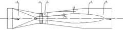
图1是本实用新型的纵剖面结构示意图。Fig. 1 is a schematic view of the longitudinal section of the utility model.
图中:1.叶轮 ,2. 导叶,3. 纺锥型灯泡体 ,4.出水流道,5.进水流道。In the figure: 1. impeller, 2. guide vane, 3. spinning cone bulb body, 4. water outlet channel, 5. water inlet channel.
具体实施方式Detailed ways
一种纺锥型灯泡贯流泵装置,包括叶轮1、导叶2、纺锥型灯泡体3 、出水流道4、进水流道5,进水流道、叶轮、导叶、出水流道依次设置连接,纺锥型灯泡体设置在出水流道中。导叶及灯泡体出口边单边扩散角为7度。纺锥型灯泡体为对半结构,采用金属材料焊接构成。出水流道采用混凝土立木模浇注成型为混凝土结构。纺锥型灯泡体的长度为所述叶轮直径的5.3倍,纺锥型灯泡体的最大宽度为所述叶轮直径的0.95倍。本实用新型可在大中型泵站中实施,能有效地降低工程投资和运行成本,保证机组安全高效可靠运行,取得较大的经济效益和社会效益。A spinning cone bulb tubular pump device, comprising an impeller 1, a guide vane 2, a spinning cone bulb body 3, a water outlet channel 4, and a water inlet channel 5, and the water inlet channel, impeller, guide vane, and water outlet channel are arranged in sequence connected, the spinning cone bulb body is set in the water outlet channel. The unilateral divergence angle of the guide vane and the outlet side of the bulb body is 7 degrees. The spinning cone bulb body is a half structure, which is formed by welding metal materials. The outlet flow channel is cast into a concrete structure using concrete vertical wooden molds. The length of the spinning cone bulb body is 5.3 times the diameter of the impeller, and the maximum width of the spinning cone bulb body is 0.95 times the diameter of the impeller. The utility model can be implemented in large and medium-sized pumping stations, can effectively reduce project investment and operating costs, ensure safe, efficient and reliable operation of the unit, and achieve greater economic and social benefits.
Claims (5)
Translated fromChinesePriority Applications (1)
| Application Number | Priority Date | Filing Date | Title |
|---|---|---|---|
| CN 201320222816CN203223412U (en) | 2013-04-27 | 2013-04-27 | Spindle type bulb tubular pump device |
Applications Claiming Priority (1)
| Application Number | Priority Date | Filing Date | Title |
|---|---|---|---|
| CN 201320222816CN203223412U (en) | 2013-04-27 | 2013-04-27 | Spindle type bulb tubular pump device |
Publications (1)
| Publication Number | Publication Date |
|---|---|
| CN203223412Utrue CN203223412U (en) | 2013-10-02 |
Family
ID=49250416
Family Applications (1)
| Application Number | Title | Priority Date | Filing Date |
|---|---|---|---|
| CN 201320222816Expired - Fee RelatedCN203223412U (en) | 2013-04-27 | 2013-04-27 | Spindle type bulb tubular pump device |
Country Status (1)
| Country | Link |
|---|---|
| CN (1) | CN203223412U (en) |
Cited By (3)
| Publication number | Priority date | Publication date | Assignee | Title |
|---|---|---|---|---|
| CN105715586A (en)* | 2016-01-19 | 2016-06-29 | 扬州大学 | Excellent-hydraulic-performance inlet conduit of tubular-type axial flow pump device with front-mounted bulb and application method |
| CN106499670A (en)* | 2016-10-28 | 2017-03-15 | 扬州大学 | Pump installation outlet passage with secondary stator |
| CN108223386A (en)* | 2017-11-30 | 2018-06-29 | 河海大学 | A kind of large-scale bulb through-flow pump installation |
- 2013
- 2013-04-27CNCN 201320222816patent/CN203223412U/ennot_activeExpired - Fee Related
Cited By (4)
| Publication number | Priority date | Publication date | Assignee | Title |
|---|---|---|---|---|
| CN105715586A (en)* | 2016-01-19 | 2016-06-29 | 扬州大学 | Excellent-hydraulic-performance inlet conduit of tubular-type axial flow pump device with front-mounted bulb and application method |
| CN105715586B (en)* | 2016-01-19 | 2017-09-08 | 扬州大学 | A kind of bulb forward type tubular pump water inlet flow channel and application process |
| CN106499670A (en)* | 2016-10-28 | 2017-03-15 | 扬州大学 | Pump installation outlet passage with secondary stator |
| CN108223386A (en)* | 2017-11-30 | 2018-06-29 | 河海大学 | A kind of large-scale bulb through-flow pump installation |
Similar Documents
| Publication | Publication Date | Title |
|---|---|---|
| CN108361205B (en) | Centrifugal pump impeller and LNG immersed pump comprising same | |
| CN203223412U (en) | Spindle type bulb tubular pump device | |
| CN203604216U (en) | Bulb type diving tubular pump device | |
| CN102182706B (en) | S-shaped downwards horizontal axis-extending tubular pump device | |
| CN203741796U (en) | Water filling pressure and flatting structure used for long water diversion tunnel valve | |
| CN204572559U (en) | A kind of open type water inlet pool 1/4 elliptical horn pipe | |
| CN205744492U (en) | A kind of environmental protection water pump of green energy conservation | |
| CN203223390U (en) | Novel postposition bulb tubular pump | |
| CN202768220U (en) | Water turbine runner fixing device | |
| CN204942089U (en) | A kind of through-flow pump diffusion diffuser | |
| CN203303768U (en) | Gas filter | |
| CN203321859U (en) | Low-lift bidirectional vertical shaft tubular pump device | |
| CN202900790U (en) | Centrifugal water pump | |
| CN202091206U (en) | Combined type tubular pump device of water outlet structure | |
| CN204738974U (en) | A high-efficiency single-stage pump | |
| CN203853002U (en) | High-gas-amount molecular sieve absorbing tower | |
| CN204200671U (en) | The turbo-charger blower impeller that runoff and oblique flow combine | |
| CN202108637U (en) | Tail water device of water turbine | |
| CN203146407U (en) | Rear vertical shaft tubular pump device with front guide vane | |
| CN201396234Y (en) | A special ultra-low specific speed Francis turbine runner for cooling tower fan drive | |
| CN202073688U (en) | Mixed flow low specific speed compensating water turbine | |
| CN201705730U (en) | Volute type structure of tangent pump body | |
| CN204400977U (en) | Wine brewing condensing works | |
| CN206111672U (en) | Novel two -way shaft through -flow pump runner structure | |
| CN202811169U (en) | Low-wind-drag high-flux water turbine volute shell |
Legal Events
| Date | Code | Title | Description |
|---|---|---|---|
| C14 | Grant of patent or utility model | ||
| GR01 | Patent grant | ||
| CF01 | Termination of patent right due to non-payment of annual fee | ||
| CF01 | Termination of patent right due to non-payment of annual fee | Granted publication date:20131002 Termination date:20170427 |