CN203150710U - Antenna switching system - Google Patents
Antenna switching systemDownload PDFInfo
- Publication number
- CN203150710U CN203150710UCN 201220708680CN201220708680UCN203150710UCN 203150710 UCN203150710 UCN 203150710UCN 201220708680CN201220708680CN 201220708680CN 201220708680 UCN201220708680 UCN 201220708680UCN 203150710 UCN203150710 UCN 203150710U
- Authority
- CN
- China
- Prior art keywords
- antenna
- switching system
- antenna switching
- control assembly
- circuit
- Prior art date
- Legal status (The legal status is an assumption and is not a legal conclusion. Google has not performed a legal analysis and makes no representation as to the accuracy of the status listed.)
- Expired - Fee Related
Links
- 238000009434installationMethods0.000claims2
- 238000013461designMethods0.000abstractdescription3
- 230000005540biological transmissionEffects0.000description10
- 238000005516engineering processMethods0.000description8
- 238000004891communicationMethods0.000description7
- 238000010295mobile communicationMethods0.000description7
- 238000010586diagramMethods0.000description4
- 230000007774longtermEffects0.000description4
- 230000001413cellular effectEffects0.000description1
- 238000011161developmentMethods0.000description1
- 230000000694effectsEffects0.000description1
- 238000004519manufacturing processMethods0.000description1
- 238000000034methodMethods0.000description1
- 238000012986modificationMethods0.000description1
- 230000004048modificationEffects0.000description1
Images

Landscapes
- Transceivers (AREA)
Abstract
Translated fromChineseDescription
Translated fromChinese技术领域technical field
本实用新型涉及一种天线切换系统,尤其涉及一种利用电子装置上邻近一天线模块的控制组件直接输出一控制讯号至天线模块的开关以选择切换到不同频段的天线的天线切换系统。 The utility model relates to an antenna switching system, in particular to an antenna switching system which utilizes a control component adjacent to an antenna module on an electronic device to directly output a control signal to a switch of the antenna module to select and switch to antennas of different frequency bands. the
背景技术Background technique
近年来,无线通信快速发展,计算机、移动电话等个人化电子产品连接至无线网络,上传或下载数据量庞大的多媒体档案已成常态,个人化电子产品需通过无线装置,支持高速的数据传输,因此多输入多输出(Multiple-input Multiple-out,MIMO)天线系统的应用越来越广泛。根据不同的通讯技术,已知技术已发展出许多不同的行动通讯系统,如全球行动通讯系统(Global System for Mobile Communications,GSM)、分码多任务接取(Code Division Multiple Access,CDMA)通讯系统、宽带分码多任务接取(Wideband Code Division Multiple Access,WCDMA)通讯系统、个人数字移动电话(Personal Digital Cellular,PDC)系统、个人手持式电话系统(Personal Handyphone System,PHS)、全球互通微波存取(Worldwide Interoperability for Microwave Access,WiMAX)及长期演进技术(Long Term Evolution,LTE)等。一般而言,不同的行动通讯系统其操作频段都尽可能地相异而不与其它行动通讯系统重迭。例如,全球行动通讯系统可根据操作频率的不同,分为欧规900兆赫(MHz)、1800兆赫及美规850兆赫及1900兆赫的全球行动通讯系统。900兆赫的全球行动通讯系统(以下简称GSM900系统)的接收频段介于925.2兆赫与959.8兆赫之间,而传输频段则介于880.2兆赫与914.8兆赫之间;1800兆赫的全球行动通讯系统(Digital Communication System,DCS,以下简称DCS1800系统)的接收频段介于1805.2兆赫与1879.8兆赫之间,而传输频段则介于1710.2兆赫与1784.8兆赫之间;850兆赫的全球行动通讯系统(以下简称GSM850系统)的接收频段介 于869兆赫与894兆赫之间,而传输频段则介于824兆赫与849兆赫之间;1900兆赫的全球行动通讯系统(Personal Communication System,PCS,以下简称PCS1900系统)的接收频段介于1930兆赫与1990兆赫之间,而传输频段则介于1850兆赫与1910兆赫之间;另外,目前已由第3.5代(3.5G)通讯技术逐渐迈入第4代(4G)通讯技术中,如长期演进技术(long term evolution,LTE)是目前业界所推动的新一代行动无线宽带技术之一,LTE频段扩展度好,支持1.4MHZ至20MHZ的分时多重进接和分码多重进接频段。一般笔记本电脑均设有欧规及美规的天线,且藉由一天线切换装置,依据所需的天线规格作切换,然而一般天线均设于笔记本电脑的屏幕的上框边缘处,且藉由一传输线连接天线与主板,并藉由主板传输一控制讯号至该天线开关,以控制切换至不同的天线规格,但现今笔记本电脑追求轻、薄、短、小的风潮下,其组件与组件间的走线空间变得相当有限,因此如何缩短及减少组件与组件间的走线的问题,实为亟需解决的问题。 In recent years, with the rapid development of wireless communication, personal electronic products such as computers and mobile phones are connected to wireless networks, and uploading or downloading multimedia files with a large amount of data has become the norm. Personal electronic products need to support high-speed data transmission through wireless devices. Therefore, multiple-input multiple-out (Multiple-input Multiple-out, MIMO) antenna systems are more and more widely used. According to different communication technologies, known technologies have developed many different mobile communication systems, such as Global System for Mobile Communications (GSM), Code Division Multiple Access (CDMA) communication systems , Wideband Code Division Multiple Access (WCDMA) communication system, Personal Digital Cellular (PDC) system, Personal Handyphone System (PHS), Global Interoperability Microwave Storage Take (Worldwide Interoperability for Microwave Access, WiMAX) and long-term evolution technology (Long Term Evolution, LTE), etc. Generally speaking, the operating frequency bands of different mobile communication systems are as different as possible without overlapping with other mobile communication systems. For example, GSM can be divided into 900 MHz and 1800 MHz for European regulations and 850 MHz and 1900 MHz for US regulations according to different operating frequencies. The 900 MHz Global System for Mobile Communication (hereinafter referred to as the GSM900 system) has a receiving frequency band between 925.2 MHz and 959.8 MHz, and a transmission frequency band between 880.2 MHz and 914.8 MHz; the 1800 MHz Global System for Mobile Communication (Digital Communication) System, DCS, hereinafter referred to as DCS1800 system) the receiving frequency band is between 1805.2 MHz and 1879.8 MHz, while the transmission frequency band is between 1710.2 MHz and 1784.8 MHz; the 850 MHz global mobile communication system (hereinafter referred to as GSM850 system) The receiving frequency band is between 869 MHz and 894 MHz, while the transmitting frequency band is between 824 MHz and 849 MHz; Between 1930 MHz and 1990 MHz, while the transmission frequency band is between 1850 MHz and 1910 MHz; in addition, the 3.5th generation (3.5G) communication technology has gradually entered the 4th generation (4G) communication technology, such as Long term evolution technology (long term evolution, LTE) is one of the new generation of mobile wireless broadband technologies promoted by the industry. The LTE frequency band has a good degree of expansion and supports time-division multiple access and code-division multiple access frequency bands from 1.4MHZ to 20MHZ. General notebook computers are equipped with European and American antennas, and an antenna switching device is used to switch according to the required antenna specifications. A transmission line connects the antenna and the main board, and transmits a control signal to the antenna switch through the main board to control switching to different antenna specifications. The space for wiring becomes quite limited, so how to shorten and reduce the wiring between components is an urgent problem to be solved. the
中国台湾公告第M432216号专利案,揭示一种无线网络及视讯读取的整合模块,包括:一电路板、一无线局域网络接口、一视讯接口及一传输接口,其中将视讯接口及无线局域网络接口电性固接于该电路板上,以整合成单一模块,再通过该传输接口与该主板电性连结,使笔记本电脑在制作上更加省时、省工序。由上可知,该视讯接口及无线局域网络接口,均藉由传输接口传送讯号至主板或接收由主板发送的讯号至视讯接口及无线局域网络接口,因此虽然减少了高频传输线的设置,但却需额外新增电路板以整合视讯接口及无线局域网络接口,相对地减少规划天线设计所使用的空间。 China Taiwan Announcement No. M432216 patent case discloses an integrated module for wireless network and video reading, including: a circuit board, a wireless local area network interface, a video interface and a transmission interface, wherein the video interface and wireless local area network The interface is electrically fixed on the circuit board to be integrated into a single module, and then electrically connected with the main board through the transmission interface, so that the production of the notebook computer is more time-saving and process-saving. It can be seen from the above that the video interface and the wireless LAN interface both transmit signals to the motherboard through the transmission interface or receive signals sent by the motherboard to the video interface and the wireless LAN interface. Therefore, although the setting of high-frequency transmission lines is reduced, the An additional circuit board needs to be added to integrate the video interface and the wireless local area network interface, which relatively reduces the space used for planning the antenna design. the
实用新型内容Utility model content
有鉴于上述已知技术的问题,本实用新型的目的在于提供一种天线切换系统,利用控制组件输出一控制讯号作为驱动天线切换开关的控制讯号,以控制切换该天线。 In view of the problems of the above-mentioned known technologies, the purpose of the present invention is to provide an antenna switching system, which uses a control component to output a control signal as a control signal for driving the antenna switching switch, so as to control switching of the antenna. the
根据本实用新型的一个实施例的天线切换系统包含:一天线模块、一控制组件及连接该天线模块与该控制组件的线路,该天线模块具有多个不同频段的天线及多个开关,而该多个开关分别对应设置于该多个不同频段 的天线上;而该控制组件邻近该天线模块设置且可与一电子装置的主板电连接,该控制组件输出一控制讯号,经由该线路至该天线模块的该多个开关,可使该多个开关切换到不同频段的天线。 An antenna switching system according to an embodiment of the present invention includes: an antenna module, a control component and a line connecting the antenna module and the control component, the antenna module has a plurality of antennas of different frequency bands and a plurality of switches, and the A plurality of switches are correspondingly arranged on the antennas of the plurality of different frequency bands; and the control component is arranged adjacent to the antenna module and can be electrically connected to the main board of an electronic device, and the control component outputs a control signal to the antenna through the line The multiple switches of the module can switch the multiple switches to antennas of different frequency bands. the
根据本实用新型的一个实施例的天线切换系统,该控制组件为一主动式模块,并具有一预留可供使用者额外规划的线路,藉由该预留可供使用者额外规划的线路输出该控制讯号。 According to an antenna switching system according to an embodiment of the present invention, the control component is an active module, and has a line reserved for additional planning by the user, and the output of the line is reserved for additional planning by the user the control signal. the
根据本实用新型的一个实施例的天线切换系统,该天线模块设置于远离该电子装置的主板的位置处。 According to the antenna switching system of an embodiment of the present invention, the antenna module is disposed at a position away from the main board of the electronic device. the
根据本实用新型的一个实施例的天线切换系统,该主动式模块为一CCD或CMOS或人体传感器。 According to an antenna switching system according to an embodiment of the present invention, the active module is a CCD or CMOS or a human body sensor. the
根据本实用新型的一个实施例的天线切换系统,连接该天线模块与该控制组件的该线路为该控制组件电连接至该主板的部分延伸。 According to an antenna switching system according to an embodiment of the present invention, the line connecting the antenna module and the control component is an extension of the part where the control component is electrically connected to the main board. the
根据本实用新型的一个实施例的天线切换系统,该控制组件连接至该主板的该部分延伸为一软性扁平电缆(FFC)。 According to an embodiment of the antenna switching system of the present invention, the part where the control unit is connected to the main board extends as a flexible flat cable (FFC). the
根据本实用新型的一个实施例的天线切换系统,连接该天线模块与该控制组件的该线路系自该控制组件延伸。 According to the antenna switching system of an embodiment of the present invention, the line connecting the antenna module and the control component is extended from the control component. the
根据本实用新型的一个实施例的天线切换系统,自该控制组件延伸的线路为一软性扁平电缆(FFC)或软性印刷电路板(FPC)。 According to an embodiment of the antenna switching system of the present invention, the line extending from the control unit is a flexible flat cable (FFC) or a flexible printed circuit board (FPC). the
根据本实用新型的一个实施例的天线切换系统,所述预留可供使用者额外规划的线路为一接脚。 According to the antenna switching system of an embodiment of the present invention, the line reserved for additional planning by the user is a pin. the
本实用新型的天线切换系统不仅解决了现有技术中如何缩短及减少组件与组件间的走线的问题,而且相对地增加了规划天线设计所使用的空间。 The antenna switching system of the utility model not only solves the problem of how to shorten and reduce wiring between components in the prior art, but also relatively increases the space used for planning antenna design. the
在参阅下述详细的实施方式及相关的图示与权利要求后,阅者将更能了解本实用新型其他的目的、特征、及优点。 Readers will be able to better understand other objectives, features, and advantages of the present invention after referring to the following detailed embodiments and related drawings and claims. the
附图说明Description of drawings
图1是显示根据本实用新型的一个实施例的天线切换系统的方块图;以及 Fig. 1 is a block diagram showing an antenna switching system according to an embodiment of the present invention; and
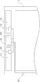
图2是显示根据本实用新型的天线切换系统应用于笔记本电脑的示意 图。 Fig. 2 is a schematic diagram showing that the antenna switching system according to the present invention is applied to a notebook computer. the
具体实施方式Detailed ways
虽然本实用新型将参阅含有本实用新型的优选实施例的所附图式予以充分描述,但在此描述之前应了解本领域的技术人员可修改本文中所描述的实用新型,同时获致本实用新型的功效。因此,须了解以上描述对本领域的技术人员而言为一广泛之揭示,且其内容不在于限制本实用新型。 Although the utility model will be fully described with reference to the accompanying drawings containing preferred embodiments of the utility model, it should be understood that those skilled in the art can modify the utility model described herein while obtaining the utility model. effect. Therefore, it should be understood that the above description is a broad disclosure for those skilled in the art, and its content is not intended to limit the present invention. the
请参阅图1,其显示根据本实用新型的一个实施例的天线切换系统的方块图。本实用新型的天线切换系统100包含:一天线模块10、一控制组件20及连接该天线模块10与该控制组件20的线路21,该天线模块10具有多个不同频段的天线及多个开关,而该多个开关分别对应设置于该多个不同频段的天线上;而该控制组件20邻近该天线模块可与一电子装置的主板30电连接,且通过该控制组件20输出一控制讯号,经由该线路21至该天线模块10的多个开关,可使该多个开关切换到不同频段的天线。 Please refer to FIG. 1 , which shows a block diagram of an antenna switching system according to an embodiment of the present invention. The
请继续参考图1,在本实施例中,该天线模块10的多个不同频段的天线为第一天线11及第二天线12,而该多个开关为第一开关13及第二开关14,而该控制组件20为一主动式模块,该主动式模块可为一CCD或CMOS或人体传感器等的电路,且该控制组件20一般具有预留可供使用者额外规划的线路(接脚),因此本实用新型的天线切换系统100藉由该控制组件20所预留可供使用者额外规划的线路(接脚)输出一控制讯号,经由该线路21至该天线模块10的第一开关13或第二开关14,以控制该第一天线11或第二天线12作动。 Please continue to refer to FIG. 1. In this embodiment, the multiple antennas of different frequency bands of the
请参阅图2,其显示根据本实用新型的一个实施例的天线切换系统应用于一笔记本电脑上的示意图。本实用新型的切换系统置于该笔记本电脑1的屏幕的上框边缘处,如图所示,在本实施例中,该控制组件20为一CCD视讯模块,而该天线模块10的第一天线11与第二天线12设置于该控制组件20(CCD视讯模块)的两侧,该控制组件20(CCD视讯模块)藉由该线路21与该第一天线11及第二天线12电连接,且藉由该控制组件20(CCD视讯模块)的预留可供使用者额外规划的线路(接脚)输出一控制讯号,并传输至该第一天线11上的第一开关13及第二天线上12的第二开关14,以控制 该多个开关切换成不同频段的天线,而该控制组件20(CCD视讯模块)再藉由一传输线22与该主板30(请参考图1)电连接。 Please refer to FIG. 2 , which shows a schematic diagram of an antenna switching system applied to a notebook computer according to an embodiment of the present invention. The switching system of the present utility model is placed at the edge of the upper frame of the screen of the notebook computer 1, as shown in the figure, in this embodiment, the
在本实施例中,该天线模块10设置于邻近该控制组件20且远离该电子装置的主板30的位置处;另外,在本实施例中,连接该天线模块10与该控制组件20的该线路21为由该控制组件20电连接至该主板30的部分延伸,且该控制组件20连接至主板30的该部分延伸为一软性扁平电缆(FFC)或软性印刷电路板(FPC),或者为由印刷电路板(PCB)的布局的走线,或可为单芯线、多芯线及同轴线;而连接该天线模块10与该控制组件20的该线路21自该控制组件20延伸,其中自该控制组件延伸的该线路也为一软性扁平电缆(FFC)或软性印刷电路板(FPC),或者为由印刷电路板(PCB)的布局的走线,或可为单芯线、多芯线及同轴线。 In this embodiment, the
前述电子装置仅以笔记本电脑1举例说明本实用新型而非限制,实际上,该电子装置可为一可移动装置、一移动电话、一卫星定位装置(Global Positioning System,GPS)、一掌上型游戏设备、一个人数字助理(Personal Digital Assistance,PDA)等,以收纳各类型的天线模块,而本实用新型的天线切换系统的控制组件也可为一CCD或CMOS或人体传感器等的主动式模块,并藉由该控制组件的预留可供使用者额外规划的线路(接脚),输出一控制讯号作为天线切换开关的控制讯号。 Aforesaid electronic device only uses notebook computer 1 as an example to illustrate the utility model and is not limited, in fact, this electronic device can be a mobile device, a mobile phone, a satellite positioning device (Global Positioning System, GPS), a palm-sized game equipment, a personal digital assistant (Personal Digital Assistance, PDA), etc., to accommodate various types of antenna modules, and the control component of the antenna switching system of the present utility model can also be an active module such as a CCD or CMOS or a human body sensor. And through the reserved lines (pins) of the control component that can be additionally planned by the user, a control signal is output as the control signal of the antenna switching switch. the
以上所述仅为举例性,而非为限制性。任何未脱离本实用新型的精神与范畴,而对其进行的等效修改或变更,均应包含于权利要求范围中。应注意,措词“包括”不排除其它元件或步骤,措词“一”或“一个”不排除多个。另外,权利要求的任何元件标号不应理解为限制本实用新型的范围。 The above description is for illustration only, not for limitation. Any equivalent modification or change made without departing from the spirit and scope of the present utility model shall be included in the scope of the claims. It should be noted that the word "comprising" does not exclude other elements or steps, and the word "a" or "an" does not exclude a plurality. Additionally, any element references in the claims should not be construed as limiting the scope of the present invention. the
Claims (9)
Priority Applications (1)
| Application Number | Priority Date | Filing Date | Title |
|---|---|---|---|
| CN 201220708680CN203150710U (en) | 2012-12-19 | 2012-12-19 | Antenna switching system |
Applications Claiming Priority (1)
| Application Number | Priority Date | Filing Date | Title |
|---|---|---|---|
| CN 201220708680CN203150710U (en) | 2012-12-19 | 2012-12-19 | Antenna switching system |
Publications (1)
| Publication Number | Publication Date |
|---|---|
| CN203150710Utrue CN203150710U (en) | 2013-08-21 |
Family
ID=48978210
Family Applications (1)
| Application Number | Title | Priority Date | Filing Date |
|---|---|---|---|
| CN 201220708680Expired - Fee RelatedCN203150710U (en) | 2012-12-19 | 2012-12-19 | Antenna switching system |
Country Status (1)
| Country | Link |
|---|---|
| CN (1) | CN203150710U (en) |
Cited By (3)
| Publication number | Priority date | Publication date | Assignee | Title |
|---|---|---|---|---|
| WO2016161632A1 (en)* | 2015-04-10 | 2016-10-13 | 华为技术有限公司 | Antenna configuration method and apparatus, and terminal |
| CN109379104A (en)* | 2018-09-19 | 2019-02-22 | 广州市中海达测绘仪器有限公司 | A kind of radio frequency link switching system |
| CN114447588A (en)* | 2020-11-03 | 2022-05-06 | 英业达科技有限公司 | Antenna structure and electronic device |
- 2012
- 2012-12-19CNCN 201220708680patent/CN203150710U/ennot_activeExpired - Fee Related
Cited By (4)
| Publication number | Priority date | Publication date | Assignee | Title |
|---|---|---|---|---|
| WO2016161632A1 (en)* | 2015-04-10 | 2016-10-13 | 华为技术有限公司 | Antenna configuration method and apparatus, and terminal |
| CN109379104A (en)* | 2018-09-19 | 2019-02-22 | 广州市中海达测绘仪器有限公司 | A kind of radio frequency link switching system |
| CN114447588A (en)* | 2020-11-03 | 2022-05-06 | 英业达科技有限公司 | Antenna structure and electronic device |
| CN114447588B (en)* | 2020-11-03 | 2024-01-26 | 英业达科技有限公司 | Antenna structure and electronic device |
Similar Documents
| Publication | Publication Date | Title |
|---|---|---|
| US9484633B2 (en) | Loop antenna having a parasitically coupled element | |
| CN114284721A (en) | An antenna device and electronic equipment | |
| US11721899B2 (en) | Front-end modules with ground plane slots | |
| TWI407820B (en) | Wireless communication module, portable device using the same and method for manufacturing the same | |
| CN105490025A (en) | Antenna frequency band adjusting apparatus and method | |
| CN203150710U (en) | Antenna switching system | |
| US8730107B2 (en) | Multi-frequency antenna | |
| TWI450505B (en) | Wireless communication device and portable electronic device | |
| CN111478049A (en) | an electronic device | |
| CN111836452A (en) | A printed circuit board kit and wireless communication device | |
| US20120133572A1 (en) | Antenna | |
| CN201438504U (en) | A multi-frequency antenna | |
| CN103633436B (en) | A kind of antenna installation and there is the electronics of this antenna installation | |
| JP5263998B2 (en) | Data communication terminal equipped with multiple antennas such as an antenna for MIMO communication | |
| CN206472169U (en) | Board structure of circuit, antenna assembly and mobile terminal | |
| US12149002B2 (en) | Antenna array, FPC and electronic device | |
| CN103973327A (en) | Mobile communication device | |
| TWM454045U (en) | Antenna switching system | |
| US20120146859A1 (en) | Wireless communication apparatus | |
| CN113660047A (en) | RF cable detection method and mobile terminal | |
| CN106878502B (en) | Circuit board structure, antenna device and mobile terminal | |
| CN104092006B (en) | Electronic equipment and antenna assembly | |
| CN104701640A (en) | Electronic device | |
| CN212908079U (en) | Antenna module and electronic equipment | |
| KR20090118139A (en) | Integrated external antenna for mobile communication terminal supporting various additional services and mobile communication terminal using same |
Legal Events
| Date | Code | Title | Description |
|---|---|---|---|
| C14 | Grant of patent or utility model | ||
| GR01 | Patent grant | ||
| CF01 | Termination of patent right due to non-payment of annual fee | ||
| CF01 | Termination of patent right due to non-payment of annual fee | Granted publication date:20130821 Termination date:20211219 |