CN203144585U - Scattering device for roving tail yarn treater - Google Patents
Scattering device for roving tail yarn treaterDownload PDFInfo
- Publication number
- CN203144585U CN203144585UCN2013200436948UCN201320043694UCN203144585UCN 203144585 UCN203144585 UCN 203144585UCN 2013200436948 UCN2013200436948 UCN 2013200436948UCN 201320043694 UCN201320043694 UCN 201320043694UCN 203144585 UCN203144585 UCN 203144585U
- Authority
- CN
- China
- Prior art keywords
- air
- admission hole
- suction pipe
- air admission
- air inlet
- Prior art date
- Legal status (The legal status is an assumption and is not a legal conclusion. Google has not performed a legal analysis and makes no representation as to the accuracy of the status listed.)
- Expired - Fee Related
Links
- 238000007664blowingMethods0.000claimsabstractdescription27
- 238000003860storageMethods0.000claimsabstractdescription17
- 229920000742CottonPolymers0.000claimsabstractdescription13
- 230000000694effectsEffects0.000abstractdescription3
- 239000012535impuritySubstances0.000abstractdescription2
- 238000004519manufacturing processMethods0.000abstractdescription2
- 239000010902strawSubstances0.000description6
- 210000000683abdominal cavityAnatomy0.000description2
- 238000000034methodMethods0.000description2
- 239000004753textileSubstances0.000description2
- 238000004140cleaningMethods0.000description1
- 230000007547defectEffects0.000description1
- 239000006185dispersionSubstances0.000description1
- 230000008676importEffects0.000description1
- 238000004064recyclingMethods0.000description1
- 238000009987spinningMethods0.000description1
- 239000002699waste materialSubstances0.000description1
Images


Classifications
- Y—GENERAL TAGGING OF NEW TECHNOLOGICAL DEVELOPMENTS; GENERAL TAGGING OF CROSS-SECTIONAL TECHNOLOGIES SPANNING OVER SEVERAL SECTIONS OF THE IPC; TECHNICAL SUBJECTS COVERED BY FORMER USPC CROSS-REFERENCE ART COLLECTIONS [XRACs] AND DIGESTS
- Y02—TECHNOLOGIES OR APPLICATIONS FOR MITIGATION OR ADAPTATION AGAINST CLIMATE CHANGE
- Y02W—CLIMATE CHANGE MITIGATION TECHNOLOGIES RELATED TO WASTEWATER TREATMENT OR WASTE MANAGEMENT
- Y02W30/00—Technologies for solid waste management
- Y02W30/50—Reuse, recycling or recovery technologies
- Y02W30/66—Disintegrating fibre-containing textile articles to obtain fibres for re-use
Landscapes
- Preliminary Treatment Of Fibers (AREA)
Abstract
Translated fromChinese
Description
Translated fromChinese技术领域technical field
本实用新型涉及一种纺织设备,具体的说是用于粗纱尾纱处理机上的打散装置,属纺织技术领域。 The utility model relates to a textile device, in particular to a breaking device for a roving tail processing machine, which belongs to the technical field of textiles. the
背景技术Background technique
打散装置是粗纱尾纱处理机上的关键装置,只有通过该装置,才能将粗纱机和细纱机上的不能完全利用的尾纱进行彻底打散后回收和利用。传统打散装置包括吸管、气缸、气道、涡轮风机和储棉袋及相关连接件。当尾纱纱管经过识别系统确定为尾纱后,便通过专门输送轨道进入尾纱处理机,这时气缸便启动弹出作用杆,带动吸管到达尾纱管,吸管将尾纱管上的尾纱吸入吸管内,同时涡轮风机将吸管中的纱线吸入到涡轮风机腹腔中,通过叶轮将吸入的纱线进行高负压打散,涡轮风机中的纱线被打散后通过排风口吹到储棉袋中,从而完成粗纱尾纱管上尾纱的打散处理。这种沿用的传统装置所存在的问题是:打散效果不彻底,有时从涡轮风机排风口吹出来的纱线未被完全打散,需要人工进行除杂,不仅费时费力,还造成部分棉线的浪费,影响其完全回收利用。The breaking up device is the key device on the roving tail yarn processing machine. Only through this device can the tail yarn that cannot be fully utilized on the roving frame and spinning frame be completely broken up and then recycled and utilized. The traditional breaking device includes a suction pipe, a cylinder, an air channel, a turbo blower, a cotton storage bag and related connectors. When the tail yarn bobbin is determined as tail yarn by the identification system, it enters into the tail yarn processing machine through a special conveying track. It is sucked into the suction pipe, and at the same time, the turbo fan sucks the yarn in the suction pipe into the abdominal cavity of the turbo fan, and the inhaled yarn is broken up by high negative pressure through the impeller, and the yarn in the turbo fan is blown out through the air outlet after being broken up. In the cotton storage bag, thereby completing the treatment of breaking up the tail yarn on the roving tail yarn bobbin. The problem with this traditional device is that the dispersing effect is not complete, and sometimes the yarn blown out from the exhaust port of the turbo blower is not completely disperse, and manual cleaning is required, which not only takes time and effort, but also causes some cotton threads waste, affecting its complete recycling.
实用新型内容Utility model content
本实用新型用于解决上述已有技术之缺陷,提供一种通过双重打散处理,可将粗纱纱线彻底打散的用于粗纱尾纱处理机的打散装置。The utility model is used to solve the defects of the above-mentioned prior art, and provides a breaking device for a roving tail yarn processing machine which can completely break up roving yarns through double breaking treatment.
解决上述问题所采用的技术方案如下:The technical solution adopted to solve the above problems is as follows:
一种用于粗纱尾纱处理机的打散装置,它包括支架和依次相连的吸管、抽气管、涡轮风机和储棉袋,吸管固定在支架上部,特别之处是:所述打散装置还设有预打散结构,预打散结构包括储气罐和与储气罐相连的吹气管,所述吸管设有中间通道,在吸管中部设有与中间通道连通的第一进气孔和第二进气孔,所述吹气管由吹气主管和两根与吹气主管连通的吹气支管组成,两根吹气支管的出口分别对应第一进气孔和第二进气孔。A dispersing device for a roving tail yarn processing machine, which includes a support, a suction pipe connected in sequence, an air suction pipe, a turbo blower and a cotton storage bag, the suction pipe is fixed on the upper part of the support, and the special feature is that the dispersing device also There is a pre-dispersion structure, which includes an air storage tank and an air blowing pipe connected to the air storage tank. The suction pipe is provided with a middle passage, and the first air inlet and the second air inlet connected with the middle passage are provided in the middle of the suction pipe. Two air inlets, the air blowing pipe is composed of a blowing main pipe and two blowing branch pipes communicated with the main blowing pipe, and the outlets of the two blowing branch pipes correspond to the first air inlet and the second air inlet respectively.
上述用于粗纱尾纱处理机的打散装置,第一进气孔、第二进气孔倾斜设置,其中,第一进气孔向吸管出口的方向倾斜,所述第二进气孔向吸管入口的方向倾斜。In the dispersing device used for the roving tail yarn processing machine, the first air inlet and the second air inlet are arranged obliquely, wherein the first air inlet is inclined toward the outlet of the straw, and the second air inlet is toward the outlet of the straw. The direction of the entrance is inclined.
上述用于粗纱尾纱处理机的打散装置,所述第一进气孔和第二进气孔的孔径为5-8mm,第一进气孔与中间通道的夹角为20°-60°,第二进气孔与中间通道的夹角为20°-60°,第一进气孔和第二进气孔的孔口间距L为10-100mm。In the above-mentioned breaking device for roving tail yarn processing machine, the apertures of the first air inlet and the second air inlet are 5-8 mm, and the angle between the first air inlet and the middle channel is 20°-60° , the angle between the second air inlet and the middle channel is 20°-60°, and the distance L between the first air inlet and the second air inlet is 10-100mm.
上述用于粗纱尾纱处理机的打散装置,所述吹气主管和吹气支管连接处设有控制阀。In the breaking up device for the roving tail processing machine, a control valve is provided at the connection between the blowing main pipe and the blowing branch pipe.
本实用新型针对普通粗纱尾纱处理机打散装置存有尾纱打散不彻底的问题进行了改进,在传统粗纱尾纱处理机打散装置上增设预打散结构,由原装置对尾纱进行一次打散改进为双重打散。改进后,具有一定捻度的粗纱纱线先经过高压吹散,随后再进入涡轮风机,由涡轮风机的叶轮将已被吹散到一定程度的纱线在高速涡流下,进行二次打散。经过上述双重打散的粗纱纱线,打散效果好,不存留未被充分打散的尾纱,尾纱可完全回收为循环利用的原棉。采用本实用新型,无需人工进行除杂工序,在提高生产效率、降低人工成本的同时,还提高了尾纱的利用率。The utility model improves on the problem that the tail yarns of the common roving tail yarn processing machine are not completely broken up. A pre-breaking structure is added to the traditional roving tail yarn processing machine dispersing device. Perform a scatter improvement to a double scatter. After the improvement, the roving yarn with a certain twist is firstly blown by high pressure, and then enters the turbo blower, and the impeller of the turbo blower blows the yarn to a certain degree under the high-speed vortex for secondary breakup. The roving yarn after the above-mentioned double breaking has a good breaking effect, and there is no tail yarn that has not been fully broken up, and the tail yarn can be completely recycled into recycled raw cotton. By adopting the utility model, manual removal of impurities is not required, and while the production efficiency is improved and the labor cost is reduced, the utilization rate of the tail yarn is also improved.
附图说明Description of drawings
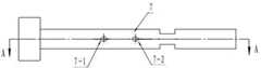
图1是本实用新型的结构示意图;Fig. 1 is the structural representation of the utility model;
图2是图1的左视图;Fig. 2 is the left view of Fig. 1;
图3是吸管的结构示意图(放大);Figure 3 is a schematic structural view of the straw (enlarged);
图4是图3的A-A剖视图。Fig. 4 is a cross-sectional view along line A-A of Fig. 3 .
图中各部件标号如下:1.储棉袋;2. 涡轮风机;3.储气罐;4.吹气主管;5.控制阀;6.吹气支管;7.吸管;7-1.第一进气孔;7-2.第二进气孔;7-3. 吸管出口;7-4.吸管进口,7-5.中间通道,8.尾纱管;9.纱管架;10.支架;11.抽气管。The labels of the components in the figure are as follows: 1. Cotton storage bag; 2. Turbine blower; 3. Air storage tank; 4. Blowing main pipe; One air inlet; 7-2. Second air inlet; 7-3. Suction pipe outlet; 7-4. Suction pipe inlet, 7-5. Middle channel, 8. Tail bobbin; 9. Bobbin frame; 10. Bracket; 11. Exhaust pipe.
具体实施方式Detailed ways
本实用新型具有双重打散尾纱的功能。参看图1、图2,所述打散装置包括支架10和依次相连的吸管7、抽气管11、涡轮风机2和储棉袋1。支架10中部设有纱管架9,尾纱管8位于纱管架上。吸管7固定在支架10的上部,吸管将吸入的尾纱经抽气管11送入涡轮风机2进行打散处理。为解决尾纱打散不彻底的问题,本实用新型还设有预打散结构,预打散结构包括储气罐3和与储气罐相连的吹气管。吹气管由吹气主管4和两根与吹气主管连通的吹气支管6组成,在吹气主管和吹气支管连接处设有控制气体流向的控制阀5。The utility model has the double function of loosening tail yarns. Referring to Fig. 1 and Fig. 2, the breaking up device includes a
参看图3、图4,本实用新型对吸管的结构进行了改进,吸管7设有中间通道7-5,在吸管中部设有与吸管中间通道连通的第一进气孔7-1和第二进气孔7-2,第一进气孔7-1、第二进气孔7-2倾斜设置,两个进气孔的倾斜方向相反,其中,第一进气孔7-1向吸管出口7-3的方向倾斜,所述第二进气孔7-2向吸管入口7-4的方向倾斜。两个进气孔的几何尺寸如下:第一进气孔7-1与吸管中间通道7-5的夹角为20°-60°,第二进气孔7-2与吸管中间通道的夹角为20°-60°,第一进气孔和第二进气孔的孔口间距L为10-100mm。打散装置工作时,两根吹气支管6的出口分别对应第一进气孔和第二进气孔。Referring to Fig. 3 and Fig. 4, the utility model has improved the structure of the suction pipe, the suction pipe 7 is provided with a middle passage 7-5, and the first air inlet 7-1 and the second air inlet connected with the middle passage of the suction pipe are arranged in the middle of the suction pipe. The air inlet 7-2, the first air inlet 7-1 and the second air inlet 7-2 are arranged obliquely, and the inclination directions of the two air inlets are opposite, wherein the first air inlet 7-1 faces the outlet of the straw 7-3 is inclined, and the second air inlet 7-2 is inclined toward the suction pipe inlet 7-4. The geometric dimensions of the two air inlets are as follows: the angle between the first air inlet 7-1 and the middle channel of the straw 7-5 is 20°-60°, the angle between the second air inlet 7-2 and the middle channel of the straw is 20°-60°, and the orifice spacing L between the first air inlet hole and the second air inlet hole is 10-100mm. When the dispersing device is working, the outlets of the two blowing branch pipes 6 correspond to the first air inlet and the second air inlet respectively.
仍参看图1、图2,本实用新型的工作过程如下:当尾纱管8上有尾纱时,尾纱被吸入吸管7,储气罐3通过吹气管向第一进气孔7-1提供高压压缩空气,将进入吸管内具有一定捻度的粗纱纱线进行高压吹打,进行预打散处理;涡轮风机2中的叶轮高速旋转,形成高负压,通过抽气管11将吸管内经过预打散的纱线吸入到涡轮风机腹腔,风机内高速旋转的叶轮将预打散的纱线进行第二次高负压打散,在双重打散作用下,粗纱纱线最终变成没有任何捻度和棉结的松散原棉;随后经过涡轮风机的排风口将松散原棉送入储棉袋1中。当尾纱管8上没有尾纱时,控制阀5切换,则储气罐经吹气管向第二进气孔7-2输入高压空气,将空管绒套上的飞花吹走。Still referring to Fig. 1, Fig. 2, the working process of the present utility model is as follows: when there is tail yarn on tail yarn tube 8, tail yarn is sucked into suction pipe 7, and air storage tank 3 blows to the first air inlet 7-1 through air blowing pipe. Provide high-pressure compressed air, blow the roving yarn with a certain twist into the suction pipe under high pressure, and perform pre-breaking treatment; The loose yarn is sucked into the abdominal cavity of the turbo blower, and the high-speed rotating impeller in the fan breaks the pre-break yarn under high negative pressure for the second time. Under the double break action, the roving yarn finally becomes without any twist and The loose raw cotton of neps; then the loose raw cotton is sent into the cotton storage bag 1 through the air outlet of the turbo blower. When there is no tail yarn on the tail yarn tube 8, the control valve 5 switches, and then the air storage tank imports high-pressure air to the second air inlet 7-2 through the air blowing pipe, and the flying flowers on the empty pipe velvet cover are blown away.
Claims (4)
Priority Applications (1)
| Application Number | Priority Date | Filing Date | Title |
|---|---|---|---|
| CN2013200436948UCN203144585U (en) | 2013-01-28 | 2013-01-28 | Scattering device for roving tail yarn treater |
Applications Claiming Priority (1)
| Application Number | Priority Date | Filing Date | Title |
|---|---|---|---|
| CN2013200436948UCN203144585U (en) | 2013-01-28 | 2013-01-28 | Scattering device for roving tail yarn treater |
Publications (1)
| Publication Number | Publication Date |
|---|---|
| CN203144585Utrue CN203144585U (en) | 2013-08-21 |
Family
ID=48972128
Family Applications (1)
| Application Number | Title | Priority Date | Filing Date |
|---|---|---|---|
| CN2013200436948UExpired - Fee RelatedCN203144585U (en) | 2013-01-28 | 2013-01-28 | Scattering device for roving tail yarn treater |
Country Status (1)
| Country | Link |
|---|---|
| CN (1) | CN203144585U (en) |
Cited By (4)
| Publication number | Priority date | Publication date | Assignee | Title |
|---|---|---|---|---|
| CN104803234A (en)* | 2015-04-22 | 2015-07-29 | 河北太行纺织机械有限公司 | Roving tail yarn removing machine |
| CN105236204A (en)* | 2015-11-09 | 2016-01-13 | 徐州天虹银丰纺织有限公司 | Automatic tail-blowing device |
| CN106809700A (en)* | 2017-03-28 | 2017-06-09 | 晋中华润机械制造有限公司 | A kind of new flyer bobbin tail yarn removes equipment |
| CN107006956A (en)* | 2017-04-27 | 2017-08-04 | 天津马士通机械设备有限公司 | A kind of outspoken fast cotton-filling machine of automatic shoe |
- 2013
- 2013-01-28CNCN2013200436948Upatent/CN203144585U/ennot_activeExpired - Fee Related
Cited By (5)
| Publication number | Priority date | Publication date | Assignee | Title |
|---|---|---|---|---|
| CN104803234A (en)* | 2015-04-22 | 2015-07-29 | 河北太行纺织机械有限公司 | Roving tail yarn removing machine |
| CN105236204A (en)* | 2015-11-09 | 2016-01-13 | 徐州天虹银丰纺织有限公司 | Automatic tail-blowing device |
| CN106809700A (en)* | 2017-03-28 | 2017-06-09 | 晋中华润机械制造有限公司 | A kind of new flyer bobbin tail yarn removes equipment |
| CN107006956A (en)* | 2017-04-27 | 2017-08-04 | 天津马士通机械设备有限公司 | A kind of outspoken fast cotton-filling machine of automatic shoe |
| CN107006956B (en)* | 2017-04-27 | 2022-03-18 | 马士通安全设备(天津)有限公司 | Automatic quick cotton filling machine for welt |
Similar Documents
| Publication | Publication Date | Title |
|---|---|---|
| CN203144585U (en) | Scattering device for roving tail yarn treater | |
| CN204509572U (en) | A kind of rotor spinning machine spinning device impurities removal anti-block apparatus | |
| CN205965326U (en) | Shearing machine dust collector | |
| CN204111063U (en) | Tail yarn end retaining device removed by a kind of tail yarn | |
| CN204298532U (en) | A kind of Speed frames | |
| CN204470207U (en) | Glass fabric surface dust cleaning apparatus | |
| CN203794334U (en) | Automatic winder suction nozzle of air-blowing obstacle removing structure | |
| CN203034167U (en) | Ultrahigh-molecular-weight polyethylene fiber waste silk recovery device | |
| CN205099833U (en) | Novel rotor type open -end spinning machine arranges miscellaneously device | |
| CN205546572U (en) | Take impurity removal function's defeated cotton transition device | |
| CN202347159U (en) | Faucet suction device of carding machine | |
| CN203212692U (en) | Middle noil suction device applicable to opening picking machine or blowing-carding process | |
| CN203999979U (en) | For the clean recovery unit of combing machine drafting roller | |
| CN201962444U (en) | Online impurity-picking device for opened and cleaned cotton | |
| CN103215694A (en) | Middle noil absorption device suitable for opening picking machinery or in blowing-carding process | |
| CN208201224U (en) | Itself the cleanable clear suede device of rove air sucking/blowing | |
| CN209541289U (en) | The good water scooping machine of drying effect | |
| CN207811964U (en) | A kind of carding machine wind-tone horn mouth spinning-in system | |
| CN105775917A (en) | Bobbin tail yarn clearing method | |
| CN204661919U (en) | A kind of suction yarn case except abnormal yarn | |
| CN203112997U (en) | Cleaning and air suction device for roving machine | |
| CN202643953U (en) | Dust removal device for cotton slitting machine | |
| CN201560265U (en) | Impurity suction and impurity collection device of rotating cup spinning machine | |
| CN204491113U (en) | Pneumatic lifting head device | |
| CN104176563A (en) | Tail yarn head keeping device for tail yarn removing machine |
Legal Events
| Date | Code | Title | Description |
|---|---|---|---|
| C14 | Grant of patent or utility model | ||
| GR01 | Patent grant | ||
| C41 | Transfer of patent application or patent right or utility model | ||
| TR01 | Transfer of patent right | Effective date of registration:20170103 Address after:052160 Hebei province Ganjiang Road, Shijiazhuang economic and Technological Development Zone No. 2 Patentee after:Hebei Taihang Textile Machinery Co., Ltd Address before:052160 Hebei province Ganjiang Road, Shijiazhuang economic and Technological Development Zone No. 2 Patentee before:Hebei Taihang Machinery Industries Co., Ltd. | |
| CF01 | Termination of patent right due to non-payment of annual fee | Granted publication date:20130821 Termination date:20170128 | |
| CF01 | Termination of patent right due to non-payment of annual fee |