CN203118978U - U-shaped pipe fin type dual-medium intensified radiation photovoltaic optothermal integrated device - Google Patents
U-shaped pipe fin type dual-medium intensified radiation photovoltaic optothermal integrated deviceDownload PDFInfo
- Publication number
- CN203118978U CN203118978UCN201320053260.6UCN201320053260UCN203118978UCN 203118978 UCN203118978 UCN 203118978UCN 201320053260 UCN201320053260 UCN 201320053260UCN 203118978 UCN203118978 UCN 203118978U
- Authority
- CN
- China
- Prior art keywords
- water
- flow channel
- heat
- shaped
- photovoltaic
- Prior art date
- Legal status (The legal status is an assumption and is not a legal conclusion. Google has not performed a legal analysis and makes no representation as to the accuracy of the status listed.)
- Expired - Fee Related
Links
- 230000005855radiationEffects0.000titleabstract2
- XLYOFNOQVPJJNP-UHFFFAOYSA-NwaterSubstancesOXLYOFNOQVPJJNP-UHFFFAOYSA-N0.000claimsabstractdescription39
- 239000002826coolantSubstances0.000claimsabstractdescription9
- 238000006243chemical reactionMethods0.000claimsabstractdescription8
- 229910021421monocrystalline siliconInorganic materials0.000claimsabstractdescription4
- 229910021420polycrystalline siliconInorganic materials0.000claimsabstractdescription4
- 230000017525heat dissipationEffects0.000claimsdescription11
- RYGMFSIKBFXOCR-UHFFFAOYSA-NCopperChemical compound[Cu]RYGMFSIKBFXOCR-UHFFFAOYSA-N0.000claimsdescription7
- 229910052802copperInorganic materials0.000claimsdescription7
- 239000010949copperSubstances0.000claimsdescription7
- 239000011521glassSubstances0.000claimsdescription7
- 238000009413insulationMethods0.000claimsdescription4
- 229910000838Al alloyInorganic materials0.000claimsdescription3
- 229920005830Polyurethane FoamPolymers0.000claimsdescription3
- 239000011496polyurethane foamSubstances0.000claimsdescription3
- 239000005341toughened glassSubstances0.000claimsdescription3
- 239000002994raw materialSubstances0.000claimsdescription2
- 238000010248power generationMethods0.000abstractdescription7
- 230000009977dual effectEffects0.000abstractdescription2
- 230000000694effectsEffects0.000description4
- 238000001816coolingMethods0.000description3
- 238000000034methodMethods0.000description2
- 239000011324beadSubstances0.000description1
- 230000009286beneficial effectEffects0.000description1
- 230000005540biological transmissionEffects0.000description1
- 239000000498cooling waterSubstances0.000description1
- 238000005260corrosionMethods0.000description1
- 238000010586diagramMethods0.000description1
- 230000005611electricityEffects0.000description1
- 238000005516engineering processMethods0.000description1
- 230000002708enhancing effectEffects0.000description1
- 230000005484gravityEffects0.000description1
- 238000010438heat treatmentMethods0.000description1
- 230000031700light absorptionEffects0.000description1
- 230000003647oxidationEffects0.000description1
- 238000007254oxidation reactionMethods0.000description1
- 230000005622photoelectricityEffects0.000description1
- 238000011426transformation methodMethods0.000description1
- 238000002834transmittanceMethods0.000description1
Images


Classifications
- Y—GENERAL TAGGING OF NEW TECHNOLOGICAL DEVELOPMENTS; GENERAL TAGGING OF CROSS-SECTIONAL TECHNOLOGIES SPANNING OVER SEVERAL SECTIONS OF THE IPC; TECHNICAL SUBJECTS COVERED BY FORMER USPC CROSS-REFERENCE ART COLLECTIONS [XRACs] AND DIGESTS
- Y02—TECHNOLOGIES OR APPLICATIONS FOR MITIGATION OR ADAPTATION AGAINST CLIMATE CHANGE
- Y02E—REDUCTION OF GREENHOUSE GAS [GHG] EMISSIONS, RELATED TO ENERGY GENERATION, TRANSMISSION OR DISTRIBUTION
- Y02E10/00—Energy generation through renewable energy sources
- Y02E10/50—Photovoltaic [PV] energy
Landscapes
- Photovoltaic Devices (AREA)
Abstract
Description
Translated fromChinese技术领域technical field
本实用新型涉及一种U型管翅片式双介质强化散热光伏光热一体化装置,属于太阳能光电,光热技术领域。The utility model relates to a U-shaped tube fin type dual-medium enhanced heat dissipation photovoltaic photothermal integrated device, which belongs to the technical fields of solar photoelectricity and photothermal technology.
背景技术Background technique
太阳能光电/光热综合利用系统是将太阳能电池(或组件)与太阳能集热器结合起来制造而成的具有发电以及供热功能的一种装置,我们也可称之为光伏光热一体化系统(PVT)。这种系统的优势在于既能解决因光伏电池板(或组件)温度过高导致发电效率降低的问题,同时又能将电池板的一部分热量加以利用,为用户提供热水或供暖等。The solar photoelectric/photothermal comprehensive utilization system is a device that combines solar cells (or components) and solar collectors to produce power generation and heat supply functions. We can also call it a photovoltaic photothermal integrated system. (PVT). The advantage of this system is that it can not only solve the problem of low power generation efficiency due to high temperature of photovoltaic panels (or components), but also utilize part of the heat of the panels to provide users with hot water or heating.
目前的光伏光热一体化系统多是采用单一冷却介质,如空气或水。空气冷却型模式构造简单,但冷却效果不理想,而且无法利用到太阳能光伏电池模块产生的热量;水冷却型模式结构较为复杂,但冷却效果优于空气冷却型模式,同时利用了光伏模块产生的热量,提高了太阳能的综合利用效率。Most of the current photovoltaic-thermal integrated systems use a single cooling medium, such as air or water. The structure of the air-cooled model is simple, but the cooling effect is not ideal, and the heat generated by the solar photovoltaic cell module cannot be used; the structure of the water-cooled model is more complicated, but the cooling effect is better than that of the air-cooled model, and at the same time, the heat generated by the photovoltaic module is used. heat, improving the comprehensive utilization efficiency of solar energy.
增强太阳能光伏电池模块的散热进而提高发电效率是光伏光热一体化系统的首要任务,也是这一系统的重要研究方向。Enhancing the heat dissipation of solar photovoltaic cell modules to improve power generation efficiency is the primary task of the photovoltaic-thermal integrated system, and it is also an important research direction of this system.
实用新型内容Utility model content
本实用新型的目的在于提供一种提高太阳能综合利用效率的光伏光热一体化装置。The purpose of the utility model is to provide a photovoltaic photothermal integrated device that improves the comprehensive utilization efficiency of solar energy.
本实用新型是通过如下的技术方案来实现:The utility model is realized through the following technical solutions:
一种U型管翅片式双介质强化散热光伏光热一体化装置,包括光电转换装置和冷却介质流道装置,所述光电转换装置采用单晶硅或多晶硅太阳能电池板,将太阳能转换为电能,为用户供电;所述太阳能电池板的上面覆盖玻璃盖板;所述冷却介质流道装置包括U型管水流道和U型空气流道,所述U型管水流道的水管采用横向分布,与太阳能电池板背紧密结合,布满整个电池板背;所述U型管水流道的下部设有进水口,通过管道与水泵相连,上部设有出水口,接入热用户;所述U型空气流道分为上下两层,上层流道由玻璃盖板和太阳能电池板构成,下层流道由U型管水流道和吸热板构成,所述吸热板的纵向布满翅片,吸热板通过导热板与太阳能电池板相连;所述上层流道设有进气口,通过管道与风机相连,所述下层流道设有出气口。A U-shaped tube-fin dual-medium enhanced heat dissipation photovoltaic photothermal integrated device, including a photoelectric conversion device and a cooling medium flow channel device, the photoelectric conversion device uses monocrystalline silicon or polycrystalline silicon solar panels to convert solar energy into electrical energy , to supply power for users; the solar panel is covered with a glass cover plate; the cooling medium flow channel device includes a U-shaped water flow channel and a U-shaped air flow channel, and the water pipes of the U-shaped water flow channel are distributed horizontally, It is closely combined with the back of the solar panel and covers the entire back of the panel; the lower part of the U-shaped pipe water flow channel is provided with a water inlet, which is connected to the water pump through a pipe, and the upper part is provided with a water outlet to connect to the heat user; The air flow channel is divided into upper and lower layers. The upper flow channel is composed of a glass cover plate and a solar panel, and the lower flow channel is composed of a U-shaped pipe water flow channel and a heat-absorbing plate. The longitudinal direction of the heat-absorbing plate is covered with fins. The heat plate is connected with the solar panel through the heat conduction plate; the upper flow channel is provided with an air inlet, and is connected with the fan through a pipe; the lower flow channel is provided with an air outlet.
前述U型管水流道的水管采用铜作为原材料。The water pipe of the aforementioned U-shaped pipe water channel adopts copper as a raw material.
前述玻璃盖板为高透光的钢化玻璃。The aforementioned glass cover plate is tempered glass with high light transmission.
前述吸热板的底面有聚氨酯发泡绝热层。The bottom surface of the aforementioned heat absorbing board has a polyurethane foam heat insulating layer.
前述装置四周和吸热板底面绝热层用铝合金框密封。The heat insulation layer around the aforementioned device and the bottom surface of the heat-absorbing plate is sealed with an aluminum alloy frame.
采用上述技术手段,本实用新型具有的有益效果为:利用水和空气双重介质进行换热,强化了冷却效果,有效降低光伏电池组件温度;采用U型水管的结构,既能对电池板冷却,提高其发电效率,同时自身的温度升高,可将热水引入热用户,提高太阳能综合利用效率;采用翅片结构,增大了换热面积,可以促进电池板的散热。By adopting the above-mentioned technical means, the beneficial effects of the utility model are as follows: the dual media of water and air are used for heat exchange, the cooling effect is strengthened, and the temperature of the photovoltaic battery module is effectively reduced; the structure of the U-shaped water pipe is adopted, which can not only cool the battery board, Improve its power generation efficiency, while its own temperature rises, hot water can be introduced into heat users, and the comprehensive utilization efficiency of solar energy is improved; the fin structure is adopted to increase the heat exchange area, which can promote the heat dissipation of the battery panel.
附图说明Description of drawings
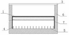
图1为本实用新型的U型管水流道示意图;Fig. 1 is a schematic diagram of a U-shaped pipe water channel of the present invention;
图2为本实用新型的U型空气流道侧视图;Fig. 2 is a side view of the U-shaped air channel of the present invention;
图3为本实用新型的U型空气流道主视图。Fig. 3 is a front view of the U-shaped air channel of the present invention.
具体实施方式Detailed ways
下面结合附图具体实施方式,对本实用新型进行进一步的阐述。The utility model is further elaborated below in conjunction with the specific embodiments of the accompanying drawings.
本实用新型的U型管翅片式双介质强化散热光伏光热一体化装置,包括光电转换装置和冷却介质流道装置,光电转换装置即为单晶硅或多晶硅太阳能电池板,它利用“光伏效应”将太阳能转换为电能,为用户供电。太阳能电池板的上面覆盖有高透光钢化玻璃盖板,既能保证太阳能电池板对光的吸收,又能保护太阳能电池板免受雨雪,高温等外界恶劣天气的损坏。The U-shaped tube-fin type dual-medium enhanced heat dissipation photovoltaic photothermal integrated device of the present invention includes a photoelectric conversion device and a cooling medium flow channel device. The photoelectric conversion device is a monocrystalline silicon or polycrystalline silicon solar cell panel. Effect" converts solar energy into electricity to power users. The top of the solar panel is covered with a high-transmittance tempered glass cover, which can not only ensure the absorption of light by the solar panel, but also protect the solar panel from rain, snow, high temperature and other bad weather.
冷却介质流道装置包括U型管水流道和U型空气流道,如图1所示,U型管水流道的水管以具有良好导热性能的铜作为原材料,采用横向布置的方式,可以降低水泵在输水过程中需克服水的重力及流动阻力而消耗的电能,水管的有效直径和壁厚根据电池板面积、进出水温度、水流量等确定。本实用新型用压条将所述U型铜管2与太阳能电池板1的背面紧密结合,U型铜管2布满整个电池板背,增大了传热面积。U型铜管2的下部设有进水口,上部设有出水口,进水口通过管道与水泵相连,冷却水在水泵的驱动下流经U型管水流道,冷却太阳能电池板1,提高其发电效率,同时自身的温度升高,从出水口引入热用户。The cooling medium flow channel device includes a U-shaped pipe water flow channel and a U-shaped air flow channel. As shown in Figure 1, the water pipes of the U-shaped water flow channel are made of copper with good thermal conductivity. In the process of water delivery, it is necessary to overcome the gravity of water and the power consumed by the flow resistance. The effective diameter and wall thickness of the water pipe are determined according to the area of the battery plate, the temperature of the incoming and outgoing water, and the flow of water. The utility model tightly combines the U-shaped
如图2和图3所示,U型空气流道分为上下两层,上层流道由玻璃盖板3和太阳能电池板1构成,下层流道由U型管水流道和纵向布满翅片4的吸热板5构成,吸热板5通过导热板7与太阳能电池板1相连,翅片4结构增大了换热面积,可以促进太阳能电池板1的散热。U型空气流道上层设有进气口,下层设有出气口,进气口通过管道与风机相连,空气在风机的驱动下流经整个U型空气流道,依次吸收来自电池板正面、电池板背面以及吸热板5、导热板7的热能,并促进电池板背与U型铜管2的热交换,从而进一步降低电池板的温度,提高其发电效率。As shown in Figure 2 and Figure 3, the U-shaped air flow channel is divided into upper and lower layers, the upper flow channel is composed of
吸热板的底面有聚氨酯发泡绝热层,最后装置四周和吸热板底面绝热层用铝合金边框6密封,具有良好的抗腐蚀和抗氧化性能且牢固,有效地延长太阳能电池板在户外的使用寿命。The bottom of the heat-absorbing plate has a polyurethane foam insulation layer, and finally the surroundings of the device and the heat-insulating layer on the bottom of the heat-absorbing plate are sealed with an
以上已以较佳实施例公开了本实用新型,然其并非用以限制本实用新型,凡采用等同替换或者等效变换方式所获得的技术方案,均落在本实用新型的保护范围之内。The utility model has been disclosed above with preferred embodiments, but it is not intended to limit the utility model, and all technical solutions obtained by adopting equivalent replacement or equivalent transformation methods fall within the protection scope of the utility model.
Claims (5)
Translated fromChinesePriority Applications (1)
| Application Number | Priority Date | Filing Date | Title |
|---|---|---|---|
| CN201320053260.6UCN203118978U (en) | 2013-01-30 | 2013-01-30 | U-shaped pipe fin type dual-medium intensified radiation photovoltaic optothermal integrated device |
Applications Claiming Priority (1)
| Application Number | Priority Date | Filing Date | Title |
|---|---|---|---|
| CN201320053260.6UCN203118978U (en) | 2013-01-30 | 2013-01-30 | U-shaped pipe fin type dual-medium intensified radiation photovoltaic optothermal integrated device |
Publications (1)
| Publication Number | Publication Date |
|---|---|
| CN203118978Utrue CN203118978U (en) | 2013-08-07 |
Family
ID=48899297
Family Applications (1)
| Application Number | Title | Priority Date | Filing Date |
|---|---|---|---|
| CN201320053260.6UExpired - Fee RelatedCN203118978U (en) | 2013-01-30 | 2013-01-30 | U-shaped pipe fin type dual-medium intensified radiation photovoltaic optothermal integrated device |
Country Status (1)
| Country | Link |
|---|---|
| CN (1) | CN203118978U (en) |
Cited By (3)
| Publication number | Priority date | Publication date | Assignee | Title |
|---|---|---|---|---|
| CN105356846A (en)* | 2015-11-20 | 2016-02-24 | 上海应用技术学院 | Novel photovoltaic photo-thermal integrated assembly |
| CN105605798A (en)* | 2014-08-08 | 2016-05-25 | 北京建筑大学 | Vacuum-tube solar thermal collector and heat pump system |
| CN105978482A (en)* | 2016-07-08 | 2016-09-28 | 河海大学常州校区 | Novel air-cooled PV/T system based on improvement of solar photovoltaic thermal efficiency |
- 2013
- 2013-01-30CNCN201320053260.6Upatent/CN203118978U/ennot_activeExpired - Fee Related
Cited By (4)
| Publication number | Priority date | Publication date | Assignee | Title |
|---|---|---|---|---|
| CN105605798A (en)* | 2014-08-08 | 2016-05-25 | 北京建筑大学 | Vacuum-tube solar thermal collector and heat pump system |
| CN105356846A (en)* | 2015-11-20 | 2016-02-24 | 上海应用技术学院 | Novel photovoltaic photo-thermal integrated assembly |
| CN105356846B (en)* | 2015-11-20 | 2017-05-17 | 上海应用技术大学 | Photovoltaic photo-thermal integrated assembly |
| CN105978482A (en)* | 2016-07-08 | 2016-09-28 | 河海大学常州校区 | Novel air-cooled PV/T system based on improvement of solar photovoltaic thermal efficiency |
Similar Documents
| Publication | Publication Date | Title |
|---|---|---|
| CN102487255B (en) | Solar energy composite utilizes device | |
| CN202025783U (en) | Solar photovoltaic thermoelectric heating module and photovoltaic thermoelectric hot water system | |
| CN103398474B (en) | Solar photovoltaic-photothermal-thermoelectric comprehensive utilization system | |
| CN105553408B (en) | A kind of absorber plate photovoltaic and photothermal solar integrated module compound directly with glass cover-plate | |
| CN201570507U (en) | Solar-energy electric heating integration assembly | |
| CN102052782A (en) | Heat-pipe type solar energy photoelectric and optothermal comprehensive utilization system | |
| CN102563891A (en) | Capillary tube radiation cooling type photovoltaic electricity and heat combined using device | |
| CN102270689A (en) | Electrothermal cogeneration cell panel for photovoltaic curtain walls | |
| CN103062913A (en) | Flat-panel solar photovoltaic water-heating air-heating compound heat collector | |
| CN107623048A (en) | A solar photovoltaic photothermal comprehensive utilization device | |
| CN204460773U (en) | A kind of electron tubes type photovoltaic and photothermal solar integral component | |
| CN102607206B (en) | Solar photovoltaic photo-thermal composite heat pipe vacuum tube | |
| CN203339200U (en) | Heat collector of a solar energy comprehensive utilization system | |
| CN203118978U (en) | U-shaped pipe fin type dual-medium intensified radiation photovoltaic optothermal integrated device | |
| CN104935239A (en) | A new type of solar photovoltaic photothermal integrated device | |
| CN201616447U (en) | Solar electric heating integrated components | |
| CN203454422U (en) | Air liquid type photovoltaic and photo-thermal heat exchange system | |
| CN105978482A (en) | Novel air-cooled PV/T system based on improvement of solar photovoltaic thermal efficiency | |
| CN100424893C (en) | Combined electricity and heat device for solar cells | |
| CN205944108U (en) | Adopt gravity heat pipe to reinforce photovoltaic module of heat transfer | |
| CN101800258A (en) | Electricity-heat-cold triplex co-generation building integrated radiation panel | |
| CN219018772U (en) | Photovoltaic module, heat dissipation device thereof and photovoltaic system | |
| CN203840255U (en) | Split balcony wall-mounted solar photovoltaic photothermal integrated system | |
| CN217299536U (en) | A dual-fluid photovoltaic photothermal roof assembly for residential buildings | |
| CN207083059U (en) | A kind of modified high temperature resistant solar panel |
Legal Events
| Date | Code | Title | Description |
|---|---|---|---|
| C14 | Grant of patent or utility model | ||
| GR01 | Patent grant | ||
| CF01 | Termination of patent right due to non-payment of annual fee | Granted publication date:20130807 Termination date:20160130 | |
| EXPY | Termination of patent right or utility model |