CN203053481U - Wireless energy efficiency testing system of refrigerator based on ZigBee technology - Google Patents
Wireless energy efficiency testing system of refrigerator based on ZigBee technologyDownload PDFInfo
- Publication number
- CN203053481U CN203053481UCN2013200277462UCN201320027746UCN203053481UCN 203053481 UCN203053481 UCN 203053481UCN 2013200277462 UCN2013200277462 UCN 2013200277462UCN 201320027746 UCN201320027746 UCN 201320027746UCN 203053481 UCN203053481 UCN 203053481U
- Authority
- CN
- China
- Prior art keywords
- wireless
- node
- temperature
- acquisition
- routing node
- Prior art date
- Legal status (The legal status is an assumption and is not a legal conclusion. Google has not performed a legal analysis and makes no representation as to the accuracy of the status listed.)
- Expired - Fee Related
Links
- 238000012360testing methodMethods0.000titleclaimsabstractdescription24
- 238000005516engineering processMethods0.000titleclaimsabstractdescription12
- 238000001514detection methodMethods0.000claimsabstractdescription20
- 239000004973liquid crystal related substanceSubstances0.000claimsdescription6
- 238000007689inspectionMethods0.000abstract2
- 230000007613environmental effectEffects0.000abstract1
- 238000004891communicationMethods0.000description7
- 238000000034methodMethods0.000description6
- 230000006870functionEffects0.000description5
- 238000009529body temperature measurementMethods0.000description4
- 238000010586diagramMethods0.000description4
- 238000005259measurementMethods0.000description4
- 238000012545processingMethods0.000description3
- 238000009434installationMethods0.000description2
- 238000012423maintenanceMethods0.000description2
- 238000012544monitoring processMethods0.000description2
- 230000006855networkingEffects0.000description2
- 230000009286beneficial effectEffects0.000description1
- 230000005540biological transmissionEffects0.000description1
- 238000001816coolingMethods0.000description1
- 238000012937correctionMethods0.000description1
- 230000007812deficiencyEffects0.000description1
- 238000011161developmentMethods0.000description1
- 230000002093peripheral effectEffects0.000description1
- 238000011076safety testMethods0.000description1
- 239000004065semiconductorSubstances0.000description1
Images


Classifications
- Y—GENERAL TAGGING OF NEW TECHNOLOGICAL DEVELOPMENTS; GENERAL TAGGING OF CROSS-SECTIONAL TECHNOLOGIES SPANNING OVER SEVERAL SECTIONS OF THE IPC; TECHNICAL SUBJECTS COVERED BY FORMER USPC CROSS-REFERENCE ART COLLECTIONS [XRACs] AND DIGESTS
- Y02—TECHNOLOGIES OR APPLICATIONS FOR MITIGATION OR ADAPTATION AGAINST CLIMATE CHANGE
- Y02D—CLIMATE CHANGE MITIGATION TECHNOLOGIES IN INFORMATION AND COMMUNICATION TECHNOLOGIES [ICT], I.E. INFORMATION AND COMMUNICATION TECHNOLOGIES AIMING AT THE REDUCTION OF THEIR OWN ENERGY USE
- Y02D30/00—Reducing energy consumption in communication networks
- Y02D30/70—Reducing energy consumption in communication networks in wireless communication networks
Landscapes
- Arrangements For Transmission Of Measured Signals (AREA)
Abstract
Translated fromChinese
Description
Translated fromChinese技术领域technical field
本实用新型涉及一种能效测试系统,特别涉及一种基于ZigBee技术的电冰箱无线能效测试系统。The utility model relates to an energy efficiency testing system, in particular to a wireless energy efficiency testing system for a refrigerator based on ZigBee technology.
背景技术Background technique
现阶段家用电器检测过程中,基本都是以有线的方式进行连接,例如安全试验中的输入功率和输入电流测量、温升试验的温度记录等,型式试验中储藏温度、冷却速度等项目的检测,能效试验中耗电量、热效率等项目的检测。有线连接的检测方法对于基本固定的被测对象来说是比较理想的选择,且在实际使用中达到满意的效果。但随着无线技术的发展,无线通讯功能的实现越来越简单,而且数据传输速度也越来越快,完全可以达到有线通信的水平。同时有线连接布线麻烦,线路故障难以检查,且不可随意移动。At present, in the testing process of household appliances, they are basically connected in a wired way, such as the input power and input current measurement in the safety test, the temperature record in the temperature rise test, etc., and the detection of storage temperature, cooling speed and other items in the type test. , Detection of power consumption, thermal efficiency and other items in the energy efficiency test. The detection method of wired connection is an ideal choice for the basically fixed measured object, and achieves satisfactory results in actual use. However, with the development of wireless technology, the realization of wireless communication functions is becoming more and more simple, and the data transmission speed is getting faster and faster, which can completely reach the level of wired communication. At the same time, wired connection and wiring are troublesome, and line faults are difficult to check, and they cannot be moved at will.
中国发明专利公开号CN201819704,公开日2011年5月4日,专利名称为《基于微功率无线通信技术的电冰箱能效试验》,该专利公开了一种运用微功率无线通信技术,利用半导体传感器LM92和无线单片机CC1110设计了一套无线测温系统,从而减少线路质量对测试结果的影响,而且降低维护难度,提高检测工作效率,降低了测量误差,保证了检测数据的准确性。该系统的不足之处在于:该系统仅实现了无线测温,而能效试验中的电参数测量依然采用有线方式,依然存在布线麻烦的问题,而且电冰箱能效试验主要测试项目为耗电量,耗电量结果的准确性直接影响电冰箱能效测试结果的准确度。Chinese Invention Patent Publication No. CN201819704, published on May 4, 2011, the patent name is "Refrigerator Energy Efficiency Test Based on Micro-power Wireless Communication Technology", the patent discloses a micro-power wireless communication technology, using semiconductor sensor LM92 A set of wireless temperature measurement system was designed with the wireless microcontroller CC1110, so as to reduce the influence of line quality on test results, reduce maintenance difficulty, improve detection efficiency, reduce measurement errors, and ensure the accuracy of detection data. The disadvantages of this system are: the system only realizes wireless temperature measurement, while the electrical parameter measurement in the energy efficiency test still adopts the wired method, and there is still the problem of troublesome wiring, and the main test item of the energy efficiency test of the refrigerator is power consumption. The accuracy of power consumption results directly affects the accuracy of refrigerator energy efficiency test results.
发明内容Contents of the invention
本实用新型的目的在于提供一种基于ZigBee技术的电冰箱无线能效测试系统, 解决有线检测存在的布线麻烦、成本高的问题,而且本系统不仅可以无线测温,而且还可以无线测量电参数,弥补现有冰箱能效测试系统的不足。The purpose of this utility model is to provide a wireless energy efficiency test system for refrigerators based on ZigBee technology, which solves the problems of troublesome wiring and high cost in wired detection, and this system can not only measure temperature wirelessly, but also measure electrical parameters wirelessly, Make up for the deficiencies of the existing refrigerator energy efficiency testing system.
为解决上述技术问题,本实用新型通过以下技术方案实现:In order to solve the above technical problems, the utility model is realized through the following technical solutions:
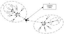
本实用新型包括至少一个电参数无线采集节点、至少两个温度无线采集节点、至少一个用于管理温度无线采集节点并兼具中继功能的温度无线路由节点、至少一个用于管理电参数无线采集节点并兼具中继功能的电参数无线路由节点、一个用于收集数据的协调器节点和一台计算机;其中,The utility model comprises at least one electric parameter wireless collection node, at least two temperature wireless collection nodes, at least one temperature wireless routing node used for managing the temperature wireless collection node and having a relay function, at least one used for managing the electric parameter wireless collection node node and a wireless routing node of electrical parameters with relay function, a coordinator node for collecting data and a computer; among them,
1)电参数无线采集节点中的一个发射模块、分别通过导线和一个电参数采集模块、第一个RF天线、一个液晶显示电路相连;1) A transmitting module in the electrical parameter wireless acquisition node is connected to an electrical parameter acquisition module, the first RF antenna, and a liquid crystal display circuit through wires;
2)温度无线采集节点中的一个发射模块分别通过导线至少一个温度采集模块、第二个RF天线、一个液晶显示电路相连;2) A transmitter module in the temperature wireless acquisition node is connected to at least one temperature acquisition module, the second RF antenna, and a liquid crystal display circuit through wires;
3)温度无线路由节点中的一个发射模块通过导线和第三个RF天线相连;3) A transmitting module in the temperature wireless routing node is connected to the third RF antenna through a wire;
4)电参数无线路由节点中的一个发射模块通过导线和第四个RF天线相连;4) A transmitting module in the electrical parameter wireless routing node is connected to the fourth RF antenna through wires;
5)协调器节点中的一个发射模块分别和第五个RF天线、一个串口电路相连;5) A transmitting module in the coordinator node is connected to the fifth RF antenna and a serial port circuit respectively;
6)电参数无线采集节点通过无线网络和电参数无线路由节点进行连接,温度无线采集节点通过无线网络和温度无线路由节点进行连接,温度无线路由节点和电参数无线路由节点分别通过无线网络和协调器节点连接,协调器节点和计算机通过串口线相连。6) The electrical parameter wireless collection node is connected through the wireless network and the electrical parameter wireless routing node. The coordinator node is connected to the coordinator node and the computer through a serial cable.
所述的所有发射模块均为无线收发器CC2430;所述的温度采集模块为DS18B20温度传感器;所述的电参数采集模块包括ADE7755电能计量芯片、电压检测电路和电流检测电路;其中,电压检测电路和电流检测电路分别通过导线和ADE7755电能计量芯片相连。All described transmitting modules are wireless transceivers CC2430; the described temperature acquisition module is a DS18B20 temperature sensor; the described electrical parameter acquisition module includes an ADE7755 electric energy metering chip, a voltage detection circuit and a current detection circuit; wherein, the voltage detection circuit It is connected with the current detection circuit and the ADE7755 electric energy measurement chip through wires respectively.
本实用新型具有的有益效果是:The beneficial effect that the utility model has is:
本实用新型借助无线通讯技术ZigBee技术自组网、低成本、自组织、低功耗的特点,实现了电冰箱无线能效测试,避免了传统布线时采集点布置困难、系统成本高、安装维护难度大的缺点,系统配置简单,安装灵活,解决了有线检测存在的布线麻烦、成本高等问题,而且本系统不仅可以无线测温,而且还可以无线测量电参数,实现真正的电冰箱无线能效测试。The utility model realizes the wireless energy efficiency test of the refrigerator with the help of the wireless communication technology ZigBee technology self-organizing network, low cost, self-organization and low power consumption, and avoids the difficulty of collecting point layout, high system cost and difficulty of installation and maintenance during traditional wiring. The biggest disadvantage is that the system configuration is simple and the installation is flexible, which solves the problems of troublesome wiring and high cost in wired detection. Moreover, this system can not only measure temperature wirelessly, but also measure electrical parameters wirelessly, realizing the real wireless energy efficiency test of refrigerators.
附图说明Description of drawings
图1是本实用新型的系统结构框图。Fig. 1 is a system structure diagram of the utility model.
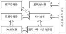
图2是本实用新型的发射模块CC2430芯片的内部结构框图。Fig. 2 is a block diagram of the internal structure of the transmitting module CC2430 chip of the present invention.
图3是本实用新型的温度无线采集节点硬件结构图。Fig. 3 is a hardware structural diagram of the temperature wireless acquisition node of the present invention.
图4是本实用新型的电参数无线采集节点硬件结构图。Fig. 4 is a hardware structure diagram of the electric parameter wireless collection node of the present invention.
图5是本实用新型的协调器节点软件流程图。Fig. 5 is a flow chart of the coordinator node software of the present invention.
图6是本实用新型的温度无线路由节点软件流程图。Fig. 6 is a flow chart of the temperature wireless routing node software of the present invention.
图7是本实用新型的温度无线采集节点软件流程图。Fig. 7 is a software flowchart of the temperature wireless acquisition node of the present invention.
图中:1、温度采集模块;2、电参数采集模块;3、发射模块;4、电参数无线采集节点;5、温度无线采集节点6、温度无线路由节点;7、电参数无线路由节点;8、协调器节点;9、计算机。In the figure: 1. Temperature acquisition module; 2. Electrical parameter acquisition module; 3. Transmitting module; 4. Electrical parameter wireless acquisition node; 5. Temperature wireless acquisition node 6. Temperature wireless routing node; 7. Electrical parameter wireless routing node; 8. Coordinator node; 9. Computer.
具体实施方式Detailed ways
下面结合附图和实施例对本实用新型作进一步的说明。Below in conjunction with accompanying drawing and embodiment the utility model is described further.
如图1所示,一种基于ZigBee技术的电冰箱无线能效测试系统,包括五个电参数无线采集节点4、五个温度无线采集节点5、一个用于管理温度无线采集节点并兼具中继功能的温度无线路由节点6、一个用于管理电参数无线采集节点并兼具中继功能的电参数无线路由节点7、一个用于收集数据的协调器节点8和一台计算机9。其中,电参数无线采集节点通过无线网络和电参数无线路由节点7进行连接,温度无线采集节点5通过无线网络和温度无线路由节点6进行连接,温度无线路由节点6和电参数无线路由节点7分别通过无线网络和协调器节点8连接,协调器节点8和计算机9通过串口线相连。如果温度无线路由节点6和电参数无线路由节点7距离协调器节点8的距离超过ZigBee通信的距离,可以间接通过临近的路由器节点和协调器节点8通讯。As shown in Figure 1, a wireless energy efficiency test system for refrigerators based on ZigBee technology includes five wireless acquisition nodes 4 for electrical parameters, five wireless acquisition nodes 5 for temperature, and one wireless acquisition node for managing temperature and also has a relay Functional temperature wireless routing node 6, an electrical parameter wireless routing node 7 for managing electrical parameter wireless collection nodes and also having a relay function, a
如图2所示,发射模块3内部包括8051内核、程序存储器、射频控制电路、定时器电路、数据存储器、DMA控制器和通用IO端口/片内外设。其中8051内核为高性能和低功耗的增强型微控制器内核,运行时钟32MHz,具有8倍于标准8051内核性能。CC2430芯片还包括2.4GHz的RF收发器、4个频率可选择的振荡器。本实用新型中的协调器节点、温度无线路由节点、电参数无线路由节点、温度无线采集节点和电参数无线采集节点中的发射模块均为CC2430芯片,而且CC2430芯片可以很容易在市场上买到。As shown in FIG. 2 , the transmitting module 3 includes an 8051 core, a program memory, a radio frequency control circuit, a timer circuit, a data memory, a DMA controller, and general-purpose IO ports/chip peripherals. Among them, the 8051 core is an enhanced microcontroller core with high performance and low power consumption, and the running clock is 32MHz, which has 8 times the performance of the standard 8051 core. The CC2430 chip also includes a 2.4GHz RF transceiver and 4 frequency-selectable oscillators. The transmitter modules in the coordinator node, temperature wireless routing node, electrical parameter wireless routing node, temperature wireless acquisition node and electrical parameter wireless acquisition node in the utility model are all CC2430 chips, and the CC2430 chip can be easily purchased in the market .
如图3所示,温度无线采集节点5中的一个发射模块3分别通过导线和至少一个温度采集模块1、一个RF天线、一个液晶显示电路相连。温度采集模块1负责采集温度参数,发射模块3负责运行ZigBee协议并对温度数据进行处理、传输以及监控温度传感器的运行。温度采集模块1工作电压范围为3.0~5.5V,测温范围-55~125℃,固有测温分辨率为0.5℃,修正后可以达到±0.3℃。温度采集模块1的数据线引脚(DQ)和CC2430芯片任一个数字I/O引脚相连,工作时,需接一个上拉电阻为数据线提供能量,保证工作稳定。冰箱的每个间室放置一个温度无线采集节点5和若干个温度采集模块1,冰箱环境试验室放置若干个温度无线采集节点5。As shown in FIG. 3 , a transmitter module 3 in the temperature wireless acquisition node 5 is connected to at least one temperature acquisition module 1 , an RF antenna, and a liquid crystal display circuit through wires. The temperature acquisition module 1 is responsible for collecting temperature parameters, and the transmitting module 3 is responsible for running the ZigBee protocol, processing and transmitting temperature data, and monitoring the operation of the temperature sensor. The operating voltage range of the temperature acquisition module 1 is 3.0~5.5V, the temperature measurement range is -55~125°C, and the inherent temperature measurement resolution is 0.5°C, which can reach ±0.3°C after correction. The data line pin (DQ) of the temperature acquisition module 1 is connected to any digital I/O pin of the CC2430 chip. When working, a pull-up resistor needs to be connected to provide energy for the data line to ensure stable operation. A temperature wireless collection node 5 and several temperature collection modules 1 are placed in each compartment of the refrigerator, and several temperature wireless collection nodes 5 are placed in the refrigerator environment test room.
如图4所示,电参数无线采集节点4中的一个发射模块3分别通过导线和一个电参数采集模块2、一个RF天线、一个液晶显示电路相连,其中,电参数采集模块2包括电压检测电路、电流检测电路和ADE7755电能计量芯片。发射模块3负责运行ZigBee协议并对电参数数据进行处理、传输以及监控ADE7755芯片的运行。ADE7755芯片以预定的通信规约与发射模块3通信,提供相关电能参数(电压、电流、功率、电能等)。每个冰箱外放置一个电参数无线采集节点4。As shown in Figure 4, a transmitting module 3 in the electrical parameter wireless acquisition node 4 is connected to an electrical parameter acquisition module 2, an RF antenna, and a liquid crystal display circuit through wires, wherein the electrical parameter acquisition module 2 includes a voltage detection circuit , Current detection circuit and ADE7755 energy metering chip. The transmitting module 3 is responsible for running the ZigBee protocol, processing and transmitting the electrical parameter data and monitoring the operation of the ADE7755 chip. The ADE7755 chip communicates with the transmitting module 3 through a predetermined communication protocol, and provides relevant electric energy parameters (voltage, current, power, electric energy, etc.). An electrical parameter wireless collection node 4 is placed outside each refrigerator.
如图5、图6、图7所示,ZigBee协议组网过程为协调器节点8上电后,发出组网指令,建立以协调器节点8为中心的近距离网络,随后打开温度无线路由节点6和电参数无线路由节点7,路由节点加入到网络中,实现对网络覆盖范围的扩展,最后打开温度无线采集节点5和电参数无线采集节点4。如图5所示,协调器节点8作为中心控制平台,其任务首先建立新的网络,完成组建网络的工作,接收各网络节点发送的数据,对数据进行处理,并发送相应的控制信号。如图6所示,温度无线路由节点6负责查找目标设备即温度无线采集节点5,并接收温度无线采集节点的数据,并将数据处理后传送给协调器节点8,电参数无线路由节点的软件流程和温度无线路由节点的类似。如图7所示,温度无线采集节点5主要功能是加入ZigBee网络、读/写温度数据,收发ZigBee网络中的数据及命令,并根据命令操作采集模块。电参数无线采集节点的软件流程和温度无线采集节点类似。As shown in Figure 5, Figure 6, and Figure 7, the ZigBee protocol networking process is that after the
Claims (2)
Priority Applications (1)
| Application Number | Priority Date | Filing Date | Title |
|---|---|---|---|
| CN2013200277462UCN203053481U (en) | 2013-01-18 | 2013-01-18 | Wireless energy efficiency testing system of refrigerator based on ZigBee technology |
Applications Claiming Priority (1)
| Application Number | Priority Date | Filing Date | Title |
|---|---|---|---|
| CN2013200277462UCN203053481U (en) | 2013-01-18 | 2013-01-18 | Wireless energy efficiency testing system of refrigerator based on ZigBee technology |
Publications (1)
| Publication Number | Publication Date |
|---|---|
| CN203053481Utrue CN203053481U (en) | 2013-07-10 |
Family
ID=48736425
Family Applications (1)
| Application Number | Title | Priority Date | Filing Date |
|---|---|---|---|
| CN2013200277462UExpired - Fee RelatedCN203053481U (en) | 2013-01-18 | 2013-01-18 | Wireless energy efficiency testing system of refrigerator based on ZigBee technology |
Country Status (1)
| Country | Link |
|---|---|
| CN (1) | CN203053481U (en) |
Cited By (5)
| Publication number | Priority date | Publication date | Assignee | Title |
|---|---|---|---|---|
| CN103105204A (en)* | 2013-01-18 | 2013-05-15 | 中国计量学院 | Refrigerator wireless energy efficiency test system based on ZigBee technology |
| CN105096548A (en)* | 2015-08-24 | 2015-11-25 | 合肥美的电冰箱有限公司 | Refrigerator commodity inspection system and method based on Zigbee communication mode |
| US10941955B2 (en) | 2017-10-27 | 2021-03-09 | Dometic Sweden Ab | Systems, methods, and apparatuses for providing communications between climate control devices in a recreational vehicle |
| US11254183B2 (en) | 2017-08-25 | 2022-02-22 | Dometic Sweden Ab | Recreational vehicle, cooling device, controlling system and method for controlling the cooling device |
| US12344265B2 (en) | 2020-09-18 | 2025-07-01 | Dometic Sweden Ab | System and method for controlling at least one function of a recreational vehicle |
- 2013
- 2013-01-18CNCN2013200277462Upatent/CN203053481U/ennot_activeExpired - Fee Related
Cited By (6)
| Publication number | Priority date | Publication date | Assignee | Title |
|---|---|---|---|---|
| CN103105204A (en)* | 2013-01-18 | 2013-05-15 | 中国计量学院 | Refrigerator wireless energy efficiency test system based on ZigBee technology |
| CN105096548A (en)* | 2015-08-24 | 2015-11-25 | 合肥美的电冰箱有限公司 | Refrigerator commodity inspection system and method based on Zigbee communication mode |
| US11254183B2 (en) | 2017-08-25 | 2022-02-22 | Dometic Sweden Ab | Recreational vehicle, cooling device, controlling system and method for controlling the cooling device |
| US11919363B2 (en) | 2017-08-25 | 2024-03-05 | Dometic Sweden Ab | Recreational vehicle, cooling device, controlling system and method for controlling the cooling device |
| US10941955B2 (en) | 2017-10-27 | 2021-03-09 | Dometic Sweden Ab | Systems, methods, and apparatuses for providing communications between climate control devices in a recreational vehicle |
| US12344265B2 (en) | 2020-09-18 | 2025-07-01 | Dometic Sweden Ab | System and method for controlling at least one function of a recreational vehicle |
Similar Documents
| Publication | Publication Date | Title |
|---|---|---|
| CN103105204A (en) | Refrigerator wireless energy efficiency test system based on ZigBee technology | |
| Liu | Hardware design of smart home system based on ZigBee wireless sensor network | |
| CN203053481U (en) | Wireless energy efficiency testing system of refrigerator based on ZigBee technology | |
| CN202906571U (en) | Power utilization managing device based on multipath power metering and controlling | |
| CN201903403U (en) | Industrial wireless temperature transmitter | |
| CN204231673U (en) | A kind of polymorphic radio network gateway for polymorphic wireless monitor network | |
| CN103616561B (en) | The power consumption testing circuit of LED light device and detection method | |
| CN205483280U (en) | Power equipment temperature remote real -time monitoring system | |
| CN204556022U (en) | A kind of temperature/humiditydetection detection system based on ZigBee | |
| CN104284403A (en) | A Design Method for Low Power Consumption Nodes in Wireless Sensor Networks | |
| Luo et al. | The implementation of wireless sensor and control system in greenhouse based on ZigBee | |
| CN202661192U (en) | Wireless temperature measurement system of internet of things and based on ZigBee technique | |
| CN206075511U (en) | A kind of home environment monitoring system based on Zigbee | |
| CN103822723B (en) | Switch cabinet temperature detecting system based on Internet of Things and method | |
| CN203116803U (en) | Wireless liquid level detection system | |
| CN207147645U (en) | Wireless temperature monitoring system | |
| CN202041298U (en) | Wireless Temperature Measuring System for Alcoholization of Tobacco Leaves | |
| CN106209281B (en) | Wireless sensor network RSSI attenuation models calibrating installation and method on the spot | |
| CN109211417A (en) | Digital temperature sensor with WIFI interface | |
| CN205429874U (en) | Photovoltaic microgrid system based on thing networking sensing technology | |
| CN203884000U (en) | Data wireless transmission system of digital oscilloscopes and based on ZigBee | |
| CN203313413U (en) | Sensor reliability detection system for Internet of things | |
| CN205622886U (en) | Wireless sensor network node positioner based on improved generation DV -Hop | |
| CN204255518U (en) | It is a kind of that multiple spot is high-precision adopts warm system | |
| CN103150882A (en) | Power monitoring system based on wireless transmission technique |
Legal Events
| Date | Code | Title | Description |
|---|---|---|---|
| C14 | Grant of patent or utility model | ||
| GR01 | Patent grant | ||
| C17 | Cessation of patent right | ||
| CF01 | Termination of patent right due to non-payment of annual fee | Granted publication date:20130710 Termination date:20140118 |