CN203015837U - Mistorizer and aeration component for electronic cigarette and electronic cigarette - Google Patents
Mistorizer and aeration component for electronic cigarette and electronic cigaretteDownload PDFInfo
- Publication number
- CN203015837U CN203015837UCN2012207002339UCN201220700233UCN203015837UCN 203015837 UCN203015837 UCN 203015837UCN 2012207002339 UCN2012207002339 UCN 2012207002339UCN 201220700233 UCN201220700233 UCN 201220700233UCN 203015837 UCN203015837 UCN 203015837U
- Authority
- CN
- China
- Prior art keywords
- ventilation
- boss
- electronic cigarette
- cavity
- pipe
- Prior art date
- Legal status (The legal status is an assumption and is not a legal conclusion. Google has not performed a legal analysis and makes no representation as to the accuracy of the status listed.)
- Expired - Lifetime
Links
Images


Classifications
- A—HUMAN NECESSITIES
- A24—TOBACCO; CIGARS; CIGARETTES; SIMULATED SMOKING DEVICES; SMOKERS' REQUISITES
- A24F—SMOKERS' REQUISITES; MATCH BOXES; SIMULATED SMOKING DEVICES
- A24F40/00—Electrically operated smoking devices; Component parts thereof; Manufacture thereof; Maintenance or testing thereof; Charging means specially adapted therefor
- A24F40/40—Constructional details, e.g. connection of cartridges and battery parts
- A24F40/48—Fluid transfer means, e.g. pumps
- A24F40/485—Valves; Apertures
- A—HUMAN NECESSITIES
- A24—TOBACCO; CIGARS; CIGARETTES; SIMULATED SMOKING DEVICES; SMOKERS' REQUISITES
- A24F—SMOKERS' REQUISITES; MATCH BOXES; SIMULATED SMOKING DEVICES
- A24F40/00—Electrically operated smoking devices; Component parts thereof; Manufacture thereof; Maintenance or testing thereof; Charging means specially adapted therefor
- A24F40/10—Devices using liquid inhalable precursors
Landscapes
- Electrostatic Spraying Apparatus (AREA)
- Catching Or Destruction (AREA)
Abstract
Translated fromChinese
Description
Translated fromChinese技术领域technical field
本实用新型涉及一种电子烟用雾化器,还涉及该雾化器中使用到的通气构件和包含上述雾化器的电子烟。The utility model relates to an atomizer for an electronic cigarette, and also relates to a ventilation component used in the atomizer and an electronic cigarette including the atomizer.
背景技术Background technique
市场上的电子烟在电池组件的前端都设置有雾化器(注:所称“前端”、“后端”都是指用户在吸烟时,靠近用户的为前端,远离用户的为后端。),雾化器里面设置有使烟油雾化的发热丝组件。而目前现有技术中的雾化器,如图7所示,包含包裹在所述通气管1’上的储油棉14,烟油存储在所述储油棉14中。工作时,所述发热丝组件通过吸收所述储油棉14中的烟油,并加热使吸收到的烟油雾化,雾化后的烟油再从所述通气管1’流出至用户的口中,达到模仿吸烟的效果。由于现有技术中的雾化器中都包含储油棉,而所述储油棉在烟油的长期浸泡下,又会产生化学反应,影响烟油的口味。The electronic cigarettes on the market are equipped with an atomizer at the front end of the battery pack (Note: The so-called "front end" and "back end" both refer to the front end that is close to the user when the user is smoking, and the rear end that is far away from the user. ), the atomizer is equipped with a heating wire assembly that atomizes the e-liquid. However, the current atomizer in the prior art, as shown in Fig. 7 , includes an
实用新型内容Utility model content
根据现有技术中所存在的不足,本实用新型的主要目的是提供一种不含储油棉的电子烟用雾化器。According to the deficiencies in the prior art, the main purpose of the utility model is to provide an atomizer for electronic cigarette without oil storage cotton.
根据现有技术中所存在的不足,本实用新型的另一目的是提供一种可用于电子烟用雾化器的通气构件。According to the deficiencies in the prior art, another object of the present utility model is to provide a ventilation component that can be used in an atomizer for electronic cigarettes.
根据现有技术中所存在的不足,本实用新型还有一目的是提供一种不含储油棉的电子烟。According to the deficiencies in the prior art, another purpose of the utility model is to provide an electronic cigarette without oil storage cotton.
为达到上述目的,本实用新型所采用的技术方案是:一种电子烟用雾化器,包括雾化套、支架、发热丝组件,还包括固定设置在所述雾化套中的通气构件,所述通气构件包括供气流通过的通气管、设置在所述通气管一端的凸台,所述凸台中设有空腔,所述空腔与所述通气管中的气流通道相连通;所述通气管的另一端固定设置在所述支架上,所述通气构件和所述支架一起将所述雾化套分隔出储烟油的空间,该空间内不设置储油棉。In order to achieve the above purpose, the technical solution adopted by the utility model is: an atomizer for electronic cigarettes, including an atomization sleeve, a bracket, a heating wire assembly, and a ventilation member fixedly arranged in the atomization sleeve, The ventilation member includes a ventilation pipe for air flow to pass through, a boss arranged at one end of the ventilation pipe, a cavity is arranged in the boss, and the cavity communicates with the airflow channel in the ventilation pipe; The other end of the ventilation pipe is fixedly arranged on the bracket, and the ventilation member and the bracket together separate the atomization sleeve into a space for storing smoke oil, and no oil storage cotton is arranged in the space.
进一步地,本技术方案中所述空腔可使冷凝在所述空腔中的烟油回流至所述通气管中。由于在所述空腔中冷凝的烟油可以回流至所述通气管中,所以可以减少用户在吸烟时吸到烟油的可能性。Further, in the technical solution, the cavity can allow the e-liquid condensed in the cavity to flow back into the ventilation pipe. Since the e-liquid condensed in the cavity can flow back into the vent tube, the possibility of the user inhaling the e-liquid when smoking can be reduced.
进一步地,本技术方案中所述通气构件呈“T”型,所述凸台与所述通气管的连接面为一引导烟油回流至所述通气管中的斜面或弧面。Further, in this technical solution, the ventilation member is in a "T" shape, and the connecting surface between the boss and the ventilation pipe is a slope or an arc that guides the vape oil to flow back into the ventilation pipe.
优选地,本技术方案中所述通气管的外壁上还设置有加强筋,所述加强筋的长度小于所述通气管。设置的所述加强筋的长度小于所述通气管的目的是,方便所述通气管与所述支架之间的固定装配。Preferably, in this technical solution, reinforcing ribs are also provided on the outer wall of the ventilation pipe, and the length of the reinforcing ribs is shorter than that of the ventilation pipe. The purpose of setting the length of the reinforcing rib shorter than the ventilation tube is to facilitate the fixed assembly between the ventilation tube and the bracket.
优选地,本技术方案中所述凸台与所述通气管为一体成型结构。Preferably, in the technical solution, the boss and the air pipe are integrally formed.
优选地,本技术方案中所述凸台和所述通气管为塑料材料制成。Preferably, in this technical solution, the boss and the ventilation pipe are made of plastic materials.
优选地,本技术方案中所述凸台的外表面还设置有密封圈。此优先方案在所述凸台和所述通气管为塑料材料制成时,显得更为重要。Preferably, in this technical solution, a sealing ring is also provided on the outer surface of the boss. This preferential solution is more important when the boss and the ventilation pipe are made of plastic material.
进一步地,本技术方案中所述凸台上沿所述通气管的延伸端还延伸有导入壁。设置所述导入壁的目的是,方便所述通气构件与所述雾化套之间的装配,加大所述凸台与所述雾化套之间的接触面积,使所述通气构件与所述雾化套之间可以形成更好地配合。Further, in the technical solution, an introduction wall extends along the extension end of the ventilation pipe on the boss. The purpose of setting the introduction wall is to facilitate the assembly between the ventilation member and the atomization sleeve, increase the contact area between the boss and the atomization sleeve, and make the ventilation member and the atomization sleeve A better fit can be formed between the above-mentioned atomizing sleeves.
一种电子烟用通气构件,包括供气流通过的通气管、设置在所述通气管的一端的凸台,所述凸台中设有空腔,所述空腔与所述通气管中的气流通道相连通;所述空腔可使冷凝在所述空腔中的烟油回流至所述通气管中。由于在所述空腔中冷凝的烟油可以回流至所述通气管中,所以可以减少用户在吸烟时吸到烟油的可能性。A ventilation component for an electronic cigarette, comprising a ventilation tube for airflow to pass through, a boss provided at one end of the ventilation tube, a cavity is provided in the boss, and the cavity is connected to the airflow channel in the ventilation tube connected; the cavity can make the e-liquid condensed in the cavity return to the ventilation pipe. Since the e-liquid condensed in the cavity can flow back into the vent tube, the possibility of the user inhaling the e-liquid when smoking can be reduced.
进一步地,本技术方案中所述通气构件呈“T”型,所述凸台与所述通气管的连接面为一引导烟油回流至所述通气管中的斜面或弧面。Further, in this technical solution, the ventilation member is in a "T" shape, and the connecting surface between the boss and the ventilation pipe is a slope or an arc that guides the vape oil to flow back into the ventilation pipe.
优选地,本技术方案中所述通气管的外壁上还设置有加强筋,所述加强筋的长度小于所述通气管。设置的所述加强筋的长度小于所述通气管的目的是,方便所述通气管与所述支架之间的固定装配。Preferably, in this technical solution, reinforcing ribs are also provided on the outer wall of the ventilation pipe, and the length of the reinforcing ribs is shorter than that of the ventilation pipe. The purpose of setting the length of the reinforcing rib shorter than the ventilation tube is to facilitate the fixed assembly between the ventilation tube and the bracket.
优选地,本技术方案中所述凸台与所述通气管为一体成型结构。Preferably, in the technical solution, the boss and the air pipe are integrally formed.
优选地,本技术方案中所述凸台和所述通气管为塑料材料制成。Preferably, in this technical solution, the boss and the ventilation pipe are made of plastic materials.
优选地,本技术方案中所述凸台的外表面还设置有密封圈。Preferably, in this technical solution, a sealing ring is also provided on the outer surface of the boss.
进一步地,本技术方案中所述凸台上沿所述通气管的延伸端还延伸有导入壁。Further, in the technical solution, an introduction wall extends along the extension end of the ventilation pipe on the boss.
一种电子烟,包括电池组件和雾化器,所述雾化器包括雾化套、支架、发热丝组件,还包括固定设置在所述雾化套中的通气构件,所述通气构件包括供气流通过的通气管、设置在所述通气管一端的凸台,所述凸台中设有空腔,所述空腔与所述通气管中的气流通道相连通;所述通气管的另一端固定设置在所述支架上,所述通气构件和所述支架一起将所述雾化套分隔出储烟油的空间,该空间内不设置储油棉。An electronic cigarette, including a battery assembly and an atomizer, the atomizer includes an atomization sleeve, a bracket, a heating wire assembly, and a ventilation member fixedly arranged in the atomization sleeve, the ventilation member includes a supply The ventilation pipe through which the air flow passes, the boss arranged at one end of the ventilation pipe, the boss is provided with a cavity, and the cavity communicates with the air flow channel in the ventilation pipe; the other end of the ventilation pipe is fixed It is arranged on the bracket, and the ventilation member and the bracket together separate the atomizing sleeve into a space for storing e-liquid, and no oil storage cotton is arranged in this space.
进一步地,本技术方案中所述空腔可使冷凝在所述空腔中的烟油回流至所述通气管中。由于在所述空腔中冷凝的烟油可以回流至所述通气管中,所以可以减少用户在吸烟时吸到烟油的可能性。Further, in the technical solution, the cavity can allow the e-liquid condensed in the cavity to flow back into the ventilation pipe. Since the e-liquid condensed in the cavity can flow back into the vent tube, the possibility of the user inhaling the e-liquid when smoking can be reduced.
进一步地,本技术方案中所述通气构件呈“T”型,所述凸台与所述通气管的连接面为一引导烟油回流至所述通气管中的斜面或弧面。Further, in this technical solution, the ventilation member is in a "T" shape, and the connecting surface between the boss and the ventilation pipe is a slope or an arc that guides the vape oil to flow back into the ventilation pipe.
优选地,本技术方案中所述通气管的外壁上还设置有加强筋,所述加强筋的长度小于所述通气管。设置的所述加强筋的长度小于所述通气管的目的是,方便所述通气管与所述支架之间的固定装配。Preferably, in this technical solution, reinforcing ribs are also provided on the outer wall of the ventilation pipe, and the length of the reinforcing ribs is shorter than that of the ventilation pipe. The purpose of setting the length of the reinforcing rib shorter than the ventilation tube is to facilitate the fixed assembly between the ventilation tube and the bracket.
优选地,本技术方案中所述凸台与所述通气管为一体成型结构。Preferably, in the technical solution, the boss and the air pipe are integrally formed.
优选地,本技术方案中所述凸台和所述通气管为塑料材料制成。Preferably, in this technical solution, the boss and the ventilation pipe are made of plastic materials.
优选地,本技术方案中所述凸台的外表面还设置有密封圈。此优先方案在所述凸台和所述通气管为塑料材料制成时,显得更为重要。Preferably, in this technical solution, a sealing ring is also provided on the outer surface of the boss. This preferential solution is more important when the boss and the ventilation pipe are made of plastic material.
进一步地,本技术方案中所述凸台上沿所述通气管的延伸端还延伸有导入壁。设置所述导入壁的目的是,方便所述通气构件与所述雾化套之间的装配,加大所述凸台与所述雾化套之间的接触面积,使所述通气构件与所述雾化套之间可以形成更好地配合。Further, in the technical solution, an introduction wall extends along the extension end of the ventilation pipe on the boss. The purpose of setting the introduction wall is to facilitate the assembly between the ventilation member and the atomization sleeve, increase the contact area between the boss and the atomization sleeve, and make the ventilation member and the atomization sleeve A better fit can be formed between the above-mentioned atomizing sleeves.
本实用新型与现有技术相比,由于本实用新型中不包含储油棉,所以本实用新型可以解决现有技术中所述储油棉在烟油中长期浸泡,产生化学反应,使烟油的口味发生变化的问题。另外,由于所述通气构件和所述支架一起将所述雾化套分隔出储烟油的空间,在整个雾化器安装好后,所述空间形成密闭的储油空间,该空间中储存的烟油在被用户使用后,内部会形成一个小的负压,所以这样可以防止在正立放置时,烟油与发热组件之间存在液位差的情况下,烟油不会从所述发热组件中漏出,产生漏油的现象。Compared with the prior art, the utility model does not contain the oil storage cotton in the utility model, so the utility model can solve the problem that the oil storage cotton in the prior art is soaked in the e-liquid for a long time, and a chemical reaction occurs to make the e-liquid The problem of changing tastes. In addition, since the ventilation member and the bracket together separate the atomization sleeve from the space for storing smoke oil, after the entire atomizer is installed, the space forms a closed oil storage space, and the oil stored in this space After the e-liquid is used by the user, a small negative pressure will be formed inside, so this can prevent the e-liquid from heating when there is a liquid level difference between the e-liquid and the heating component when it is placed upright. Leakage from components, resulting in oil leakage.
本实用新型中的其它有益效果,还将在具体实施例中进一步说明。Other beneficial effects of the utility model will be further described in specific embodiments.
附图说明Description of drawings
图1为电子烟用通气构件的第一种实施方式示意图;Fig. 1 is a schematic diagram of a first embodiment of a ventilation component for an electronic cigarette;
图2为电子烟用通气构件的第二种实施方式示意图;Fig. 2 is a schematic diagram of a second embodiment of a ventilation member for an electronic cigarette;
图3为电子烟用通气构件的第二种实施方式的立体图;Fig. 3 is a perspective view of a second embodiment of a ventilation member for an electronic cigarette;
图4为在图3的基础上设置加强筋的结构示意图;Fig. 4 is a schematic structural view of setting reinforcing ribs on the basis of Fig. 3;
图5为在图2的基础上加上密封圈的结构示意图;Fig. 5 is a schematic structural view of adding a sealing ring on the basis of Fig. 2;
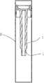
图6为安装图5中的通气构件后的雾化器的结构构示意图;Fig. 6 is a schematic diagram of the structure of the atomizer after the ventilation member in Fig. 5 is installed;
图7为通气构件的另一种优选方式与雾化套的连接结构示意图;Fig. 7 is a schematic diagram of another preferred mode of the ventilation member and the connection structure of the atomization sleeve;
图8为安装图7中所示出结构的雾化器;Fig. 8 is to install the atomizer of structure shown in Fig. 7;
图9为雾化器的现有结构示意图。Fig. 9 is a schematic diagram of the existing structure of the atomizer.
附图中各部分结构的标注说明:Notes on the structure of each part in the accompanying drawings:
1-通气管、2-气流通道、3-凸台、4-回流面、5-密封圈、7-加强筋、8-雾化套、9-吸嘴盖、10-密封套、11-支架、12-电热丝组件、13-空间、14-储油棉、31-导入壁、32-空腔、1’-通气管。1-Air pipe, 2-Airflow channel, 3-Boss, 4-Return surface, 5-Sealing ring, 7-Reinforcing rib, 8-Atomizing sleeve, 9-Nozzle cover, 10-Sealing sleeve, 11-Bracket , 12-heating wire assembly, 13-space, 14-oil storage cotton, 31-introduction wall, 32-cavity, 1'-ventilator.
具体实施方式Detailed ways
为了使本实用新型所要解决的技术问题、技术方案及有益效果更加清楚明白,以下结合实施例及附图,对本实用新型进行进一步详细说明。应当理解,此部分所描述的具体实施例仅可用以解释本实用新型,并不用于限定本实用新型。In order to make the technical problems, technical solutions and beneficial effects to be solved by the utility model clearer, the utility model will be further described in detail below in combination with the embodiments and accompanying drawings. It should be understood that the specific embodiments described in this section can only be used to explain the utility model, and are not intended to limit the utility model.
具体实施例一Specific embodiment one
如图1、图3所示,一种电子烟用通气构件,包括供气流通过的通气管1、设置在所述通气管1的一端的凸台3,所述凸台3中设有空腔32,所述空腔32与所述通气管1中的气流通道2相连通。所述空腔32的设置目的是,为了储存和净化从所述通气管1中出来的雾化烟油。所述空腔32可使冷凝在所述空腔32中的烟油回流至所述通气管1中。具体地,如图1所示,所述通气构件呈“T”型,所述凸台3与所述通气管1的连接面为一引导烟油回流至所述通气管1中斜面4(当然也可以设计为弧面或流线形的导流面)。As shown in Figures 1 and 3, a ventilation component for an electronic cigarette includes a
具体地,本实施例中所述凸台3与所述通气管1为一体成型结构。当然,本领域技术人员应知道,所述凸台3与所述通气管1设置为分体结构,然后通过粘接等固定方式连接在一起,也是可以的。Specifically, in this embodiment, the
具体地,本实施例中所述凸台3和所述通气管1为塑料材料制成(当然也可以由金属等其它材料制造)。其制造方式可以采用注塑的工艺,此工艺为惯用工艺,在此不作细述。Specifically, in this embodiment, the
具体实施例二Specific embodiment two
如图2所示,本实施例在包含具体实施例一中全部技术特征的基础上,其与实施例一的主要区别是:所述凸台3上沿所述通气管1的延伸端还延伸有导入壁31。As shown in Figure 2, on the basis of including all the technical features in the first embodiment, the main difference between this embodiment and the first embodiment is that the
如图4所示,本实施例中所述通气管1的外壁上还设置有加强筋7,所述加强筋7的长度小于所述通气管1。As shown in FIG. 4 , reinforcing
如图5所示,本实施例中所述凸台3的外表面还设置有密封圈5。As shown in FIG. 5 , a sealing
具体实施例三Specific embodiment three
如图6所示,一种电子烟用雾化器,包括雾化套8、吸嘴盖9、支架11、发热丝组件12,还包括固定设置在所述雾化套8中的通气构件,所述通气构件包括供气流通过的通气管1、设置在所述通气管1一端的凸台3,所述凸台3中设有空腔32,所述空腔32与所述通气管1中的气流通道2相连通;所述空腔32的设置目的是,为了储存和净化从所述通气管1中出来的雾化烟油。所述通气管1的另一端固定设置在所述支架11上,所述通气构件和所述支架11一起将所述雾化套8分隔出储烟油的空间13,该空间13内不设置储油棉。所述通气管1与所述支架11的连接处还设置有密封套10。As shown in FIG. 6 , an atomizer for electronic cigarettes includes an
进一步地,本实施例中所述空腔32可使冷凝在所述空腔32中的烟油回流至所述通气管1中。Further, in this embodiment, the
具体地,如图6所示,所述通气构件呈“T”型,所述凸台3与所述通气管1的连接面为一引导烟油回流至所述通气管1中斜面4(当然也可以设计为弧面或流线形的导流面)。Specifically, as shown in FIG. 6 , the ventilation member is in the shape of a "T", and the connection surface between the
具体地,本实施例中所述凸台3与所述通气管1为一体成型结构。当然,本领域技术人员应知道,所述凸台3与所述通气管1设置为分体结构,然后通过粘接等固定方式连接在一起,也是可以的。Specifically, in this embodiment, the
具体地,本实施例中所述凸台3和所述通气管1为塑料材料制成(当然也可以由金属等其它材料制造)。其制造方式可以采用注塑的工艺,此工艺为惯用工艺,在此不作细述。Specifically, in this embodiment, the
再如图6所示,本实施例中所述通气构件固定设置在所述雾化套8中,是通过所述凸台3与所述雾化套8的紧固配合来实现的。具体地,所述凸台3上沿所述通气管1的延伸端还延伸有导入壁31,所述凸台3的外表面还设置有密封圈5。在此优选实施例中,当所述凸台3和所述通气管1都为塑料制成的情况下(即塑料在注塑成形后的形变较大,不容易保证所述凸台3与所述雾化套8之间的精密配合。),制造厂商在生产时为降低漏烟油的风险,所述密封圈5的设置显得更为重要。As shown in FIG. 6 , in this embodiment, the venting member is fixedly arranged in the
具体实施例四Specific embodiment four
如图7、图8所示,本实施例在包含具体实施例三中全部技术特征的基础上,其与实施例一的主要区别是:本实施例中所述通气管1的外壁上还设置有加强筋7,所述加强筋7的长度小于所述通气管1。设置的所述加强筋7的长度小于所述通气管1的目的是,方便所述通气管1与所述支架8之间的固定装配。具体地,再如图8所示,所述通气管1的底部插入所述密封套10中,所述加强筋7处于在所述密封套10的上端。As shown in Figures 7 and 8, on the basis of including all the technical features in the third embodiment, the main difference between this embodiment and the first embodiment is that: the outer wall of the
具体实施例五Specific embodiment five
一种电子烟,包括电池组件和雾化器,该雾化器可以是实施例三、四中任一实施例中所描述的雾化器。An electronic cigarette includes a battery assembly and an atomizer, and the atomizer may be the atomizer described in any one of the third and fourth embodiments.
上述实施例仅是本实用新型的优选实施方式,应当指出对于本领域的普通技术人员来说,在不脱离本实用新型构思的前提下,还可以作若干个变形和改进,这些变形和改进也应视为本实用新型的保护范围之内。The above-mentioned embodiment is only the preferred embodiment of the present utility model, and it should be pointed out that for those of ordinary skill in the art, several modifications and improvements can be made without departing from the concept of the present utility model. Should be regarded as within the protection scope of the present utility model.
Claims (10)
Translated fromChinesePriority Applications (3)
| Application Number | Priority Date | Filing Date | Title |
|---|---|---|---|
| CN2012207002339UCN203015837U (en) | 2012-12-17 | 2012-12-17 | Mistorizer and aeration component for electronic cigarette and electronic cigarette |
| EP13197392.7AEP2742814B1 (en) | 2012-12-17 | 2013-12-16 | Atomizing device, ventilation member and electronic cigarette having same |
| US14/109,412US20140166030A1 (en) | 2012-12-17 | 2013-12-17 | Atomizing device, ventilation member and electronic cigarette having same |
Applications Claiming Priority (1)
| Application Number | Priority Date | Filing Date | Title |
|---|---|---|---|
| CN2012207002339UCN203015837U (en) | 2012-12-17 | 2012-12-17 | Mistorizer and aeration component for electronic cigarette and electronic cigarette |
Publications (1)
| Publication Number | Publication Date |
|---|---|
| CN203015837Utrue CN203015837U (en) | 2013-06-26 |
Family
ID=48639864
Family Applications (1)
| Application Number | Title | Priority Date | Filing Date |
|---|---|---|---|
| CN2012207002339UExpired - LifetimeCN203015837U (en) | 2012-12-17 | 2012-12-17 | Mistorizer and aeration component for electronic cigarette and electronic cigarette |
Country Status (3)
| Country | Link |
|---|---|
| US (1) | US20140166030A1 (en) |
| EP (1) | EP2742814B1 (en) |
| CN (1) | CN203015837U (en) |
Cited By (20)
| Publication number | Priority date | Publication date | Assignee | Title |
|---|---|---|---|---|
| CN103380952A (en)* | 2013-07-08 | 2013-11-06 | 深圳市合元科技有限公司 | Non-cotton atomizer and electronic cigarette |
| WO2015024269A1 (en)* | 2013-08-23 | 2015-02-26 | 吉瑞高新科技股份有限公司 | Atomization assembly and electronic cigarette |
| WO2015120639A1 (en)* | 2014-02-12 | 2015-08-20 | 吉瑞高新科技股份有限公司 | Electronic cigarette |
| CN103462224B (en)* | 2013-08-31 | 2015-10-14 | 卓尔悦(常州)电子科技有限公司 | Electronic smoke atomizer |
| WO2015168853A1 (en)* | 2014-05-06 | 2015-11-12 | 吉瑞高新科技股份有限公司 | Electronic cigarette capable of avoiding inhalation of condensed tobacco liquid into mouth |
| WO2016045084A1 (en)* | 2014-09-26 | 2016-03-31 | 惠州市吉瑞科技有限公司 | Atomizer sealing ring automatic assembling device and assembling method thereof |
| WO2016045076A1 (en)* | 2014-09-26 | 2016-03-31 | 深圳麦克韦尔股份有限公司 | Inhaler, atomizing assembly and atomizing core |
| WO2016065599A1 (en)* | 2014-10-31 | 2016-05-06 | 惠州市吉瑞科技有限公司 | Atomizing component and electronic cigarette |
| CN105578912A (en)* | 2013-07-24 | 2016-05-11 | Sis资源有限公司 | Cartomizer structure for automated assembly |
| WO2016115701A1 (en)* | 2015-01-22 | 2016-07-28 | 惠州市吉瑞科技有限公司 | Vaporization assembly and electronic cigarette |
| WO2016123781A1 (en)* | 2015-02-05 | 2016-08-11 | 惠州市吉瑞科技有限公司 | Atomisation assembly and electronic cigarette |
| WO2016141593A1 (en)* | 2015-03-12 | 2016-09-15 | 惠州市吉瑞科技有限公司 | Atomization assembly and electronic cigarette |
| CN106136327A (en)* | 2016-07-29 | 2016-11-23 | 深圳麦克韦尔股份有限公司 | Electronic cigarette and its atomizer |
| CN106572702A (en)* | 2014-09-03 | 2017-04-19 | 德国瀚辉包装机械责任有限公司 | electronic cigarette |
| CN109452691A (en)* | 2018-11-29 | 2019-03-12 | 深圳麦克韦尔股份有限公司 | Atomising device and electronic atomized equipment |
| CN110584205A (en)* | 2019-08-27 | 2019-12-20 | 深圳市云创高科电子有限公司 | Electronic cigarette |
| WO2020007242A1 (en)* | 2018-07-03 | 2020-01-09 | 常州市派腾电子技术服务有限公司 | Atomizer and electronic cigarette |
| US11083223B2 (en) | 2016-07-29 | 2021-08-10 | Shenzhen Smoore Technology Limited | Electronic cigarette and atomizer thereof |
| WO2022199546A1 (en)* | 2021-03-23 | 2022-09-29 | 深圳麦克韦尔科技有限公司 | Atomizer and electronic atomization device |
| US12042601B2 (en) | 2018-09-05 | 2024-07-23 | Shenzhen Smoore Technology Limited | Electronic atomization device and atomization assembly |
Families Citing this family (37)
| Publication number | Priority date | Publication date | Assignee | Title |
|---|---|---|---|---|
| US20160345631A1 (en) | 2005-07-19 | 2016-12-01 | James Monsees | Portable devices for generating an inhalable vapor |
| US9095175B2 (en) | 2010-05-15 | 2015-08-04 | R. J. Reynolds Tobacco Company | Data logging personal vaporizing inhaler |
| US9861772B2 (en) | 2010-05-15 | 2018-01-09 | Rai Strategic Holdings, Inc. | Personal vaporizing inhaler cartridge |
| US11344683B2 (en) | 2010-05-15 | 2022-05-31 | Rai Strategic Holdings, Inc. | Vaporizer related systems, methods, and apparatus |
| US8757147B2 (en) | 2010-05-15 | 2014-06-24 | Minusa Holdings Llc | Personal vaporizing inhaler with internal light source |
| US9259035B2 (en) | 2010-05-15 | 2016-02-16 | R. J. Reynolds Tobacco Company | Solderless personal vaporizing inhaler |
| US9999250B2 (en) | 2010-05-15 | 2018-06-19 | Rai Strategic Holdings, Inc. | Vaporizer related systems, methods, and apparatus |
| US10136672B2 (en) | 2010-05-15 | 2018-11-27 | Rai Strategic Holdings, Inc. | Solderless directly written heating elements |
| US10159278B2 (en) | 2010-05-15 | 2018-12-25 | Rai Strategic Holdings, Inc. | Assembly directed airflow |
| US9743691B2 (en) | 2010-05-15 | 2017-08-29 | Rai Strategic Holdings, Inc. | Vaporizer configuration, control, and reporting |
| US10279934B2 (en) | 2013-03-15 | 2019-05-07 | Juul Labs, Inc. | Fillable vaporizer cartridge and method of filling |
| US10039321B2 (en) | 2013-11-12 | 2018-08-07 | Vmr Products Llc | Vaporizer |
| US10159282B2 (en) | 2013-12-23 | 2018-12-25 | Juul Labs, Inc. | Cartridge for use with a vaporizer device |
| US10076139B2 (en) | 2013-12-23 | 2018-09-18 | Juul Labs, Inc. | Vaporizer apparatus |
| USD825102S1 (en) | 2016-07-28 | 2018-08-07 | Juul Labs, Inc. | Vaporizer device with cartridge |
| DE202014011260U1 (en) | 2013-12-23 | 2018-11-13 | Juul Labs Uk Holdco Limited | Systems for an evaporation device |
| US20160366947A1 (en) | 2013-12-23 | 2016-12-22 | James Monsees | Vaporizer apparatus |
| US10058129B2 (en) | 2013-12-23 | 2018-08-28 | Juul Labs, Inc. | Vaporization device systems and methods |
| USD842536S1 (en) | 2016-07-28 | 2019-03-05 | Juul Labs, Inc. | Vaporizer cartridge |
| MX394125B (en) | 2014-12-05 | 2025-03-24 | Juul Labs Inc | CALIBRATED DOSE CONTROL |
| GB201423318D0 (en) | 2014-12-29 | 2015-02-11 | British American Tobacco Co | Cartridge for use with apparatus for heating smokable material |
| GB201423316D0 (en) | 2014-12-29 | 2015-02-11 | British American Tobacco Co | Cartridge for use with apparatus for heating smokable material |
| GB201423315D0 (en) | 2014-12-29 | 2015-02-11 | British American Tobacco Co | Apparatus for heating smokable material |
| GB201423317D0 (en) | 2014-12-29 | 2015-02-11 | British American Tobacco Co | Apparatus for heating smokable material |
| CN104799439A (en)* | 2015-04-30 | 2015-07-29 | 深圳市美洛华科技有限公司 | Electronic cigarette |
| CO2018009342A2 (en) | 2016-02-11 | 2018-09-20 | Juul Labs Inc | Secure fixing cartridges for vaporizing devices |
| EP3413960B1 (en) | 2016-02-11 | 2021-03-31 | Juul Labs, Inc. | Fillable vaporizer cartridge and method of filling |
| US10405582B2 (en) | 2016-03-10 | 2019-09-10 | Pax Labs, Inc. | Vaporization device with lip sensing |
| USD849996S1 (en) | 2016-06-16 | 2019-05-28 | Pax Labs, Inc. | Vaporizer cartridge |
| USD836541S1 (en) | 2016-06-23 | 2018-12-25 | Pax Labs, Inc. | Charging device |
| USD851830S1 (en) | 2016-06-23 | 2019-06-18 | Pax Labs, Inc. | Combined vaporizer tamp and pick tool |
| USD848057S1 (en) | 2016-06-23 | 2019-05-07 | Pax Labs, Inc. | Lid for a vaporizer |
| USD887632S1 (en) | 2017-09-14 | 2020-06-16 | Pax Labs, Inc. | Vaporizer cartridge |
| USD865278S1 (en)* | 2018-02-05 | 2019-10-29 | Shenzhen Transpring Enterprise Ltd. | Vape part |
| US12225943B2 (en)* | 2019-06-26 | 2025-02-18 | Shenzhen Smoore Technology Limited | Atomizer and electronic atomization device |
| CN114097483B (en)* | 2021-11-09 | 2023-10-31 | 湖南大匠农业科技有限公司 | Humidification ventilation unit is used to ecological science and technology agricultural |
| CN120076725A (en)* | 2022-10-18 | 2025-05-30 | 日本烟草产业株式会社 | Cartridge, aerosol-generating device and non-combustion aspirator |
Family Cites Families (9)
| Publication number | Priority date | Publication date | Assignee | Title |
|---|---|---|---|---|
| CN101606758B (en)* | 2009-07-14 | 2011-04-13 | 方晓林 | Electronic cigarette |
| CN201830900U (en)* | 2010-06-09 | 2011-05-18 | 李永海 | Tobacco juice atomization device for electronic cigarette |
| EP2460424A1 (en)* | 2010-12-03 | 2012-06-06 | Philip Morris Products S.A. | An aerosol generating system with leakage prevention |
| CN202005248U (en)* | 2011-01-21 | 2011-10-12 | 万利龙 | Electronic atomization device capable substituting cigarette |
| CN102106611B (en)* | 2011-03-28 | 2013-01-16 | 深圳市康泰尔电子有限公司 | Electronic cigarette |
| US8528569B1 (en)* | 2011-06-28 | 2013-09-10 | Kyle D. Newton | Electronic cigarette with liquid reservoir |
| WO2013097158A1 (en)* | 2011-12-29 | 2013-07-04 | Liu Qiuming | Electronic cigarette with solid tobacco tar |
| US9854839B2 (en)* | 2012-01-31 | 2018-01-02 | Altria Client Services Llc | Electronic vaping device and method |
| CN202525085U (en)* | 2012-03-02 | 2012-11-14 | 深圳市合元科技有限公司 | Atomizer for electronic cigarette |
- 2012
- 2012-12-17CNCN2012207002339Upatent/CN203015837U/ennot_activeExpired - Lifetime
- 2013
- 2013-12-16EPEP13197392.7Apatent/EP2742814B1/enactiveActive
- 2013-12-17USUS14/109,412patent/US20140166030A1/ennot_activeAbandoned
Cited By (28)
| Publication number | Priority date | Publication date | Assignee | Title |
|---|---|---|---|---|
| CN103380952B (en)* | 2013-07-08 | 2016-05-04 | 深圳市合元科技有限公司 | Without cotton atomizer and electronic cigarette |
| CN103380952A (en)* | 2013-07-08 | 2013-11-06 | 深圳市合元科技有限公司 | Non-cotton atomizer and electronic cigarette |
| US10653177B2 (en) | 2013-07-24 | 2020-05-19 | Nu Mark Innovations Ltd | Cartomizer structure for automated assembly |
| CN105578912B (en)* | 2013-07-24 | 2018-12-04 | Sis资源有限公司 | Smoke grenade atomizer structure for automation component |
| CN105578912A (en)* | 2013-07-24 | 2016-05-11 | Sis资源有限公司 | Cartomizer structure for automated assembly |
| EP3037008A4 (en)* | 2013-08-23 | 2017-04-12 | Kimree Hi-Tech Inc. | Atomization assembly and electronic cigarette |
| WO2015024269A1 (en)* | 2013-08-23 | 2015-02-26 | 吉瑞高新科技股份有限公司 | Atomization assembly and electronic cigarette |
| CN103462224B (en)* | 2013-08-31 | 2015-10-14 | 卓尔悦(常州)电子科技有限公司 | Electronic smoke atomizer |
| WO2015120639A1 (en)* | 2014-02-12 | 2015-08-20 | 吉瑞高新科技股份有限公司 | Electronic cigarette |
| US10004260B2 (en) | 2014-02-12 | 2018-06-26 | Huizhou Kimree Technology Co., Ltd. Shenzhen Branch | Electronic cigarette |
| WO2015168853A1 (en)* | 2014-05-06 | 2015-11-12 | 吉瑞高新科技股份有限公司 | Electronic cigarette capable of avoiding inhalation of condensed tobacco liquid into mouth |
| CN106572702A (en)* | 2014-09-03 | 2017-04-19 | 德国瀚辉包装机械责任有限公司 | electronic cigarette |
| WO2016045084A1 (en)* | 2014-09-26 | 2016-03-31 | 惠州市吉瑞科技有限公司 | Atomizer sealing ring automatic assembling device and assembling method thereof |
| WO2016045076A1 (en)* | 2014-09-26 | 2016-03-31 | 深圳麦克韦尔股份有限公司 | Inhaler, atomizing assembly and atomizing core |
| CN106686994B (en)* | 2014-09-26 | 2019-06-28 | 惠州市吉瑞科技有限公司 | Atomizer sealing circle automatic assembling apparatus and its assembly method |
| CN106686994A (en)* | 2014-09-26 | 2017-05-17 | 惠州市吉瑞科技有限公司 | Atomizer sealing ring automatic assembling device and assembling method thereof |
| WO2016065599A1 (en)* | 2014-10-31 | 2016-05-06 | 惠州市吉瑞科技有限公司 | Atomizing component and electronic cigarette |
| WO2016115701A1 (en)* | 2015-01-22 | 2016-07-28 | 惠州市吉瑞科技有限公司 | Vaporization assembly and electronic cigarette |
| WO2016123781A1 (en)* | 2015-02-05 | 2016-08-11 | 惠州市吉瑞科技有限公司 | Atomisation assembly and electronic cigarette |
| WO2016141593A1 (en)* | 2015-03-12 | 2016-09-15 | 惠州市吉瑞科技有限公司 | Atomization assembly and electronic cigarette |
| CN106136327A (en)* | 2016-07-29 | 2016-11-23 | 深圳麦克韦尔股份有限公司 | Electronic cigarette and its atomizer |
| US11083223B2 (en) | 2016-07-29 | 2021-08-10 | Shenzhen Smoore Technology Limited | Electronic cigarette and atomizer thereof |
| WO2020007242A1 (en)* | 2018-07-03 | 2020-01-09 | 常州市派腾电子技术服务有限公司 | Atomizer and electronic cigarette |
| US12042601B2 (en) | 2018-09-05 | 2024-07-23 | Shenzhen Smoore Technology Limited | Electronic atomization device and atomization assembly |
| CN109452691A (en)* | 2018-11-29 | 2019-03-12 | 深圳麦克韦尔股份有限公司 | Atomising device and electronic atomized equipment |
| CN109452691B (en)* | 2018-11-29 | 2024-04-23 | 深圳麦克韦尔科技有限公司 | Atomizing device and electronic atomizing equipment |
| CN110584205A (en)* | 2019-08-27 | 2019-12-20 | 深圳市云创高科电子有限公司 | Electronic cigarette |
| WO2022199546A1 (en)* | 2021-03-23 | 2022-09-29 | 深圳麦克韦尔科技有限公司 | Atomizer and electronic atomization device |
Also Published As
| Publication number | Publication date |
|---|---|
| EP2742814B1 (en) | 2018-08-15 |
| US20140166030A1 (en) | 2014-06-19 |
| EP2742814A1 (en) | 2014-06-18 |
Similar Documents
| Publication | Publication Date | Title |
|---|---|---|
| CN203015837U (en) | Mistorizer and aeration component for electronic cigarette and electronic cigarette | |
| CN106820269B (en) | Electronic cigarette atomizer | |
| CN106235419B (en) | Electronic cigarette atomizer with liquid storage transition cavity | |
| US10039326B2 (en) | Ceramic atomizing wick and cigarette cartridge | |
| CN203105624U (en) | Electronic cigarette atomizer | |
| CN205831079U (en) | Large-volume lung electrophilic aerosolization core and nebulizer | |
| CN204837999U (en) | Electron smog spinning disk atomiser admits air in upper end | |
| WO2015070532A1 (en) | Atomizer and electronic cigarette | |
| CN206043435U (en) | Nebulizer and the electronic cigarette including the nebulizer | |
| WO2012152053A1 (en) | Atomization nozzle of electronic atomization inhaler | |
| CN107296300A (en) | A kind of electronic cigarette and its atomizer | |
| CN203692551U (en) | Electronic cigarette | |
| CN204317496U (en) | Atomising device and use the electronic cigarette of this atomising device | |
| CN208837106U (en) | A kind of electronic cigarette | |
| CN204670379U (en) | Atomizer and electronic cigarette | |
| CN207040879U (en) | A kind of Nebulizer for electronic cigarette and electronic cigarette | |
| CN213695701U (en) | A kind of aerosol generating device and atomizer | |
| CN204426704U (en) | An environmentally friendly and energy-saving electronic smoke atomizer | |
| CN104720116A (en) | Electronic cigarette atomizer | |
| CN220712886U (en) | Atomization structure and aerosol forming device thereof | |
| CN220343686U (en) | An electronic cigarette atomizer and electronic cigarette that can improve the utilization rate of tobacco oil | |
| CN215013618U (en) | Electronic cigarette cartridge | |
| CN206603260U (en) | Novel atomizing core on an electronic cigarette atomizer and its atomizer | |
| CN206137195U (en) | Make things convenient for electron smog spinning disk atomiser of liquid feeding | |
| CN209677361U (en) | E-cigarette with balanced oil supply |
Legal Events
| Date | Code | Title | Description |
|---|---|---|---|
| C14 | Grant of patent or utility model | ||
| GR01 | Patent grant | ||
| CB03 | Change of inventor or designer information | Inventor after:Li Yonghai Inventor after:Xu Zhongli Inventor after:He Youlin Inventor before:Li Yonghai Inventor before:Xu Zhongli | |
| CB03 | Change of inventor or designer information | ||
| COR | Change of bibliographic data | Free format text:CORRECT: INVENTOR; FROM: LI YONGHAI XU ZHONGLI TO: LI YONGHAI XU ZHONGLI HE YOULIN | |
| CX01 | Expiry of patent term | Granted publication date:20130626 | |
| CX01 | Expiry of patent term |