CN202993600U - Heat collecting device heating fluid through combined use of smoke waste heat and solar energy - Google Patents
Heat collecting device heating fluid through combined use of smoke waste heat and solar energyDownload PDFInfo
- Publication number
- CN202993600U CN202993600UCN2012206610500UCN201220661050UCN202993600UCN 202993600 UCN202993600 UCN 202993600UCN 2012206610500 UCN2012206610500 UCN 2012206610500UCN 201220661050 UCN201220661050 UCN 201220661050UCN 202993600 UCN202993600 UCN 202993600U
- Authority
- CN
- China
- Prior art keywords
- tube
- heat
- metal outer
- metal
- outer tube
- Prior art date
- Legal status (The legal status is an assumption and is not a legal conclusion. Google has not performed a legal analysis and makes no representation as to the accuracy of the status listed.)
- Expired - Fee Related
Links
- 239000002918waste heatSubstances0.000titleabstractdescription18
- 239000012530fluidSubstances0.000titleabstractdescription14
- 238000010438heat treatmentMethods0.000titleabstractdescription11
- 239000000779smokeSubstances0.000title1
- 239000002184metalSubstances0.000claimsabstractdescription99
- 239000011521glassSubstances0.000claimsabstractdescription41
- 229910000833kovarInorganic materials0.000claimsabstractdescription17
- 229910045601alloyInorganic materials0.000claimsabstractdescription16
- 239000000956alloySubstances0.000claimsabstractdescription16
- 238000003466weldingMethods0.000claimsabstract2
- 239000011248coating agentSubstances0.000claimsdescription8
- 238000000576coating methodMethods0.000claimsdescription8
- 238000010521absorption reactionMethods0.000claimsdescription2
- 239000003517fumeSubstances0.000claims4
- UGFAIRIUMAVXCW-UHFFFAOYSA-NCarbon monoxideChemical compound[O+]#[C-]UGFAIRIUMAVXCW-UHFFFAOYSA-N0.000abstractdescription22
- 239000003546flue gasSubstances0.000abstractdescription22
- 230000005855radiationEffects0.000description6
- 241000282414Homo sapiensSpecies0.000description1
- 230000009286beneficial effectEffects0.000description1
- 238000004134energy conservationMethods0.000description1
- 239000002803fossil fuelSubstances0.000description1
- 238000000034methodMethods0.000description1
- 239000002699waste materialSubstances0.000description1
Images
Classifications
- Y—GENERAL TAGGING OF NEW TECHNOLOGICAL DEVELOPMENTS; GENERAL TAGGING OF CROSS-SECTIONAL TECHNOLOGIES SPANNING OVER SEVERAL SECTIONS OF THE IPC; TECHNICAL SUBJECTS COVERED BY FORMER USPC CROSS-REFERENCE ART COLLECTIONS [XRACs] AND DIGESTS
- Y02—TECHNOLOGIES OR APPLICATIONS FOR MITIGATION OR ADAPTATION AGAINST CLIMATE CHANGE
- Y02E—REDUCTION OF GREENHOUSE GAS [GHG] EMISSIONS, RELATED TO ENERGY GENERATION, TRANSMISSION OR DISTRIBUTION
- Y02E10/00—Energy generation through renewable energy sources
- Y02E10/40—Solar thermal energy, e.g. solar towers
- Y02E10/44—Heat exchange systems
Landscapes
- Photovoltaic Devices (AREA)
Abstract
Translated fromChinese
Description
Translated fromChinese技术领域technical field
本实用新型涉及一种联合利用烟气余热与太阳能对流体进行加热的集热装置,属于太阳能与热能利用技术领域。The utility model relates to a heat collecting device for heating fluid by combined utilization of flue gas waste heat and solar energy, which belongs to the technical field of solar energy and thermal energy utilization.
背景技术Background technique
太阳的辐射功率达3.8 x 10²³ kW,其中,约1.08x 10¹⁴ kW辐射到地球表面。据估算,太阳在一月之内辐射到地球上的能量,可抵地球上包括石化燃料、原子能等在内的所有不可再生能源总储量的10倍之多,太阳能是真正取之不尽、用之不竭的能源。我国属太阳能资源相当丰富的国家,国土面积的2/3地区年日照时数大于2200h,单位面积太阳能辐射总量高于5016MJ/m2。开发和利用资源丰富、分布范围极广的太阳能,在给人类提供清洁能源的同时,还能达到零污染及零排放的要求,能极大地加速和促进我国节能减排目标的实现。同时在冶金行业中,各种丰富的余热资源往往得不到充分的利用,从各种冶金炉排出的高温烟气往往带走炉子供热量的20~50%,大量的带有余热的烟气被直接排放到环境中去,造成了能量的浪费。The radiant power of the sun reaches 3.8 x 10²³ kW, of which about 1.08 x 10¹⁴ kW radiates to the surface of the earth. It is estimated that the energy radiated by the sun to the earth within one month can be as much as 10 times the total reserves of all non-renewable energy sources on the earth, including fossil fuels and atomic energy. Inexhaustible energy. my country is a country rich in solar energy resources. The annual sunshine hours of 2/3 of the country's land area are more than 2200h, and the total solar radiation per unit area is higher than 5016MJ/m2. The development and utilization of solar energy, which is rich in resources and widely distributed, can not only provide clean energy to human beings, but also meet the requirements of zero pollution and zero emissions, which can greatly accelerate and promote the realization of my country's energy conservation and emission reduction goals. At the same time, in the metallurgical industry, various abundant waste heat resources are often not fully utilized. The high-temperature flue gas discharged from various metallurgical furnaces often takes away 20-50% of the heat supplied by the furnace, and a large amount of flue gas with waste heat It is directly discharged into the environment, resulting in a waste of energy.
发明内容Contents of the invention
本实用新型的目的在于提供一种联合利用烟气余热与太阳能对流体进行加热的集热装置,以将太阳能与烟气余热的利用结合起来,同时解决了常规太阳能集热器启动慢,稳定性差、加热速度慢、传热性能差,寿命短等问题。The purpose of this utility model is to provide a heat collecting device that combines the use of waste heat of flue gas and solar energy to heat fluid, so as to combine the utilization of solar energy and waste heat of flue gas, and at the same time solve the problem of slow startup and poor stability of conventional solar heat collectors , slow heating speed, poor heat transfer performance, short life and other problems.
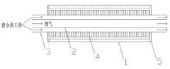
本实用新型的技术方案是:一种联合利用烟气余热与太阳能对流体进行加热的集热装置,包括真空玻璃管1、金属内管2、金属外管3和可伐合金5。金属内管2置于金属外管3内,金属内管2与金属外管3之间形成环形流道,金属外管3装在真空玻璃管1内,真空玻璃管顶端通过可伐合金5对金属外管3与真空玻璃管1进行密封焊接。The technical proposal of the utility model is: a heat collecting device for heating fluid by combined utilization of waste heat of flue gas and solar energy, comprising
所述金属外管3外壁装有翅片4。Fins 4 are installed on the outer wall of the metal
所述金属外管3外壁和翅片4上涂有选择性吸收涂层。The outer wall of the metal
所述金属内管2的内壁和外壁可轧制出螺纹状等增大对流传热系数的形状,金属外管3内壁可轧制出螺纹状等增大对流传热系数的形状。The inner wall and outer wall of the metal
采用金属内管2与金属外管3搭配的结构,金属内管2走余热烟气,烟气量可以根据太阳辐射强度以及用户需要的工质被加热温度来进行调节。金属内管2与金属外管3之间形成环形流道走被加热工质,被加热工质受到余热烟气与外部太阳能双重加热。金属内管2的内壁和外壁可轧制出螺纹状等增大对流传热系数的形状,金属外管3内壁同样可轧制出螺纹状等增大对流传热系数的形状。在金属外管3外壁焊接金属翅片,同时在金属翅片及金属外管3外壁面向阳光侧涂上选择性吸收涂层。使用有着与硬玻璃相近的线膨胀系数的可伐合金5对金属外管3和真空玻璃管1进行密封焊接,并将真空玻璃管1与金属外管3之间的空间抽成真空。The metal
本实用新型的工作原理是:太阳辐射透过真空玻璃管1,照射到金属内管2外壁和翅片4上,被选择性涂层吸收,温度上升,将热量传递给环形空间内的被加热工质。同时内管中通入带有一定温度的余热烟气,热量通过内管管壁传递给环形空间内的被加热工质,使被加热工质得到双重加热,能够更为迅速的增温。同时可以根据用户需要及太阳能辐照强度来调节余热烟气量,当正午太阳辐照强度很高时,可以减少烟气量,甚至完全使用太阳能来加热工质;而当夜晚没有太阳的时候则需要增大烟气量。The working principle of the utility model is: the solar radiation passes through the
本实用新型结合了太阳能集热器与烟气余热利用装置的优点,使本集热器同时利用太阳能以及烟气余热,使其既具有常规太阳能集热器无法具有的稳定性,又具有真空管集热器的传热性能好、使用可靠和热损失小等特点。真空管减少了集热装置的热损失。选择性涂层涂在金属外管外壁及翅片上,可充分吸收太阳能,同时降低真空管玻璃的运行温度。金属内管的内壁和外壁轧制出螺纹状等形状,金属外管内壁同样可轧制出螺纹状增大了对流传热系数。使用有着与硬玻璃相近的线膨胀系数的可伐合金对金属内管和真空玻璃管进行密封焊接,并将金属外管与真空玻璃管之间的空间抽成真空,避免玻璃管与金属外管间的热膨胀差导致的应力,有效的减小了集热器的热损系数,减少了热量的对外散失。而环形空间的设置使得被加热工质能更为迅速的被加热。本实用新型由于采用上述结构设计,使其既具有常规太阳能集热器无法具有的稳定性,又具有真空管集热器的传热性能好、使用可靠和热损失小等特点。The utility model combines the advantages of the solar heat collector and the flue gas waste heat utilization device, so that the heat collector can use solar energy and flue gas waste heat at the same time, so that it not only has the stability that conventional solar heat collectors cannot have, but also has the advantages of vacuum tube collectors. The heater has the characteristics of good heat transfer performance, reliable use and small heat loss. Evacuated tubes reduce heat loss from the collector. The selective coating is applied on the outer wall of the metal outer tube and the fins, which can fully absorb solar energy while reducing the operating temperature of the vacuum tube glass. The inner wall and the outer wall of the metal inner tube are rolled into shapes such as thread, and the inner wall of the metal outer tube can also be rolled into a thread to increase the convective heat transfer coefficient. Use Kovar alloy with a linear expansion coefficient similar to that of hard glass to seal and weld the metal inner tube and the vacuum glass tube, and evacuate the space between the metal outer tube and the vacuum glass tube to avoid the glass tube and the metal outer tube The stress caused by the thermal expansion difference between them effectively reduces the heat loss coefficient of the collector and reduces the heat loss to the outside. The arrangement of the annular space enables the heated working fluid to be heated more rapidly. Due to the adoption of the above structural design, the utility model not only has the stability that conventional solar heat collectors cannot have, but also has the characteristics of good heat transfer performance, reliable use and small heat loss of vacuum tube heat collectors.
本实用新型的有益效果是:The beneficial effects of the utility model are:
(1)采用金属内管与金属外管搭配的环形空间设置,使得在环形空间中流动的被加热工质能更有效的被加热,提高了升温速率;(1) The annular space setting with the metal inner tube and the metal outer tube is adopted, so that the heated working fluid flowing in the annular space can be heated more effectively, and the heating rate is improved;
(2)金属内管内壁及外壁,金属外管的内壁轧制出螺纹状等形状,有效增大了对流传热系数,进而增加了传热效率;(2) The inner wall and outer wall of the metal inner tube, and the inner wall of the metal outer tube are rolled into a threaded shape, which effectively increases the convective heat transfer coefficient, thereby increasing the heat transfer efficiency;
(3)真空玻璃管和金属外管之间抽成真空有效减小了热损系数,减少了热量的散失;(3) The vacuum between the vacuum glass tube and the metal outer tube effectively reduces the heat loss coefficient and heat loss;
(4)避免了真空玻璃管与金属外管间的热膨胀差导致的应力;(4) The stress caused by the thermal expansion difference between the vacuum glass tube and the metal outer tube is avoided;
(5)选择性吸收涂层涂在套管和翅片上,使得装置对太阳能辐射热量的吸收效果更好,同时可以使真空管玻璃的运行温度下降,在减少热损的同时,也延长了真空管的使用寿命;(5) The selective absorption coating is applied on the casing and fins, so that the device can better absorb the heat of solar radiation, and at the same time, it can reduce the operating temperature of the vacuum tube glass, while reducing heat loss, it also prolongs the life of the vacuum tube. service life;
附图说明Description of drawings
图1为本实用新型的结构示意图;Fig. 1 is the structural representation of the utility model;
图2为本实用新型的剖视示意图;Fig. 2 is the schematic sectional view of the utility model;
图中各标号为:1:真空玻璃管,2:金属内管,3:金属外管,4:翅片,5:可伐合金。Each label in the figure is: 1: vacuum glass tube, 2: metal inner tube, 3: metal outer tube, 4: fin, 5: Kovar alloy.
具体实施方式Detailed ways
下面结合附图和实施例,对本实用新型作进一步说明,但本实用新型的内容并不限于所述范围。Below in conjunction with accompanying drawing and embodiment, the utility model will be further described, but the content of the utility model is not limited to said range.
实施例1:如图1-2所示,一种联合利用烟气余热与太阳能对流体进行加热的集热装置,其特征在于:包括真空玻璃管1、金属内管2、金属外管3和可伐合金5;金属内管2置于金属外管3内,金属内管2与金属外管3之间形成环形流道,金属外管3装在真空玻璃管1内,真空玻璃管顶端通过可伐合金5对金属外管3与真空玻璃管1进行密封焊接。金属外管3外壁装有翅片4。金属外管3外壁和翅片4上涂有选择性吸收涂层。金属内管2的内壁和外壁可轧制出螺纹状,金属外管3内壁可轧制出螺纹状。Embodiment 1: As shown in Figure 1-2, a heat collecting device for heating fluid by combined use of flue gas waste heat and solar energy is characterized in that it includes a
实施例2:如图1-2所示,一种联合利用烟气余热与太阳能对流体进行加热的集热装置,其特征在于:包括真空玻璃管1、金属内管2、金属外管3和可伐合金5;金属内管2置于金属外管3内,金属内管2与金属外管3之间形成环形流道,金属外管3装在真空玻璃管1内,真空玻璃管顶端通过可伐合金5对金属外管3与真空玻璃管1进行密封焊接。金属外管3外壁装有翅片4。金属外管3外壁和翅片4上涂有选择性吸收涂层。Embodiment 2: As shown in Figure 1-2, a heat collecting device for heating fluid by combined use of flue gas waste heat and solar energy is characterized in that it includes a
实施例3:如图1-2所示,一种联合利用烟气余热与太阳能对流体进行加热的集热装置,其特征在于:包括真空玻璃管1、金属内管2、金属外管3和可伐合金5;金属内管2置于金属外管3内,金属内管2与金属外管3之间形成环形流道,金属外管3装在真空玻璃管1内,真空玻璃管顶端通过可伐合金5对金属外管3与真空玻璃管1进行密封焊接。金属外管3外壁装有翅片4。Embodiment 3: As shown in Figure 1-2, a heat collecting device for heating fluid by combined utilization of flue gas waste heat and solar energy is characterized in that it includes a
实施例4:如图1-2所示,一种联合利用烟气余热与太阳能对流体进行加热的集热装置,其特征在于:包括真空玻璃管1、金属内管2、金属外管3和可伐合金5;金属内管2置于金属外管3内,金属内管2与金属外管3之间形成环形流道,金属外管3装在真空玻璃管1内,真空玻璃管顶端通过可伐合金5对金属外管3与真空玻璃管1进行密封焊接。Embodiment 4: As shown in Figure 1-2, a heat collecting device for heating fluid by combined use of flue gas waste heat and solar energy is characterized in that it includes a
Claims (4)
Priority Applications (1)
| Application Number | Priority Date | Filing Date | Title |
|---|---|---|---|
| CN2012206610500UCN202993600U (en) | 2012-12-05 | 2012-12-05 | Heat collecting device heating fluid through combined use of smoke waste heat and solar energy |
Applications Claiming Priority (1)
| Application Number | Priority Date | Filing Date | Title |
|---|---|---|---|
| CN2012206610500UCN202993600U (en) | 2012-12-05 | 2012-12-05 | Heat collecting device heating fluid through combined use of smoke waste heat and solar energy |
Publications (1)
| Publication Number | Publication Date |
|---|---|
| CN202993600Utrue CN202993600U (en) | 2013-06-12 |
Family
ID=48564775
Family Applications (1)
| Application Number | Title | Priority Date | Filing Date |
|---|---|---|---|
| CN2012206610500UExpired - Fee RelatedCN202993600U (en) | 2012-12-05 | 2012-12-05 | Heat collecting device heating fluid through combined use of smoke waste heat and solar energy |
Country Status (1)
| Country | Link |
|---|---|
| CN (1) | CN202993600U (en) |
Cited By (1)
| Publication number | Priority date | Publication date | Assignee | Title |
|---|---|---|---|---|
| CN105318569A (en)* | 2014-06-12 | 2016-02-10 | 阿尔斯通技术有限公司 | Improved solar receiver configuration |
- 2012
- 2012-12-05CNCN2012206610500Upatent/CN202993600U/ennot_activeExpired - Fee Related
Cited By (2)
| Publication number | Priority date | Publication date | Assignee | Title |
|---|---|---|---|---|
| CN105318569A (en)* | 2014-06-12 | 2016-02-10 | 阿尔斯通技术有限公司 | Improved solar receiver configuration |
| CN105318569B (en)* | 2014-06-12 | 2019-01-08 | 通用电器技术有限公司 | improved solar receiver structure |
Similar Documents
| Publication | Publication Date | Title |
|---|---|---|
| Kumar et al. | An up-to-date review on evacuated tube solar collectors | |
| CN201059795Y (en) | Medium and high temperature concentrating solar heat collection system | |
| CN105553408B (en) | A kind of absorber plate photovoltaic and photothermal solar integrated module compound directly with glass cover-plate | |
| CN101562414A (en) | Solar energy vacuum heat collecting plate thermo-electric generating and collecting device | |
| CN102589153A (en) | Solar heating device and solar steam generating system | |
| CN102607206B (en) | Solar photovoltaic photo-thermal composite heat pipe vacuum tube | |
| CN112728776A (en) | External particle heat absorber and solar power generation system | |
| CN103335415B (en) | A kind of phase-change thermal storage solar water heater strengthening heat absorption | |
| CN201166472Y (en) | Reflective plate focusing energy storage tubular solar collector | |
| CN104567024A (en) | Sensible heat storing type cavity light collecting and heat absorbing type solar heat collecting device and method | |
| CN200961960Y (en) | Groove type light-gathering heat pipe type solar boiler device | |
| CN202254392U (en) | Vacuum pipe solar thermal collector with thermal storage function | |
| CN202419972U (en) | Square-pipe-type solar heat collector | |
| CN202993600U (en) | Heat collecting device heating fluid through combined use of smoke waste heat and solar energy | |
| CN201522111U (en) | A Bionic Flat Solar Heat Collector | |
| CN105716299A (en) | Solar heat pump water heater | |
| CN110375442A (en) | A high temperature solar cavity heat pipe central receiver | |
| CN201463326U (en) | A combined solar gas-liquid heat collector | |
| CN106196646A (en) | A kind of novel glass hot pipe type vacuum heat collection pipe | |
| CN2886433Y (en) | Inner tube through type solar heat collector | |
| CN102872785A (en) | Straight-through solar heat collection high-temperature reactor | |
| CN204141864U (en) | Solar energy high-temperature heat collection equipment | |
| CN109028606B (en) | A variable flow path metal wire-rock thermal storage solar collector | |
| CN202836290U (en) | Thermotube used for solar thermal collector | |
| CN106482361A (en) | A kind of novel tower-type solar heat absorber heating surface module |
Legal Events
| Date | Code | Title | Description |
|---|---|---|---|
| C14 | Grant of patent or utility model | ||
| GR01 | Patent grant | ||
| CF01 | Termination of patent right due to non-payment of annual fee | Granted publication date:20130612 Termination date:20141205 | |
| EXPY | Termination of patent right or utility model |