CN202991777U - Three-eccentric combination bolt - Google Patents
Three-eccentric combination boltDownload PDFInfo
- Publication number
- CN202991777U CN202991777UCN 201220696908CN201220696908UCN202991777UCN 202991777 UCN202991777 UCN 202991777UCN 201220696908CN201220696908CN 201220696908CN 201220696908 UCN201220696908 UCN 201220696908UCN 202991777 UCN202991777 UCN 202991777U
- Authority
- CN
- China
- Prior art keywords
- eccentric
- bolt
- raised line
- groove
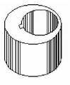
- pipe box
- Prior art date
- Legal status (The legal status is an assumption and is not a legal conclusion. Google has not performed a legal analysis and makes no representation as to the accuracy of the status listed.)
- Expired - Fee Related
Links
- 230000000295complement effectEffects0.000claimsdescription5
- 238000005034decorationMethods0.000description8
- 238000009434installationMethods0.000description6
- 238000010586diagramMethods0.000description4
- 238000012856packingMethods0.000description3
- 239000000725suspensionSubstances0.000description3
- 238000010276constructionMethods0.000description2
- 238000000034methodMethods0.000description2
- 229910052573porcelainInorganic materials0.000description2
- 239000004575stoneSubstances0.000description2
Images


Landscapes
- Supports Or Holders For Household Use (AREA)
Abstract
Description
Claims (2)
Priority Applications (1)
| Application Number | Priority Date | Filing Date | Title |
|---|---|---|---|
| CN 201220696908CN202991777U (en) | 2012-12-15 | 2012-12-15 | Three-eccentric combination bolt |
Applications Claiming Priority (1)
| Application Number | Priority Date | Filing Date | Title |
|---|---|---|---|
| CN 201220696908CN202991777U (en) | 2012-12-15 | 2012-12-15 | Three-eccentric combination bolt |
Publications (1)
| Publication Number | Publication Date |
|---|---|
| CN202991777Utrue CN202991777U (en) | 2013-06-12 |
Family
ID=48562961
Family Applications (1)
| Application Number | Title | Priority Date | Filing Date |
|---|---|---|---|
| CN 201220696908Expired - Fee RelatedCN202991777U (en) | 2012-12-15 | 2012-12-15 | Three-eccentric combination bolt |
Country Status (1)
| Country | Link |
|---|---|
| CN (1) | CN202991777U (en) |
Cited By (3)
| Publication number | Priority date | Publication date | Assignee | Title |
|---|---|---|---|---|
| CN102996589A (en)* | 2012-12-15 | 2013-03-27 | 周述文 | Three-eccentric combined bolt and construction process thereof |
| CN103615458A (en)* | 2013-11-21 | 2014-03-05 | 同济大学 | Eccentric-rotating-type unilateral bolt fastening member |
| CN104148875A (en)* | 2014-08-14 | 2014-11-19 | 广西鱼峰集团有限公司 | Deviation rectification device for reamed bolt holes and manufacturing method of deviation rectification device |
- 2012
- 2012-12-15CNCN 201220696908patent/CN202991777U/ennot_activeExpired - Fee Related
Cited By (4)
| Publication number | Priority date | Publication date | Assignee | Title |
|---|---|---|---|---|
| CN102996589A (en)* | 2012-12-15 | 2013-03-27 | 周述文 | Three-eccentric combined bolt and construction process thereof |
| CN102996589B (en)* | 2012-12-15 | 2015-06-03 | 周述文 | Three-eccentric combined bolt and construction process thereof |
| CN103615458A (en)* | 2013-11-21 | 2014-03-05 | 同济大学 | Eccentric-rotating-type unilateral bolt fastening member |
| CN104148875A (en)* | 2014-08-14 | 2014-11-19 | 广西鱼峰集团有限公司 | Deviation rectification device for reamed bolt holes and manufacturing method of deviation rectification device |
Similar Documents
| Publication | Publication Date | Title |
|---|---|---|
| CN202991777U (en) | Three-eccentric combination bolt | |
| CN102127957B (en) | Device and method for installing bolt and eccentric assembly in hole | |
| CN102996589A (en) | Three-eccentric combined bolt and construction process thereof | |
| CN203051383U (en) | Sealing bolt with mounting function | |
| CN202158046U (en) | Detachable expansion bolt | |
| CN203078439U (en) | Basic hand tool combined disc | |
| CN203284922U (en) | Hanging-buckle type pendant for curtain walls | |
| CN203909667U (en) | Improved tablet computer clamp | |
| CN203920508U (en) | A kind of automobile surface cover attaching parts | |
| CN2854055Y (en) | Improved beam unit polish rod grip | |
| CN201461711U (en) | Theftproof nut special fastening gasket provided with locking teeth at top surface | |
| CN202127154U (en) | Socket fixing structure | |
| CN203051375U (en) | Easy-assembly and disassembly bolt with mounting function | |
| CN103978917A (en) | Automobile trim connecting piece | |
| CN103204041A (en) | Top protection plate device of automobile shock absorber | |
| CN203267710U (en) | Top protection plate device of auto absorber | |
| CN202811922U (en) | Brake plate with installation plate | |
| CN201009899Y (en) | Special bow type top supporting device | |
| CN204185911U (en) | A kind of fastening devices for suspension member | |
| CN202118378U (en) | Fixing support for well way cable | |
| CN205401937U (en) | Large -scale container ship tuber pipe | |
| CN202152650U (en) | Novel hydraulic separation rope hanger | |
| CN201810624U (en) | Embedded installation structure | |
| CN105201977A (en) | Easily mounted mandril | |
| CN203051385U (en) | Multifunctional bolt |
Legal Events
| Date | Code | Title | Description |
|---|---|---|---|
| C14 | Grant of patent or utility model | ||
| GR01 | Patent grant | ||
| C41 | Transfer of patent application or patent right or utility model | ||
| TR01 | Transfer of patent right | Effective date of registration:20160805 Address after:350000, room 5, floor 68, block D, Hongshan science and Technology Park, No. 505, Hongshan Road, Gulou District, Fujian, Fuzhou Patentee after:Fujian Jin Nan Construction Development Co.,Ltd. Address before:Yangqiao Road Gulou District of Fuzhou city in Fujian province 350025 No. 231 Star City International box 1708 Patentee before:Zhou Shuwen | |
| CP01 | Change in the name or title of a patent holder | Address after:350025 Three Floors of Building 8-103, Yishan Cultural Creative Park, Gulou District, Fuzhou City, Fujian Province Patentee after:Jinnan Construction Group Co.,Ltd. Address before:350025 Three Floors of Building 8-103, Yishan Cultural Creative Park, Gulou District, Fuzhou City, Fujian Province Patentee before:Jinnan Construction Co.,Ltd. | |
| CP01 | Change in the name or title of a patent holder | ||
| CP03 | Change of name, title or address | Address after:350025 Three Floors of Building 8-103, Yishan Cultural Creative Park, Gulou District, Fuzhou City, Fujian Province Patentee after:Jinnan Construction Co.,Ltd. Address before:Room 505, 5th floor, Block D, Hongshan Science and Technology Park, 68 Hongshan Garden Road, Gulou District, Fuzhou City, Fujian Province Patentee before:Fujian Jin Nan Construction Development Co.,Ltd. | |
| CP03 | Change of name, title or address | ||
| CF01 | Termination of patent right due to non-payment of annual fee | Granted publication date:20130612 Termination date:20181215 | |
| CF01 | Termination of patent right due to non-payment of annual fee |