CN202982114U - Staple head component of circular tubular stapler - Google Patents
Staple head component of circular tubular staplerDownload PDFInfo
- Publication number
- CN202982114U CN202982114UCN 201220755812CN201220755812UCN202982114UCN 202982114 UCN202982114 UCN 202982114UCN 201220755812CN201220755812CN 201220755812CN 201220755812 UCN201220755812 UCN 201220755812UCN 202982114 UCN202982114 UCN 202982114U
- Authority
- CN
- China
- Prior art keywords
- nail
- housing
- opening
- tube
- circular
- Prior art date
- Legal status (The legal status is an assumption and is not a legal conclusion. Google has not performed a legal analysis and makes no representation as to the accuracy of the status listed.)
- Expired - Lifetime
Links
Images
Landscapes
- Surgical Instruments (AREA)
Abstract
Translated fromChinese
Description
Translated fromChinese技术领域technical field
本实用新型涉及一种圆管型吻合器,尤其是一种圆管型吻合器的钉头组件,属于医疗器械技术领域。The utility model relates to a circular tube stapler, in particular to a nail head assembly of the circular tube stapler, which belongs to the technical field of medical instruments.
背景技术Background technique
人们对痔的认识已有4000余年的历史,内痔治疗的传统方法,包括硬化剂注射、橡皮圈套扎以及各种形式的手术切除术等。这些方法均是针对痔本身进行治疗,旨在使痔核缩小或消失。在痔切除的外科手术中,有一种称为PPH手术方法,即在圆管型吻合器的帮助下进行的痔上粘膜环切术。People have known about hemorrhoids for more than 4,000 years. The traditional methods of internal hemorrhoid treatment include sclerosing agent injection, rubber band ligation and various forms of surgical resection. These methods all treat the hemorrhoid itself, aiming at shrinking or disappearing the hemorrhoid. Among the surgical operations for hemorrhoidectomy, there is a method called PPH operation, which is a circumcision of the suprahemorrhoid mucosa with the help of a circular stapler.
美国专利US6083241揭示了一种圆管型吻合器,其钉头组件包括钉砧和钉筒,钉筒内设钉仓、推钉片、钉,所述的钉砧和钉筒相对而置,手术中将痔上粘膜拉入到钉筒内,吻合时即将痔上粘膜环切。U.S. Patent No. 6,083,241 discloses a circular tubular stapler. Its nail head assembly includes an anvil and a nail barrel, and a nail bin, a nail pusher, and a nail are arranged in the nail barrel. The anvil and the nail barrel are opposite to each other. During the anastomosis, the suprahemorrhoidal mucosa is pulled into the nail barrel, and the suprahemorrhoidal mucosa is circumcised during anastomosis.
目前普遍使用的圆管型吻合器的钉筒,由于其自身结构的限制,使得其在手术的使用过程给医生提供的视窗有限,并且不利于组织的拉进和容纳更多的待切割组织,存在较大的局限性。Due to the limitation of its own structure, the nail barrel of the circular stapler commonly used at present makes it provide a limited viewing window for the doctor during the operation, and it is not conducive to pulling in the tissue and accommodating more tissue to be cut. There are major limitations.
实用新型内容Utility model content
本实用新型目的在于解决上述的技术问题,提供一种圆管型吻合器能实现大视窗大容量的钉头组件。The purpose of the utility model is to solve the above-mentioned technical problems, and provide a nail head assembly capable of realizing a large viewing window and a large capacity of a circular tubular stapler.
本实用新型的技术方案是:一种圆管型吻合器的钉头组件,至少包括钉筒和钉砧,所述钉筒包括壳体,所述壳体的近端用于与圆管型吻合器的本体连接,所述壳体内设有止涨管及推钉片;所述钉砧包括相互固定连接的钉砧环和钉砧轴,所述钉砧轴在所述止涨管内滑动,所述钉筒的壳体侧面开设有至少一个开口,所述开口与用于容纳待切组织的第一空腔贯通,所述止涨管的远端到壳体的近端的距离小于所述开口的最远边到壳体的近端的距离,至少有部分的第一空腔从所述开口中显露出来。The technical scheme of the utility model is: a nail head assembly of a circular tubular stapler, at least including a nail barrel and an anvil, the nail barrel includes a shell, and the proximal end of the shell is used for anastomosis with a circular tubular stapler. The body of the device is connected, and the housing is provided with an anti-expansion tube and a nail pusher; the anvil includes an anvil ring and an anvil shaft that are fixedly connected to each other, and the anvil shaft slides in the anti-expansion tube. The shell side of the nail barrel is provided with at least one opening, the opening communicates with the first cavity for accommodating the tissue to be cut, and the distance from the far end of the anti-expansion tube to the proximal end of the shell is smaller than the opening At least a portion of the first cavity is exposed from the opening.
优选的,所述钉筒的壳体中端开设有四个相对称的开口,相邻开口间均设有加强筋。Preferably, the middle end of the shell of the nail barrel is provided with four symmetrical openings, and reinforcing ribs are provided between adjacent openings.
优选的,在所述钉筒的壳体横截面中,所述开口的圆心角大于加强筋的圆心角。Preferably, in the shell cross section of the nail barrel, the central angle of the opening is larger than the central angle of the reinforcing rib.
优选的,所述推钉片的形状与所述钉筒相匹配,所述推钉片中端内部开设第二空腔,所述第二空腔对准所述钉筒的第一空腔。Preferably, the shape of the nail pusher matches the nail barrel, and a second cavity is opened inside the middle end of the nail pusher, and the second cavity is aligned with the first cavity of the nail barrel.
优选的,所述止涨管的近端延伸到壳体的近端,与所述止涨管配合的所述钉砧轴的近端也延伸至与止涨管的近端并相互配合。Preferably, the proximal end of the anti-expansion tube extends to the proximal end of the casing, and the proximal end of the anvil shaft matched with the anti-expansion tube also extends to the proximal end of the anti-expansion tube and cooperates with each other.
优选的,所述止涨管的通孔内设有至少一个导向槽,所述钉砧轴上相应地设置至少一个导向筋,所述导向筋可在所述导向槽内滑动。Preferably, at least one guide groove is provided in the through hole of the anti-expansion tube, and at least one guide rib is correspondingly provided on the anvil shaft, and the guide rib can slide in the guide groove.
本实用新型的优点是:The utility model has the advantages of:
1.通过在钉筒中端开设四个相对称的开口,在手术使用中可以提供大视窗,止涨管和加强筋的降低设置,以及推钉片的相应设置,使得手术中便于组织的拉进和容纳更多的切割组织;1. By opening four symmetrical openings in the middle of the nail barrel, a large viewing window can be provided during operation, the lowering setting of the anti-expansion tube and the reinforcing rib, and the corresponding setting of the pusher piece make it easy to pull in the tissue during the operation and accommodate more cutting tissue;
2.止涨管近端延伸设置,弥补了钉筒及加强筋降低设置带来的轴向和周向强度的不足;钉砧轴近端也延伸设置,增加了钉砧轴与止涨管的配合。2. The extension of the proximal end of the anti-expansion tube makes up for the lack of axial and circumferential strength caused by the lower setting of the nail barrel and reinforcing ribs; the proximal end of the anvil shaft is also extended to increase the distance between the anvil shaft and the anti-expansion tube. Cooperate.
附图说明Description of drawings
图1为本实用新型实施例一的结构示意图;Fig. 1 is the structural representation of the utility model embodiment one;
图2为本实用新型实施例一中钉筒的结构示意图;Fig. 2 is the structural representation of nail cylinder in the utility model embodiment one;
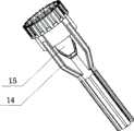
图3为本实用新型实施例一中推钉片的结构示意图。Fig. 3 is a schematic structural view of the nail pushing piece in Embodiment 1 of the present utility model.
其中:1、钉筒;2、钉砧环;21、钉砧轴;3、开口;31、最远边;4、加强筋;5、第一空腔;11、壳体;12、近端;13、止涨管;14、推钉片;15、第二空腔。Among them: 1. Nail barrel; 2. Nail anvil ring; 21. Nail anvil shaft; 3. Opening; 31. Farthest edge; 4. Reinforcing rib; 5. First cavity; 11. Shell; 12. Proximal end ; 13, stop pipe; 14, push nail piece; 15, the second cavity.
具体实施方式Detailed ways
实施例一:参见图1所示,本实用新型提供了一种圆管型吻合器的钉头组件,至少包括图2所示的钉筒1、图3所示的推钉片14以及钉砧。所述钉砧包括相互固定连接的钉砧环2和钉砧轴21。Embodiment 1: Referring to Fig. 1, the utility model provides a nail head assembly of a round tubular stapler, which at least includes the nail barrel 1 shown in Fig. 2, the
具体参见图2所示,所述钉筒1包括一个壳体11,所述壳体11的近端12用于与圆管型吻合器的本体连接,所述壳体11内设有止涨管13及推钉片14,止涨管13包括一个通孔,该通孔用于使得钉砧的钉砧轴21滑动通过,优选的实施方案为,止涨管13的通孔内设有两个导向槽,所述钉砧轴21上相应地设置两个导向筋,所述导向筋可在所述导向槽内滑动。Referring specifically to Fig. 2, the nail barrel 1 includes a housing 11, the proximal end 12 of the housing 11 is used to connect with the body of the circular tubular stapler, and the housing 11 is provided with an anti-expansion tube 13 and the
本优选实施例中,在所述钉筒1的侧面开设有四个相对称的开口3,这样的四面开口设置可以给医护人员在手术中提供大视窗,相邻开口3间均设有加强筋4。所述开口3与用于容纳待切组织的第一空腔5贯通,所述止涨管13的远端到壳体11的近端12的距离小于所述开口3的最远边31到壳体11的近端12的距离,至少有部分的第一空腔5从所述开口3中显露出来,使得手术中便于组织的拉进和容纳更多的切割组织。而且在所述钉筒1的壳体11横截面中,所述开口3的圆心角大于加强筋4的圆心角。这样的大开口设置,使医生在手术时具有极佳的观察视角。In this preferred embodiment, four symmetrical openings 3 are provided on the side of the nail barrel 1. Such openings on four sides can provide medical staff with a large viewing window during the operation, and reinforcing ribs are provided between the adjacent openings 3. 4. The opening 3 communicates with the first cavity 5 for accommodating the tissue to be cut, and the distance from the distal end of the anti-expansion tube 13 to the proximal end 12 of the casing 11 is smaller than the distance from the farthest edge 31 of the opening 3 to the casing. The distance from the proximal end 12 of the body 11, at least part of the first cavity 5 is exposed from the opening 3, so that it is convenient to pull in the tissue and accommodate more cut tissue during the operation. Moreover, in the cross section of the housing 11 of the nail barrel 1 , the central angle of the opening 3 is larger than the central angle of the reinforcing rib 4 . Such a large opening allows doctors to have an excellent viewing angle during surgery.
进一步地,所述加强筋4的一端与钉筒1的壳体11一体设置,另一端的长度等于所述止涨管13的长度。结合图3所示,所述推钉片14的形状与所述钉筒1相匹配,所述推钉片14中端内部开设第二空腔15,所述第二空腔15对准所述钉筒1的第一空腔5。推钉片14与钉筒1的设置类似,同样是为了带来更大的收容空间,容纳更多的待切组织。Further, one end of the reinforcing rib 4 is integrated with the housing 11 of the nail barrel 1 , and the length of the other end is equal to the length of the expansion stop pipe 13 . As shown in FIG. 3 , the shape of the
为了弥补止涨管13和加强筋4的降低带来的器械的轴向和周向强度的不足,止涨管近端进行了延伸设置,同时钉砧轴也相应的近端延伸,增加钉砧轴与止涨管的配合。具体为:所述止涨管的近端延伸到壳体的近端,与所述止涨管配合的所述钉砧轴的近端也延伸至与止涨管的近端。In order to make up for the lack of axial and circumferential strength of the instrument caused by the reduction of the anti-expansion tube 13 and the reinforcing rib 4, the proximal end of the anti-expansion tube is extended, and the anvil shaft is also extended correspondingly at the proximal end, increasing the anvil. Coordination of the shaft and the anti-expansion tube. Specifically, the proximal end of the anti-expansion tube extends to the proximal end of the casing, and the proximal end of the anvil shaft matched with the anti-expansion tube also extends to the proximal end of the anti-expansion tube.
本实用新型中的远端和近端是以医生手术时器械所处的位置而言,距离医生较近的一端为近端,距离医生较远的一端为远端。The far end and the near end in the utility model are based on the position of the instrument during the doctor's operation, the end closer to the doctor is the near end, and the end farther away from the doctor is the far end.
本实用新型尚有多种实施方式,凡采用等同替换或者等效变换而形成的所有技术方案,均落在本实用新型要求保护的范围之内。The utility model still has multiple implementation modes, and all technical solutions formed by equivalent replacement or equivalent transformation all fall within the protection scope of the utility model.
Claims (6)
Priority Applications (15)
| Application Number | Priority Date | Filing Date | Title |
|---|---|---|---|
| CN 201220755812CN202982114U (en) | 2012-12-29 | 2012-12-29 | Staple head component of circular tubular stapler |
| ES13866809.0TES2669734T3 (en) | 2012-12-29 | 2013-12-27 | Circular stapler and staple head assembly thereof |
| EP13866809.0AEP2939611B1 (en) | 2012-12-29 | 2013-12-27 | Circular stapler and staple head assembly thereof |
| PT138668090TPT2939611T (en) | 2012-12-29 | 2013-12-27 | Circular stapler and staple head assembly thereof |
| BR112015015572-3ABR112015015572B1 (en) | 2012-12-29 | 2013-12-27 | CIRCULAR CLAMP HEAD AND CIRCULAR STAPLER ASSEMBLY |
| CA2896382ACA2896382C (en) | 2012-12-29 | 2013-12-27 | Circular stapler and staple head assembly thereof |
| AU2013369764AAU2013369764B2 (en) | 2012-12-29 | 2013-12-27 | Circular stapler and staple head assembly thereof |
| PCT/CN2013/090676WO2014101830A1 (en) | 2012-12-29 | 2013-12-27 | Circular stapler and staple component thereof |
| PL13866809TPL2939611T3 (en) | 2012-12-29 | 2013-12-27 | Circular stapler and staple head assembly thereof |
| RU2015126341ARU2619381C2 (en) | 2012-12-29 | 2013-12-27 | Circular stapling device and head unit of such device |
| HUE13866809AHUE038264T2 (en) | 2012-12-29 | 2013-12-27 | Circular stapler and staple head assembly thereof |
| TR2018/06997TTR201806997T4 (en) | 2012-12-29 | 2013-12-27 | Circle shaped stapler / stapler and staple head assembly. |
| JP2015548181AJP6096927B2 (en) | 2012-12-29 | 2013-12-27 | Circular stapler and staple assembly thereof |
| US14/655,350US10433848B2 (en) | 2012-12-29 | 2013-12-27 | Circular stapler and staple head assembly thereof |
| US16/553,756US11096695B2 (en) | 2012-12-29 | 2019-08-28 | Circular stapler and staple head assembly thereof |
Applications Claiming Priority (1)
| Application Number | Priority Date | Filing Date | Title |
|---|---|---|---|
| CN 201220755812CN202982114U (en) | 2012-12-29 | 2012-12-29 | Staple head component of circular tubular stapler |
Publications (1)
| Publication Number | Publication Date |
|---|---|
| CN202982114Utrue CN202982114U (en) | 2013-06-12 |
Family
ID=48553348
Family Applications (1)
| Application Number | Title | Priority Date | Filing Date |
|---|---|---|---|
| CN 201220755812Expired - LifetimeCN202982114U (en) | 2012-12-29 | 2012-12-29 | Staple head component of circular tubular stapler |
Country Status (1)
| Country | Link |
|---|---|
| CN (1) | CN202982114U (en) |
Cited By (3)
| Publication number | Priority date | Publication date | Assignee | Title |
|---|---|---|---|---|
| CN103340660A (en)* | 2013-07-26 | 2013-10-09 | 苏州法兰克曼医疗器械有限公司 | PPH (procedure for prolapse and hemorrhoids) stapler |
| WO2014101830A1 (en)* | 2012-12-29 | 2014-07-03 | 苏州天臣国际医疗科技有限公司 | Circular stapler and staple component thereof |
| CN103908315A (en)* | 2012-12-29 | 2014-07-09 | 苏州天臣国际医疗科技有限公司 | Nail head component of circular tube anastomat |
- 2012
- 2012-12-29CNCN 201220755812patent/CN202982114U/ennot_activeExpired - Lifetime
Cited By (7)
| Publication number | Priority date | Publication date | Assignee | Title |
|---|---|---|---|---|
| WO2014101830A1 (en)* | 2012-12-29 | 2014-07-03 | 苏州天臣国际医疗科技有限公司 | Circular stapler and staple component thereof |
| CN103908315A (en)* | 2012-12-29 | 2014-07-09 | 苏州天臣国际医疗科技有限公司 | Nail head component of circular tube anastomat |
| CN103908315B (en)* | 2012-12-29 | 2016-07-13 | 苏州天臣国际医疗科技有限公司 | Nail head assembly of a circular tubular stapler |
| US10433848B2 (en) | 2012-12-29 | 2019-10-08 | Suzhou Touchstone International Medical Science Co., Ltd. | Circular stapler and staple head assembly thereof |
| US11096695B2 (en) | 2012-12-29 | 2021-08-24 | Touchstone International Medical Science Co., Ltd. | Circular stapler and staple head assembly thereof |
| CN103340660A (en)* | 2013-07-26 | 2013-10-09 | 苏州法兰克曼医疗器械有限公司 | PPH (procedure for prolapse and hemorrhoids) stapler |
| CN103340660B (en)* | 2013-07-26 | 2016-03-09 | 苏州法兰克曼医疗器械有限公司 | Mucosa circumcision stapler in hemorrhoid |
Similar Documents
| Publication | Publication Date | Title |
|---|---|---|
| CN202982106U (en) | Surgical operating instrument | |
| JP6096927B2 (en) | Circular stapler and staple assembly thereof | |
| CN103908313A (en) | Surgical operating instrument | |
| CN101455577A (en) | Medical cutting bookbinding device | |
| CN202982114U (en) | Staple head component of circular tubular stapler | |
| CN105796140B (en) | Hysteroscope surgical operation seaming and cutting device | |
| CN209220427U (en) | A kind of Gastrointestinal Endoscopes pincers road surgical instrument | |
| CN103908315B (en) | Nail head assembly of a circular tubular stapler | |
| CN103908732B (en) | The space expander of device for endoscopic thyroid surgery | |
| CN202982113U (en) | Staple head component of circular tubular stapler | |
| CN102028535B (en) | Multifunctional endoscopy suction device | |
| CN205795772U (en) | A kind of peritoneoscope liver lifts pincers | |
| CN201361347Y (en) | Novel anus dilator seat | |
| CN200939163Y (en) | Loop push trocar | |
| CN208677450U (en) | An efficient biopsy spatula for bronchoscopy | |
| CN219594700U (en) | Disposable linear cutting anastomat for endoscope | |
| CN107647888B (en) | Efficient biopsy shovel for bronchoscope | |
| CN203226893U (en) | Instrument for establishing laparoscopic channel | |
| CN204520824U (en) | A kind of Novel suture assembly and apply the stiching instrument of this suturing assembly | |
| CN204364046U (en) | A kind of chamber mirror surgical operation seaming and cutting device | |
| CN201135469Y (en) | Surgical instrument binding head | |
| CN206587013U (en) | A kind of endoscope casing tube formula circular cutter | |
| CN218186901U (en) | A Veress needle that lifts the abdominal wall and guides the peritoneotomy | |
| CN110448365A (en) | Subtract hole laparoscope puncture outfit with protective case | |
| CN221808012U (en) | Endoscopic cutting and suturing device with flexible embedded structure |
Legal Events
| Date | Code | Title | Description |
|---|---|---|---|
| C14 | Grant of patent or utility model | ||
| GR01 | Patent grant | ||
| AV01 | Patent right actively abandoned | Granted publication date:20130612 Effective date of abandoning:20160713 | |
| AV01 | Patent right actively abandoned | Granted publication date:20130612 Effective date of abandoning:20160713 | |
| C25 | Abandonment of patent right or utility model to avoid double patenting |